Drain Design
Drain paths can be created by:
Surveying them in the 'Collection' wizard step
Importing them
Using the Auto drains tool
Using the Pattern drains tool
Drain Design allows slope profile and cross section design choices before “burning” (embedding) drains into the map for implementation.
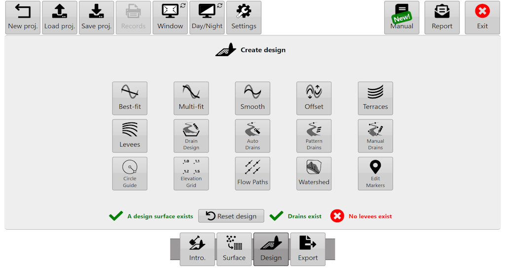
NOTE: If a surface & drain exist, the surface should be designed first & the drain second. If you need to edit drain elevation data you can return to the 'Collect' wizard step to edit the drain line. However you will lose current project designs.
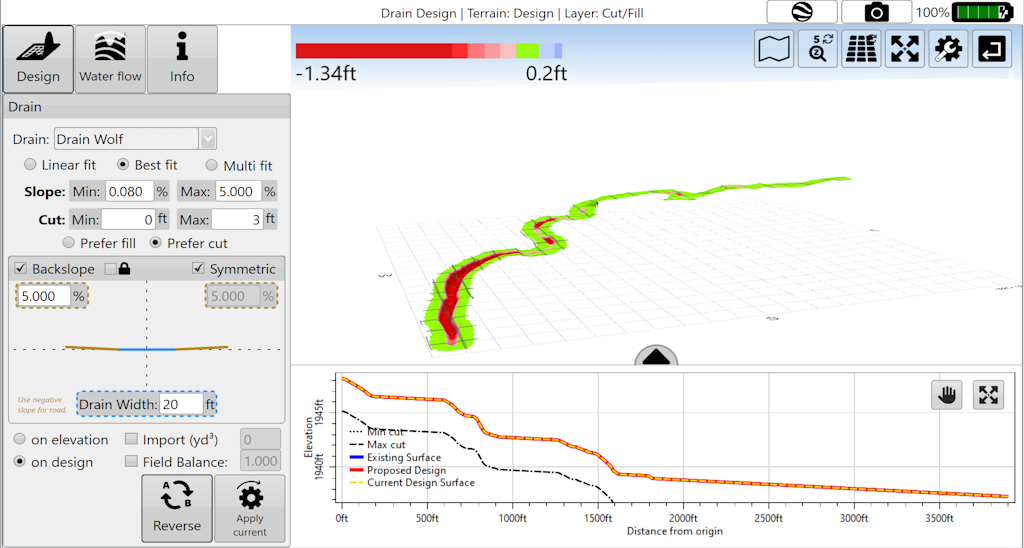
Select a drain and the depth/elevation profile of the drain will show in the plot at bottom right (this chart may need to be dragged up into view). Use the 'AB Reverse' button to make sure your drain is falling from left to right in the profile chart, this will make sure that slope values are all positive and make adjustments a lot easier.
Drain paths can be changed into roads by entering a negative backslope. This will cause the drain design to be inverted.
NOTE: The positioning/layout of drain paths is not considered part of 'Drain Design'. They can be adjusted in the surfacing step for driven drains or in auto drains/pattern drains.
When applying drain designs there are 3 different modes that adjust the path of the drain which are Linear fit, Best fit and Multi fit.
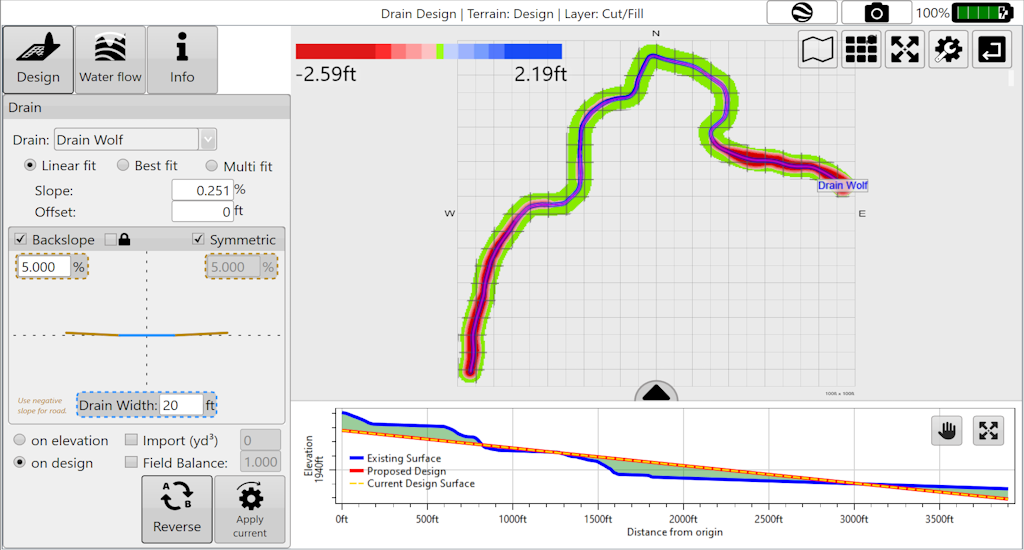
Linear fit
Creates a single straight plane along the drain path.
'Slope'- is the gradient at which the drain is installed to ensure that water flows in the direction you want.
'Offset'- allows for vertical offsetting of the drain. Setting a positive value will lift the offset creating a fill effect along the entire drain, while a negative value in the offset will lower the design height creating a deeper cut drain.
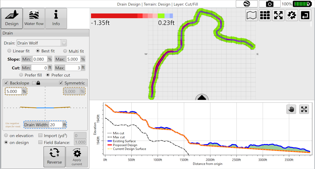
Best fit
Adjusts the slope to try and follow the natural curve of the field. Similar to multi-fit field design. Cutta Ditch
NOTE: Best-fit in drains is equivalent to Multi-fit in full field design. This incongruity comes from a desire to try and match the naming conventions of the John Deere SWP+ product (which is superseded by T3RRA Cutta and T3RRA Ditch).
‘Min. Slope’- The lowest gradient of slope you will accept in the drain.
‘Max. Slope’- The highest gradient slope you will accept in the drain
‘Min. Cut’- ensures the design will consistently cut at least this amount.
‘Max. Cut’ sets the maximum depth that the design will cut to and ensures that it never exceeds this point.
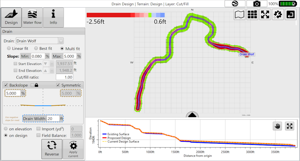
Multi fit
Applies both cut and fill, and can be used to remove points of erosion and build up that would cause issues. Best used when maintaining existing drains.
‘Min. Slope’- The minimum allowable gradient of the slope.
‘Max. Slope’- The maximum allowable gradient of the slope.
‘Start Elevation’- The desired elevation point at which the design will begin (at point A). Set to be greater than, equal to, or less than the set value adjusting the start elevation value of the design to be no higher or lower than the set value
‘End Elevation’- The desired elevation of the final point on the design also referred to as (point B). Set to be greater than, equal to, or less than the set value to ensure that the final elevation of the design is not higher or lower than the set value.
NOTE: Multi fit tries to balance the cuts and fills using the start and end elevations. If the design parameters won’t work you will see the message: “Model is too constrained” .
General settings
These settings are present in all drain design modes.
‘Cut/Fill ratio’ - please refer to definitions in appendix. The following settings and buttons are all constant between all three modes in Drain Design.
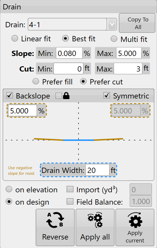
'Copy To All' - copy the settings of the currently selected drain to all other drains present in the project. If all drains are likely to require similar parameters this can be a big time saver.
'Backslope' (batter) is the gradient of the drain walls. A higher backslope value means a sharper drop into the drain. If no backslope is desired, leave the 'Backslope' box unchecked. If you wish to make a road, enter a negative backslope value.
"Symmetric' when checked, will mirror the batter design. When unchecked, the batter slope can be changed independently for both sides.
‘Lock Backslope’ is mainly intended to be used when working with drain lines - not full surfaces. Will cause the surface to be ignored and the backslopes will be created to their maximum extent. Note: that the drain bottom will always be burnt in, regardless of the surface elevation. I.e., if you offset a drain up 5m, you would always have a drain bottom burnt in, regardless of if lock backslope is on or off
'Drain Width' allows you to control how wide the bottom of the drain is. The drain bottom is always horizontal. If you want a drain bottom with a defined non-zero cross slope you should manually set the cross slope control on your implement in the ‘Implementation’ stage of operation.
'Cut/fill ratio' allows you to compensate for soil compaction characteristics.
'Apply All' allows you to apply all the drains in the field, not just the drain that is currently selected.
Choosing to apply ‘on elevation’ or ‘on design’ chooses the elevation profile that is used to calculate the designed surface. For example, one drain requires a different design than the others present, you will apply the design ‘on elevation’ to All then select the drain from the drop down and apply a different design ‘on design’ to that drain alone.
NOTE: choosing to design on a design will continue to lower the surface of the drain.
Press 'Apply All' (the image of 3 cogs) to apply all drains at once
Press 'Apply' (the image of 1 cog) to apply only the currently selected drain.
After editing your drains in the surveying step, return to create a new drain design in the 'Design' wizard step. If a surface and drain exist, the surface should be designed first and the drain second.
After designing the drain and applying it, it is “burned” (embedded) into the field surface model. At this point you can begin implementing in the same way you would a normal field design. If you are using a constant depth drain cutting implement you may not be interested in the depth profile. You may want to only rely on the paths for guidance and not elevation control. In this case there is no need to create the drain profile (unless you want to look at the effects of the drains in the rainfall simulation).
Option: Use the 'Export' button on the wizard screen to export the drain paths to an RCD folder structure (JD Guidance lines). You can export ditch track guidance lines that will steer your tractor on exactly the right path to accurately and efficiently remove your wet areas (John Deere AutoTrac™ required).
Here is a video on Drain Design Tools.