Slope Indicator
 The ‘Slope Indicator’ tool is used to measure the slope of a particular area. When the tool is selected the cursor will change into a cross. Once a point has been selected, slope indicators will appear on the field and a pop-up window will be opened. The slope indicators can be manipulated on the field by using the yellow anchor points.
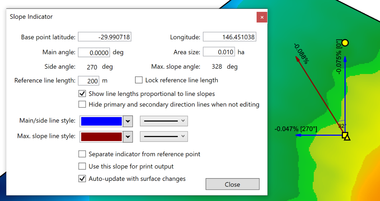
- ‘Base point latitude’ and ‘Longitude’. These options control the position of the indicator on the field. They can be manually changed by typing new values in the boxes. These changes take immediate effect.
- ‘Main angle’ This option controls the direction of the main direction line. The line changes size proportionally to the slope of the area. Until the settings have been finalized, the direction of the main line can be modified with the yellow circle anchor.
- ‘Area size’. This option controls the sample area of the slope indicator. The elevations within the sample area are read to determine the displayed slope. Increasing the value displayed in the box reads more elevations and provides a more averaged slope measurement. Decreasing the area size gives a more specific and local slope measurement.
- ‘Side angle’ and ‘Max. slope angle’ cannot be changed directly - they display the secondary heading and the heading of the maximum slope at the selected location.
- ‘Reference line length’ allows you to change the maximum length of the slope indicators.
- ‘Lock reference line length’. When selected, this locks the reference line to its current length while dragging the yellow circle.
- ‘Show line lengths proportional to line slopes’. When selected, the lines will adjust in length to match the slope of the selected area. They will not exceed the reference line length.
- ‘Hide primary and secondary direction lines when not editing’, selecting this option will hide the main direction line and the secondary direction line once all settings have been finalized and the window has been closed.
- ‘Main/side line style’ the left drop down menu lets you select the color of the two slope lines at 90° to each other. The right drop down menu lets you select their thickness.
- ‘Max. slope line style’ the left drop down menu allows you to change the color of the maximum slope line. The right drop down menu allows you to change the thickness of the slope line.
- ‘Separate indicator from reference point’. This option allows you to move the indicator to another location while still using the same reference point. Once settings have been finalized the reference point and area will be invisible.
- ‘Use this slope for print output’. This option selects this slope for printing output.
- ‘Auto-update with the surface changes’. This check box will cause the slope indicator to adjust the displayed values depending on the top most layer in the surface selection.