Drains and Banks Tool
 The drains and banks tool is great for planning drains, ditches, channels, and troughs. Also roads, banks, ridges, levees and embankments. It also lets you plan more complex structures, like roads with drains on each side, custom contours - even whole shed pads and feeding lots. The key attribute is that you can create these structures by extruding a cross section design along a line (or lines). If you can describe your cross section and the path it should follow, then you can design drains, roads, pads, borrow-pits and contours.
The tool requires three inputs - paths, longitudinal design, and cross sections. They can be edited independently while using this tool, although the line must exist to edit the longitudinal design.
Create the path
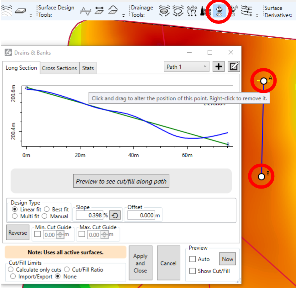
When you first open the tool, define the path by clicking on the surface at its starting point, any midpoints and finally the endpoint. The points can be dragged around to move them, and right-clicked to delete them.
Tip: Shift+click to add points to the beginning rather than the end.
 A single drain layer can contain multiple paths. To add more paths, use the buttons in the top right corner:
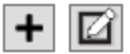
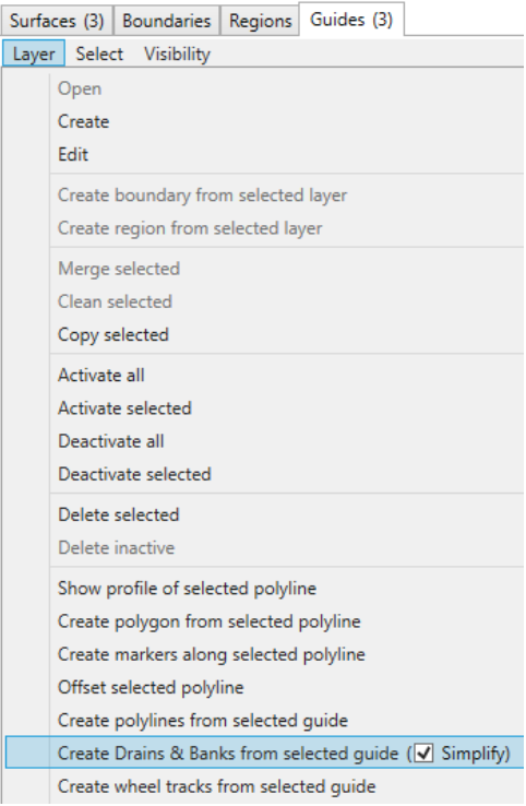
If you’ve already got your path in an existing guide, then you can create a drain from it. To do so, select the layer in guides and then in the Layers menu, click “Create Drains and Banks from selected guide”. The simplify option is recommended, as it removes any points that don’t contribute to the shape of the path. This makes designing easier and quicker to run.
Design your path’s elevations (long section)
With a path chosen and shown on the map, there are two more things to design - the longitudinal (aka long section) and the cross section. The longitudinal design defines how the elevations/depths vary as you travel from the path’s start to end.

Edit Cross Sections
The cross sections define the shape to extrude along the chosen path, following the elevations/depths from the long section design.
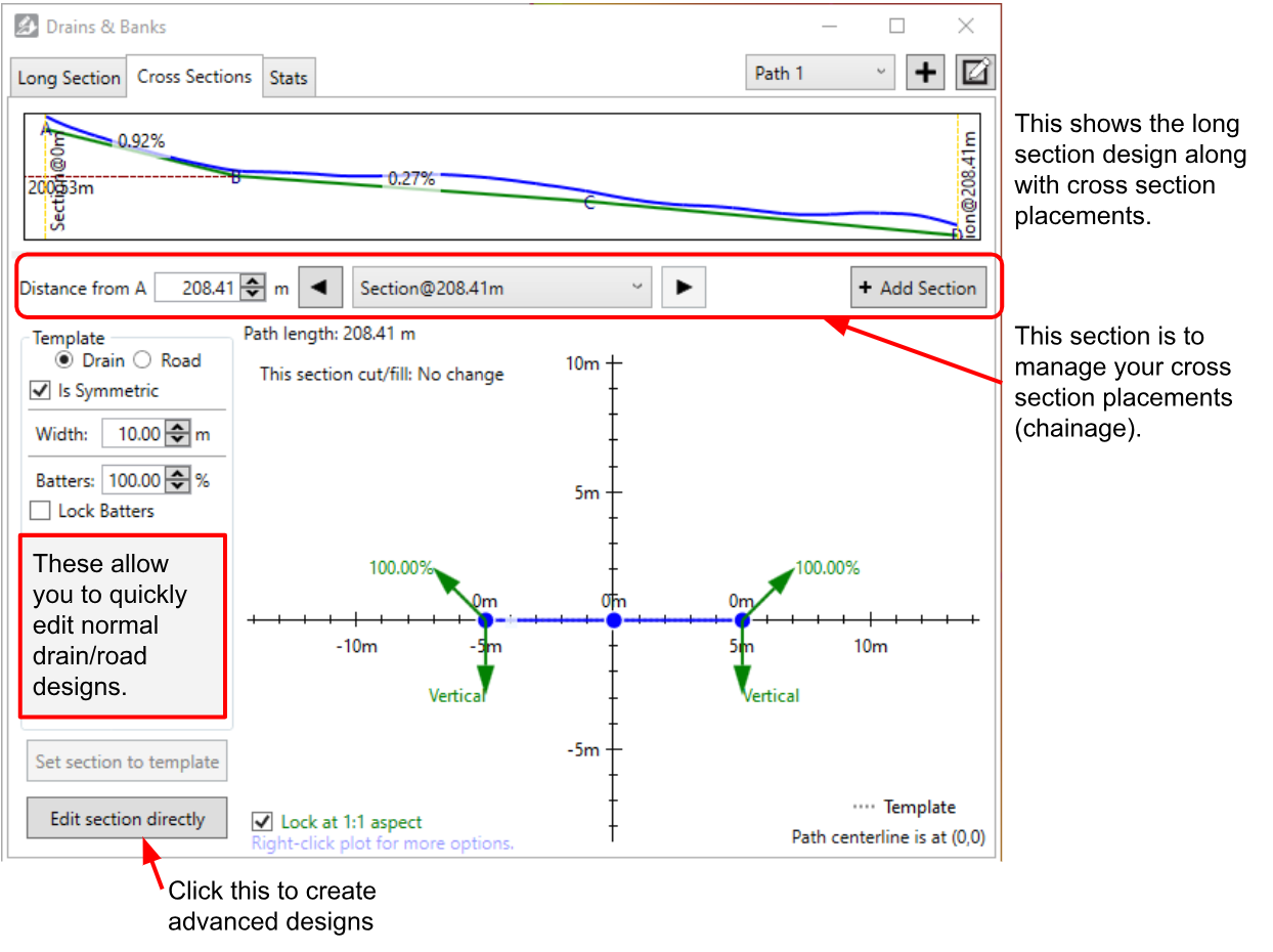
A game-changing feature of this tool is the ability to set multiple profiles along the path. This allows you to create a drain that has a small width at the head and then progressively gets wider all the way to the end. This can dramatically reduce the earthworks to implement. You can add as many sections as you want, and it will smoothly transition between each of them.
NOTE: The green batter arrows on the end indicate that the algorithm will follow that angle until it reaches the surface - going at a constant slope until it does.
Working with advanced cross section designs
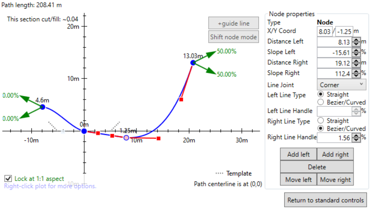
Advanced cross section designs allow you to create custom profiles, but take a bit more work. The plot shows where the profile is relative to the longitudinal line. The longitudinal line’s position is at 0,0 (where the two black axes meet).
A VERY important concept is that 0,0 (where the two plot axes meet) is the same elevation as the longitudinal design (green line). If you don’t go through 0,0 then you will be effectively modifying the long section design. This is very useful in some circumstances, however, it can bite you (if you raise one cross section too high, it may make the drain go uphill for a bit and pool water).
How to edit advanced cross sections
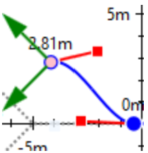 You can either create your profile by just clicking and dragging the cross section line around, or you can use the properties tab on the right. The selected node appears pink so you can easily identify it. The clicking UI is the same as other places you edit lines. Click on the line to add drag handles, right-click to remove handles, click and drag to move handles.
Cross sections can be linear or curved. Curved segments are created with curves called beziers. To use them, click on a point and two red drag handles will appear. The red lines with handles show the tangent of their attached node, allowing you to set up a smooth (or not!) transition. This feature can really help when implementing with a T3RRA-enabled bulldozer (where you mainly push across cross sections rather than longitudinally).
Adding guide lines
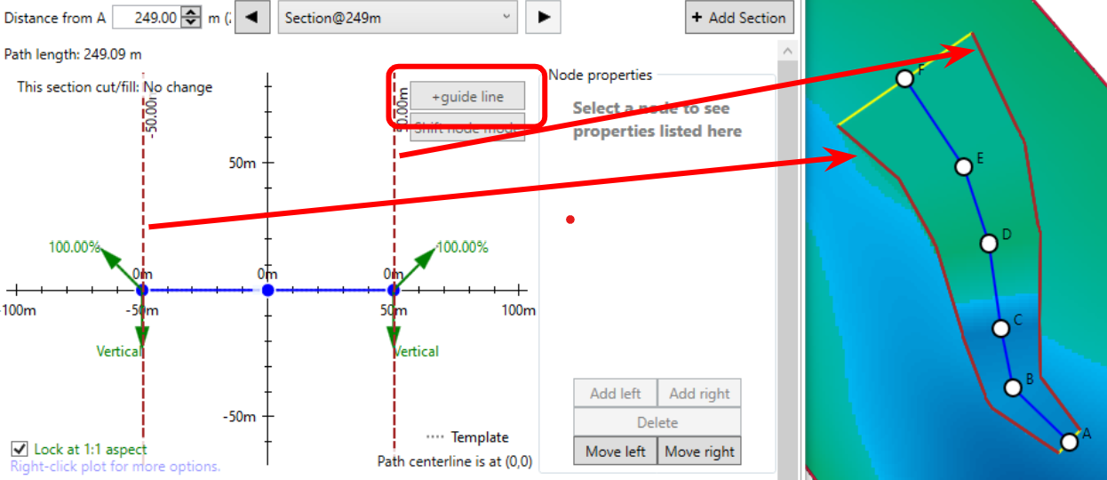
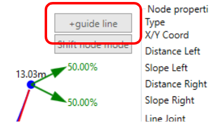 Guide lines were added so you can export guidance lines (e.g. as John Deere Adaptive Curves). To create guide lines, you must be in in the advanced design tools, and then you can click the “+guide lines” button. It will add a vertical line that you can drag left and right to position. To remove a guide line, right-click on it.
If you have created multiple cross sections, add guide lines to each cross section. If you have the same number of guide lines in each cross section, they will join up. That way you can vary the sideways position of your guide lines along the drain (e.g. for finishing). Below is an example of going from 20m between the guide lines at the South end to 100m at the North end.
Cross section batters
A concept that is a bit confusing is the batters on the sides of the cross section (the green arrows). They tell the algorithm how to join up with the existing surface. If the profile would end beneath the surface, it will follow the angle shown in the upwards facing arrow, and the opposite is true if it ends above the surface. This means that you can easily design a profile that is both cutting and filling, with the batters allowing it to smoothly transition in either case.
Positioning nodes relative to the surface - Fixed width batters
Sometimes when designing a drain or road, the available width is limited by adjacent fields or structures. In these cases, a traditional batter (with a constant grade) is inappropriate. Rather than a fixed slope batter, a fixed width batter would be fitting. This can be achieved with a new feature; Nodes in a cross section can now set their elevation relative to the surface instead of the long section (as previously). This facilitates more design possibilities than just fixed width batters - such as covering over divots and depressions at an angle, feathering regions edges, and having roads with drains at a fixed distance from them.
To use surface-relative nodes to create a cross section with a ‘fixed width batter’, add a node at the start of the batter and a node at the end of the batter (where the cross section should meet the surface). Select the node at the end of the batter and change the “Y relative to” drop down to Surface. When “Surface” is selected, the Y value should be zero. Changing the Y value from zero will make the cross section go to above (positive) or below (negative) the surface.
Because nodes relative to the surface require a surface to determine their elevation, a drain may not apply as you expect near the edge of a surface. If this happens to you, you may want to expand the surface, or switch back to Long Section temporarily and update the Y value there (make sure you switch back to being relative to the Surface).
NOTE: Any bumps and anomalies in the surface where the surface-nodes go over will translate into ‘frills’ or oscillations in the applied drain surface that look like washboarding. We recommend applying a design or light smooth over the affected areas to reduce these variations.
Working with multiple paths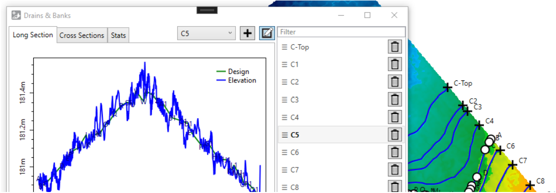
The section at the top right of the window allows you to change the working path. Click the “+” button to add a new line. Clicking the edit button on the far right will let you rename and reorder the paths so you can more easily understand which is which. The names of the paths are depicted on the map image, further making it easier to determine which path is which.
All the tabs apply to just the selected path, so when you’re working on multiple paths you will need to make sure you design all paths one by one.
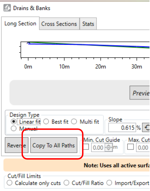
NOTE: If you want to copy your current design (both long section and profiles) you can click “Copy To All Paths”. This copies design parameters (except for manual elevation edits), and cross sections to the other paths.