Importing a Surface from an Existing Elevation Surface
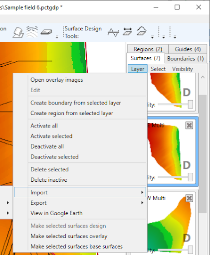
By working in the Surface Tab in the Layers Panel, select: Layer > Import > From existing elevation surface:
 PCT Image elevations (*.pcti)
- USGS DEM elevations (*.dem)
- Space Shuttle Radar Topography
- SRTM1 elevations (*.hgt)
- SRTM3 elevations (*hgt)
- SRTM30 elevations (*.dem)
- Generic XYZ elevations (*.xyz)
- DXF (*.dxf)
- Gridded DXF elevation points (*dxf)
- DXF 3d Faces (*.dxf)
- DXF PolyFaceMesh (*dxf)
- LandXML surface (*.xml)
- JSONGrid elevations (*jsongrid)
- Surfer grid elevations (*.grd)
- Esri ASCII elevations (*.asc)
- UK LIDAR (OSGB 1936 / British National Grid (*.asc)
- Trimble Field Level II (*.gps)
- Ezigrade surfaces (*.ezigrade)
Examples of Importing a Surface from an Existing Elevation Surface
File Type: DXF Surface
DXF files are a standard format used by civil designers, with file names that end in “.dxf”. They can contain all manner of drawings and text in 2D and 3D. Because of this, they are not georeferenced and require you to know the georeference information. They can be exported from all civil CAD programs. We support importing surfaces from DXF, but also linework and markers.
NOTE: DWG is a file format related to DXF. If you encounter a DWG, we recommend you request your designer to re-export it as a DXF. It is possible to convert most DWG to DXF with free tools like “DWG DXF Converter” by AnyDWG Software (available in the Windows Store). However, the quality of the conversion is not guaranteed.
To Import a DXF Surface:
From the Surface Tab in the Layers Panel, select: Layer > Import > From existing elevation surface > DXF (*.dxf)
Select the relevant option from the below list:
- DXF 3D Faces (*.dxf)
- NOTE: If you are not sure, choose this, as it is the most common option.
- It is when you have triangulated points to create an elevation surface.
- Gridded DXF elevation points (*.dxf)
- Is a grid of regularly spaced points with no triangles between them.
- DXF PolyFaceMesh (*.dxf)
- This is an uncommon alternative mesh format, usually with a mesh composed of squares.
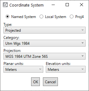 This coordinate system selection window will then appear. Since projection information is not included in DXF files, you will need to select it now. This tells the importer how to correctly interpret the X, Y and Z coordinates as locations on the Earth.
Common selections include:
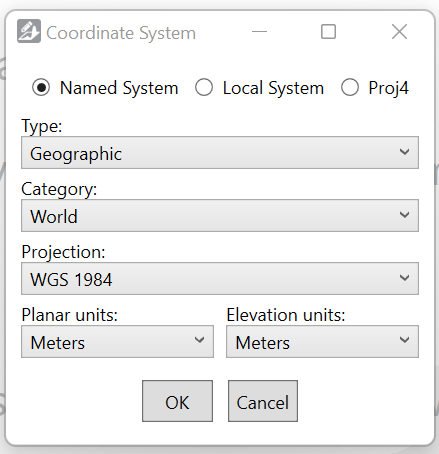
- WGS84 (longitudes and latitudes) is under:
? Named System
> Type: Geographic
> Category: World
> Projection: WGS 1984. - UTM Zone projections are (see screen capture for an example):
? Named System
> Type: Projected
> Category: UTM Wgs 1984. - Map Grid of Australia projections are under:
? Named System
> Type: Projected
> Category: National Grids Australia. - State Planes are under:
? Named System
> Type: Projected
> Categories like State Plane Nad 1983 Feet.
NOTE: Be sure to select the correct planar and elevation units from the dropdown menus for your data too.
A local system is a custom coordinate system, and you will need the reference longitude and latitude, the location of the reference point locally, and the local system type (e.g. Orthographic).
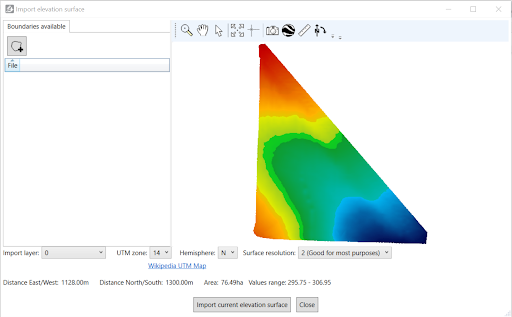
After selecting ‘OK’, the ‘Import elevation surface’ screen will pop up. Ensure you select the appropriate pixel size (in the lower right of the window) for the type of work you are doing, but remember that smaller pixel sizes produce larger files that take longer to process. If there are multiple layers in the file, you can select them with the drop-down in the lower left of the window.
At this point, it is recommended that you verify the projection was correct by opening it in Google Earth.
NOTE: You must have Google Earth Pro installed on your computer to do this.
To export it to Google Earth:
> Select the Google Earth icon in the toolbar.
> Enter a name and click OK
> Compare the elevation map’s location to the satellite imagery. If the projection is correct, it should line up pretty well with field boundaries and landmarks.
In the ‘Import elevation surface’ window there are several options:
- Import boundary - This allows you to import only a part of the field. You can draw a boundary polygon in Google Earth, export it as KML, then import it here. Note that a path (like a polyline) is not a valid boundary - it has to be a polygon.
- Import layer - Select which layers to import. Some files contain more than one surface layer.
- UTM zone and Hemisphere - For new projects, when your field crosses a UTM boundary or hemisphere, you can choose which UTM Zone it is imported into.
- Surface resolution - Read the descriptions for each pixel size to help you choose appropriately.
NOTE: The lower the surface resolution, the longer the import will take to complete.
File Type: LandXML Surfaces (*.xml)
LandXML is a non-proprietary file format created in 2000 to facilitate the interchange and archival of elevation models and other related survey and civil engineering data.
To Import a .XML Surface:
> From the Surface Tab in the Layers Panel, select: Layer > Import > From existing elevation surface > LandXML Surfaces (*.xml) > Select the relevant file
A ‘Coordinate System’ pop-up box will appear. (Is this information pre-populated based on the file or will changes need to be made?)
Once you select the relevant details in the pop-up window above, select ‘OK.
Here you will see a ‘Import elevation surface’ pop-up window. There will be instructions (shown in RED) to choose the hemisphere for this data. Once selected, you will also need to select the UTM zone as well.
File Type: Trimble Field Level II (*.gps)
.gps files are used in Trimble FMX and TMX displays
To Import a .GPS Surface:
> From the Surface Tab in the Layers Panel, select: Layer > Import > From existing elevation surface > Trimble Field Level II (*.gps) > Select the relevant file

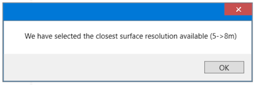
A box will appear stating which surface resolution has been selected based on the file you are importing.
At this point, it is recommended that you verify the projection was correct by opening it in Google Earth.
NOTE: You must have Google Earth Pro installed on your computer to do this.
To export it to Google Earth:
> Select the Google Earth icon in the toolbar
> Enter a name and click OK
> Compare the elevation map’s location to the satellite imagery. If the projection is correct, it should line up pretty well with field boundaries and landmarks.
In the ‘Import elevation surface’ window there are several options:
- Import boundary - This allows you to import only a part of the field. You can draw a boundary polygon in Google Earth, export it as KML, then import it here.
- Import layer - Select which layers to import. Some files contain more than one surface layer.
- UTM zone and Hemisphere - For new projects, when your field crosses a UTM boundary or hemisphere, you can choose which UTM Zone it is imported into.
- Surface resolution - This will be preselected (see above) during the import process.
NOTE: The lower the surface resolution, the longer the import will take to complete.
 Once you are happy with the above surface and selections, press ‘Import current elevation surface’. A pop up window will appear:
This then imports that surface into the working area of T3RRA Design Plus, while still keeping the ‘importer’ running. You can either close out of the Importer or import more surfaces if required. It will also import the linework and master benchmark (MB) into Guides. These can be included in a .gps export to ensure it has the same reference point.