Machine Tab
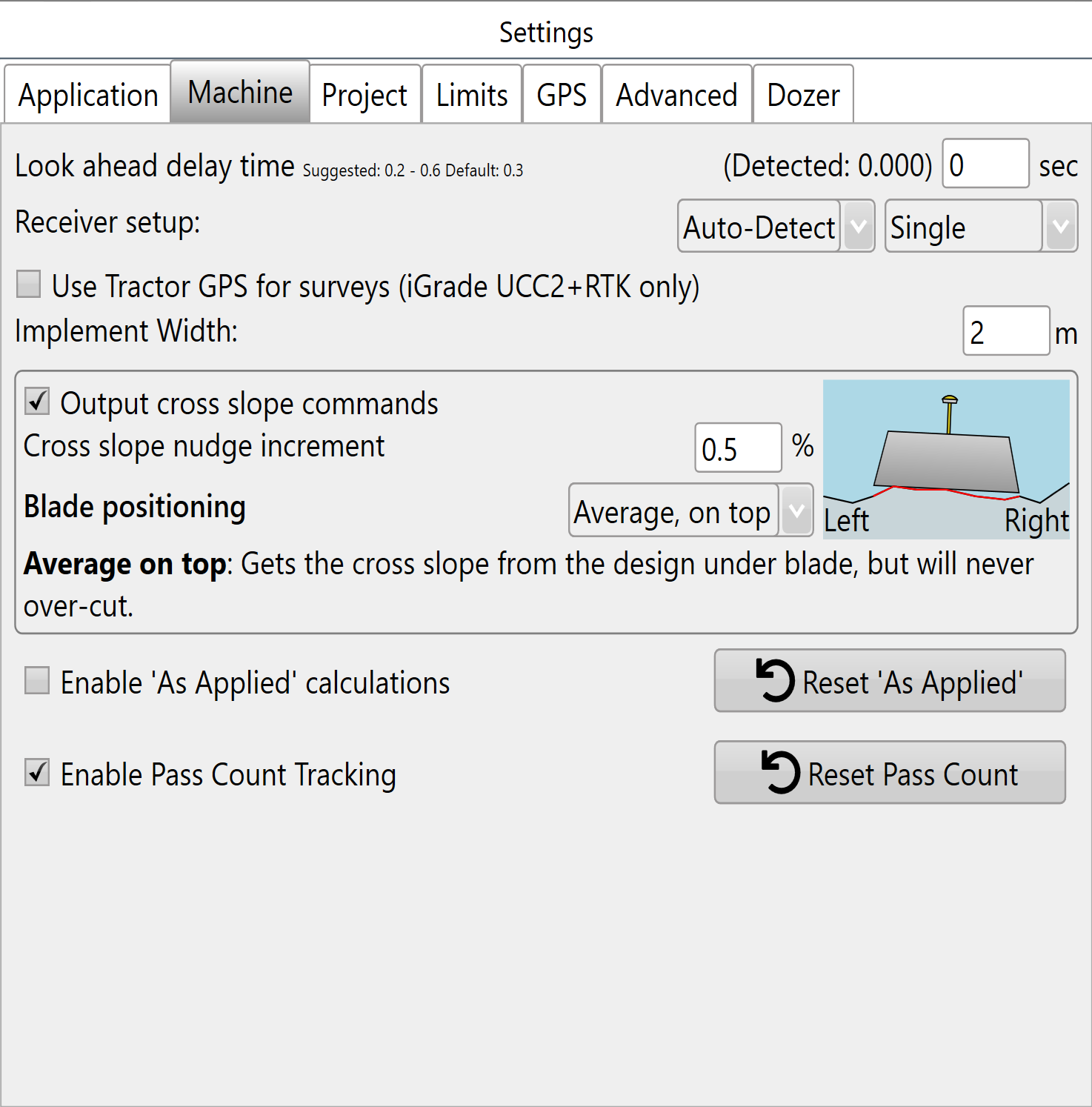
Look ahead delay time - In order to control blade height the software must receive an elevation from iGrade™, process that elevation, and then return a control signal to iGrade™. This control loop is quick but the time delay can cause inaccurate implementation in certain situations.
A normal “Look ahead” time is 0.3 to 0.5 seconds. The exact time is machine specific and can be determined through experimentation (see Bi-Directional error in T3RRA in the troubleshooting section). The look ahead time helps to account for the delay in the control loop.
If the look ahead time is not set the delay can cause a “bi-directional error”. This is where the blade offsets incorrectly, moving up when going down a slope and down when going up a slope. This error occurs consistently. If the look ahead time is set too LOW the implement will always grade high when going down-slope and low when going up-slope, the opposite effect will occur if the look ahead time is set too HIGH. Bi-directional error is most noticeable when working steep slopes at higher speeds.
Receiver setup - The 2 drop down menus set which sort of receiver connection is being used(left) and the number of receivers that are connected (right).
The receiver connection type in the left drop down menu has 4 options:
- Auto-detect (default)
- Non-IGrade
- IGrade 1
- IGrade 2
The number of receivers (Implements) can be adjusted using the right drop down menu:
- Single
- Dual implements
- Two receivers on one implement
- Triple implements.
T3RRA will use the front GPS receiver for any multi-bucket configuration, and both GPS receivers when set to "two receivers on the one implement".
When using multiple receivers, iGrade™ has the ability to control SCV1 and SCV3. Ensure SCV1 and SCV3 are configured correctly for remote control commands by placing them in detent, for information on how to do this refer to “How we work with iGrade™”.
 When utilising dual or triple scrapers on UCC2 you may need to adjust the receiver height settings in the receiver settings in the individual receiver menu in ISO Page. Refer to your iGrade Manual for instructions on adjusting individual receiver height offsets. When using multiple scrapers with UCC1, the receivers must be mounted at the same height above the blade. Also with UCC1, implement offsets cannot be entered in the display to account for mounting error.
NOTE: To lower the blade enter a higher receiver height. To raise the blade position lower the height set in the receiver setup.
'Use Tractor GPS for surveys' - Only available with iGrade UCC2. When selected, the Tractor GPS will be used for surveying when it has RTK. Otherwise, it will fall back to standard operation.
Implement width - This value reflects how wide the implement in use is and needs to be entered manually. This value is needed for ‘Cross slope’, ‘As applied’ and ‘Pass count’.
Implement settings:
Output cross slope commands - The amount each tap of the manual left/right cross slope adjustment buttons causes the cross slope to change by during implementation. Uses percentages (not degrees).
Cross slope nudge increment - This specifies the incremental amount each press of the left and right tilt buttons will add to the cross slope.
Blade positioning - Allows the operator to specify which part of the soil profile under the blade has priority in determining blade position. This option is only available when you have entered an ‘Implement width’ and enabled to ‘Output cross slope commands’.
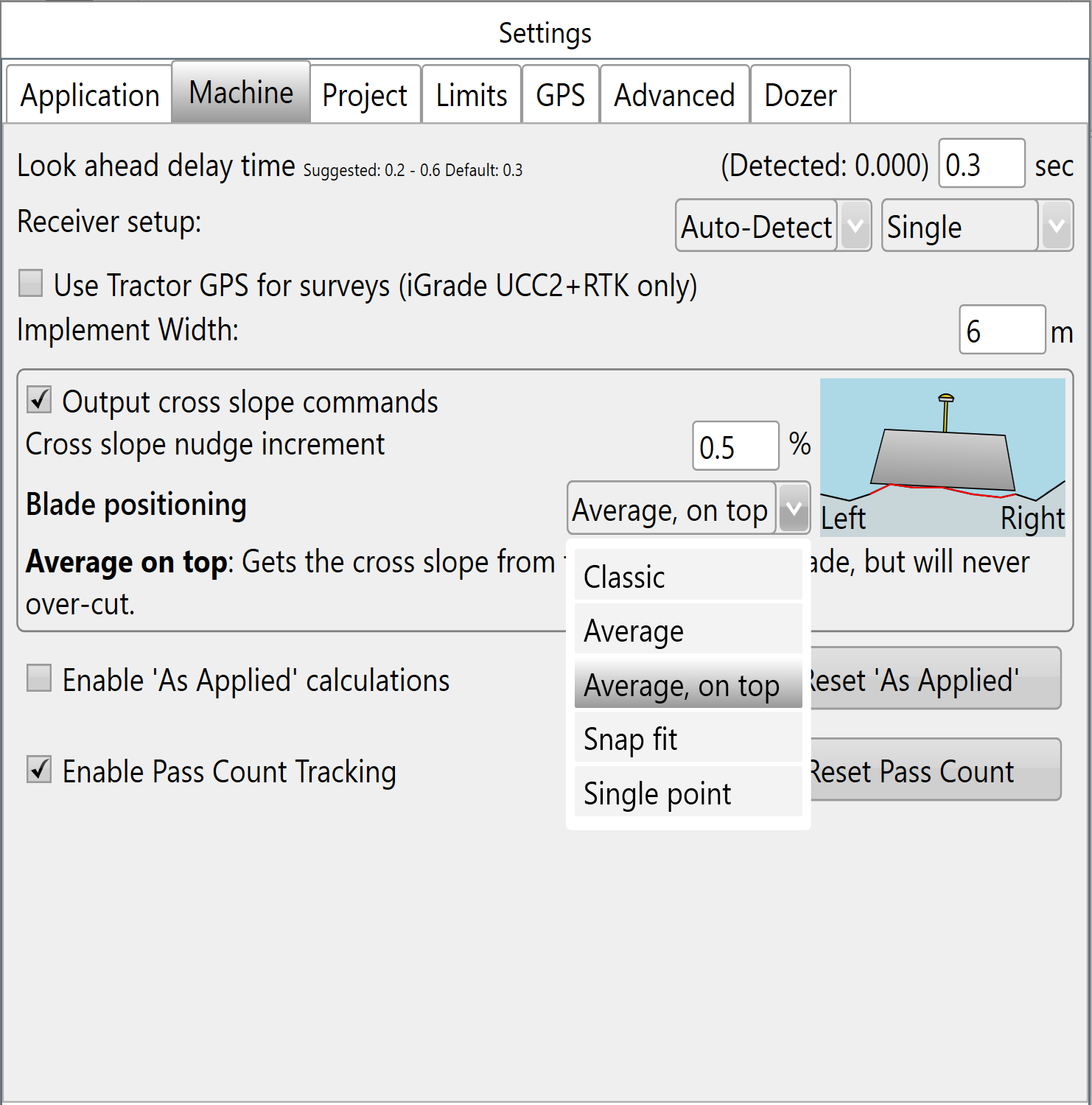
Classic - This position uses the design elevation as the target elevation under the center of the blade, and the cross-slope is determined by the design elevations under the left and right points of the blade. With Classic, it is easy to over-dig when driving down the midline of ditches, or to clip the top off a bank when straddling the ridge.
Average - This position looks at the design surface under the blade and goes for the overall trend. This is great for taking any full-field design and giving you basically that. It’s not so good for abruptly changing slopes, however.
Average, on top - This position is one step up from the trend method, literally. It determines the slope in the same way as the ‘Average’ method, but it always avoids overcutting.
Snap fit - This position attempts to find the best blade position, without overcutting. If you are going over a break line, you will see the blade snap from one position to the other as you traverse the break line. What it means, though, is that you will be cutting and filling most efficiently, minimising the number of passes and risk of rework. This option has been tailored for abruptly changing slopes.
Single point - This position is what everyone seems to want − Control-by-point. In this configuration, you pick a position on the blade represented by the red arrow. That point on the blade will be at the design elevation and cross slope even if it cuts below the design elsewhere. This is envisioned to be great for digging features like V-ditches.
Enable As-applied calculations - As-applied calculations show a graphic representation of the surface's current state as work progresses. For more see Understanding how “As-applied” works
NOTE: ‘Implement width’ is required to enable the As-applied feature.
Enable Pass Count Tracking - Pass count tracking shows how many times you have gone over a particular spot, an indication of the amount of work that has been done in an area. For more see Understanding how “Pass Count” works
NOTE: ‘Implement width’ is required to enable the Pass Count Tracking feature.
Note: ‘Enable As-applied calculations’ and ‘Enable Pass Count Tracking’ are set to for each system, if a different Cutta system is used your setting won’t be remembered.
Find below answer to some frequently asked questions regarding implement profiles: