
7.1 | Appearance
The Appearance page allows you to customise how Level COMMAND is displayed. These settings only affect the user interface and map presentation—they do not change how the guidance or automatic control system operates.
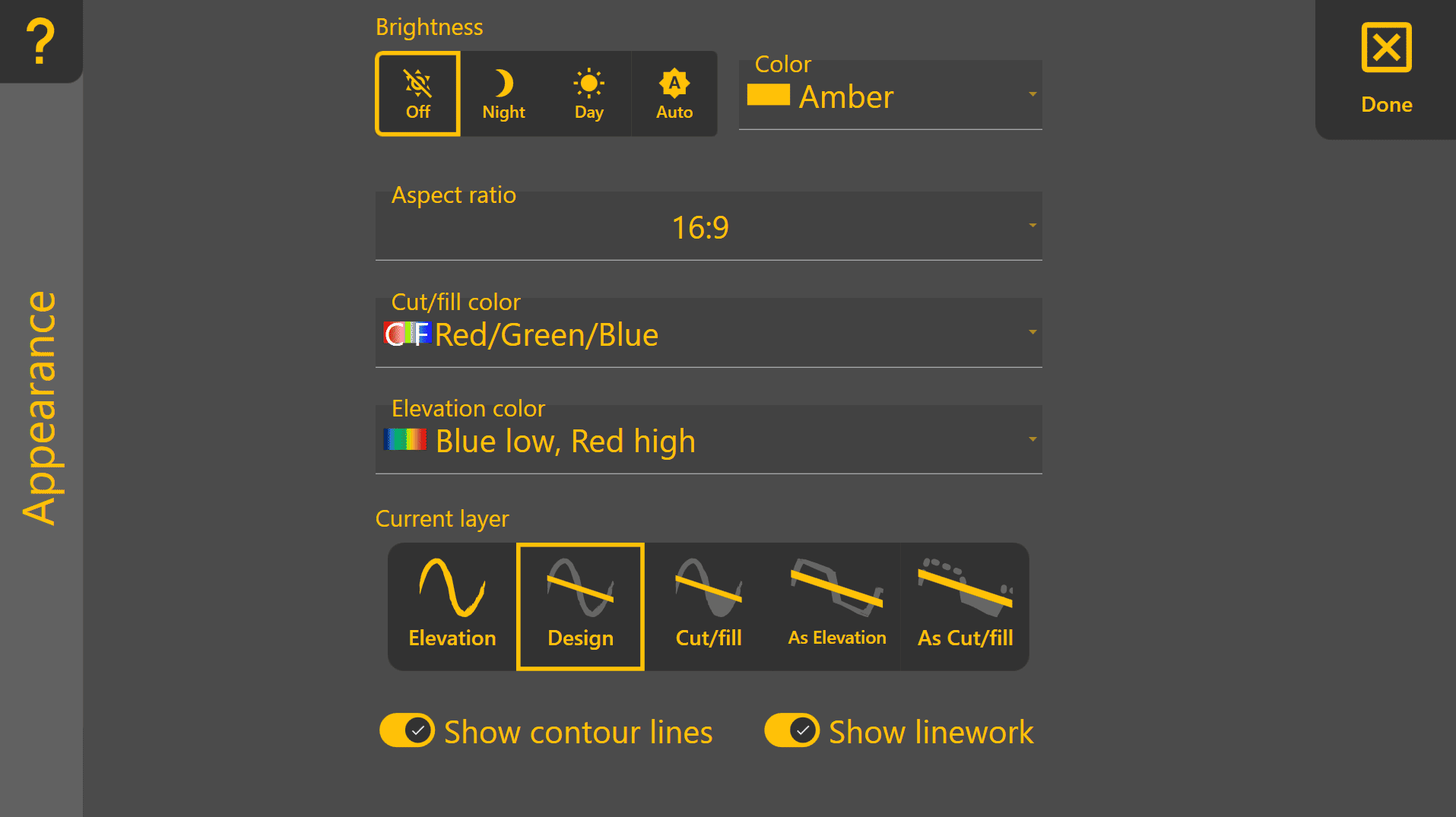
Brightness
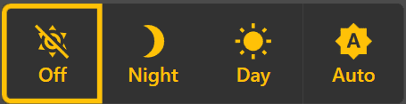
Adjusts the display brightness to suit different lighting conditions.
- Off – Level COMMAND does not control screen brightness.
- Night – Reduces brightness for comfortable viewing in low-light conditions.
- Day – Sets the display to maximum brightness.
- Auto – Automatically adjusts brightness based on the current time and location, dimming at sunset and brightening at sunrise.
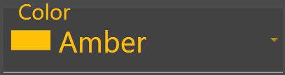 Theme Colour

Selects the primary colour used throughout the Level COMMAND interface.
Aspect Ratio
Optimises the interface layout for your display.
Select the aspect ratio that best matches your device:
- 16:9
- 16:10

Cut/Fill Colour Scheme
Selects the colours used to display Cut/Fill maps.
Two colour schemes are available:
- Magenta / Green – Magenta represents cut areas and green represents fill areas.
- Red / Green / Blue – Red represents cut, green represents on-grade, and blue represents fill.
The Magenta / Green scheme may be easier to distinguish for some users with red-green colour vision deficiency, while Red / Green / Blue provides a clearer visual indication of areas already on grade.

Elevation Colour Scheme
Changes the colour palette used to display elevation maps.
Different colour schemes may improve visibility depending on personal preference or lighting conditions.

Current Map Layer
Selects which project layer is displayed on the map.
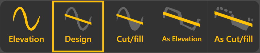
Available layers include:
- Elevation – Displays the original surveyed ground surface before any earthworks have been carried out.
- Design – Displays the design surface that the machine is working towards.
- Cut/Fill – Shows where material must be cut or filled relative to the original elevation surface.
- As Elevation – Displays the measured surface as work progresses, providing a live representation of completed earthworks. Contour lines are not displayed for this layer.
- As Cut/Fill – Displays the remaining cut and fill required by comparing the current surface with the design surface. Contour lines are not displayed for this layer.
Show Contour Lines

Enables or disables contour lines on supported map layers.
Contour lines are available for Elevation, Design, and Cut/Fill layers. They are not shown for As Elevation or As Cut/Fill, as these layers update continuously while work is being performed.
Show Linework

Shows or hides imported project linework on the map.
Turning linework off can simplify the display when working with projects containing a large number of lines or boundaries.