
2.1 | System Architecture
Level COMMAND continuously determines the machine's position, compares it to the design surface and calculates the implement movement required to achieve the desired grade.
Theory of Operation
Level COMMAND is a closed-loop terrain-control operating environment that continuously compares the machine’s measured terrain position against the active design surface or plane in order to determine the required implement movement.
The system operates together with the COMMAND hardware platform, GNSS receivers, hydraulic interfaces, machine sensors, and operator inputs to provide terrain guidance and automatic implement control.
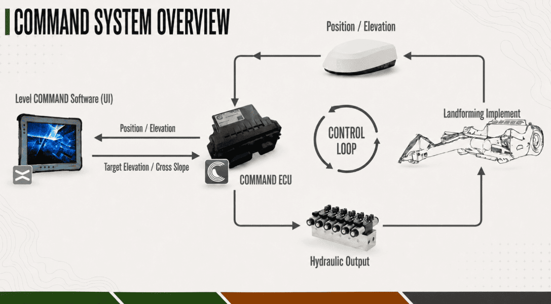
During operation, Level COMMAND continuously processes:
- GNSS position data
- Machine and receiver offsets
- Active design surfaces or planes
- Machine configuration information
- Operator-applied offsets and limits
- Vehicle movement and speed information
Using this information, the system calculates target elevations and control corrections which are transmitted to the COMMAND ECU for hydraulic or vehicle interface control.
The operator remains responsible for supervising machine behaviour and safe operation at all times.
Position & Elevation Processing
GNSS receivers are mounted at known positions relative to the controlled implement. Level COMMAND applies configured machine and receiver offsets to calculate the position of the controlled point relative to the terrain surface.
Using the calculated controlled-point position, the system determines:
- Current Height
- Design Height
- Target Height
- Cross-slope or tilt requirements where applicable
These values are used to determine the required implement correction relative to the active design surface or control mode.
Configured machine geometry and positional offsets are applied before hydraulic commands are transmitted to the COMMAND ECU to ensure implement movement corresponds correctly to the controlled point position.
Predictive Control (Look Ahead)
Hydraulic systems and machine movement introduce a delay between terrain measurement and implement response.
To improve grading accuracy during movement, the system uses predictive positioning behaviour referred to as Look Ahead.
Look Ahead estimates the future position of the controlled point based on current machine speed and configurable control response timing. Target elevations are then calculated ahead of the machine’s current position to reduce tracking lag and improve terrain-following performance.
Look Ahead settings may be adjusted during commissioning and advanced diagnostics procedures.
Blade Shift & Control Limits
Material movement requirements may exceed the desired cut or fill amount achievable in a single grading pass.
Blade Shift allows operators to temporarily offset the target elevation relative to the active design surface without modifying the underlying project data.
Additional control limits may also be applied to restrict:
- Maximum cut depth
- Maximum fill height
- Cross-slope correction
- Hydraulic response behaviour
- Automatic control engagement conditions
These limits assist in maintaining stable machine behaviour and predictable terrain outcomes during automatic control operation.
Off-Surface Behaviour
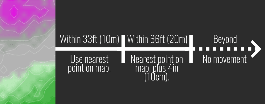
Automatic control operation requires valid design surface data. If the machine moves outside the available design surface area, the system may suspend automatic control movement commands until valid surface data becomes available again. Automatic control resumes as the implement approaches the design surface again.
This behaviour prevents unintended implement movement when operating beyond the active design boundary.
Manual & Automatic Control Modes
Level COMMAND supports both manual and automatic implement control operation.
Manual Control Mode
When automatic control is Disengaged, hydraulic movement remains under direct operator control using tractor SCVs, joysticks, or other configured control inputs.
In Manual Control Mode, the system continues to display terrain, project, and elevation information but does not actively control hydraulic outputs.
Armed State
When the system is Armed, the COMMAND ECU is enabled and prepared to assume automatic control once engagement conditions are satisfied.
While Armed, manual hydraulic control remains available to the operator. The Armed state allows the system to monitor positioning and control conditions while preventing automatic hydraulic actuation until automatic control is Engaged.
Automatic Control Mode
When automatic control is Engaged, the system continuously calculates implement corrections relative to the active design surface or plane.
The COMMAND ECU then controls hydraulic outputs using:
- Current terrain position
- Target elevation
- Cross-slope targets where applicable
- Control calibration parameters
- Tracking sensitivity settings
- Acquire and tracking thresholds
Depending on machine configuration, manual hydraulic input may temporarily override automatic control or disengage automatic control operation. Automatic control may be disengaged at any time using the configured disengagement controls or Arm/Engage switch.