
3.2 | Machine Tab
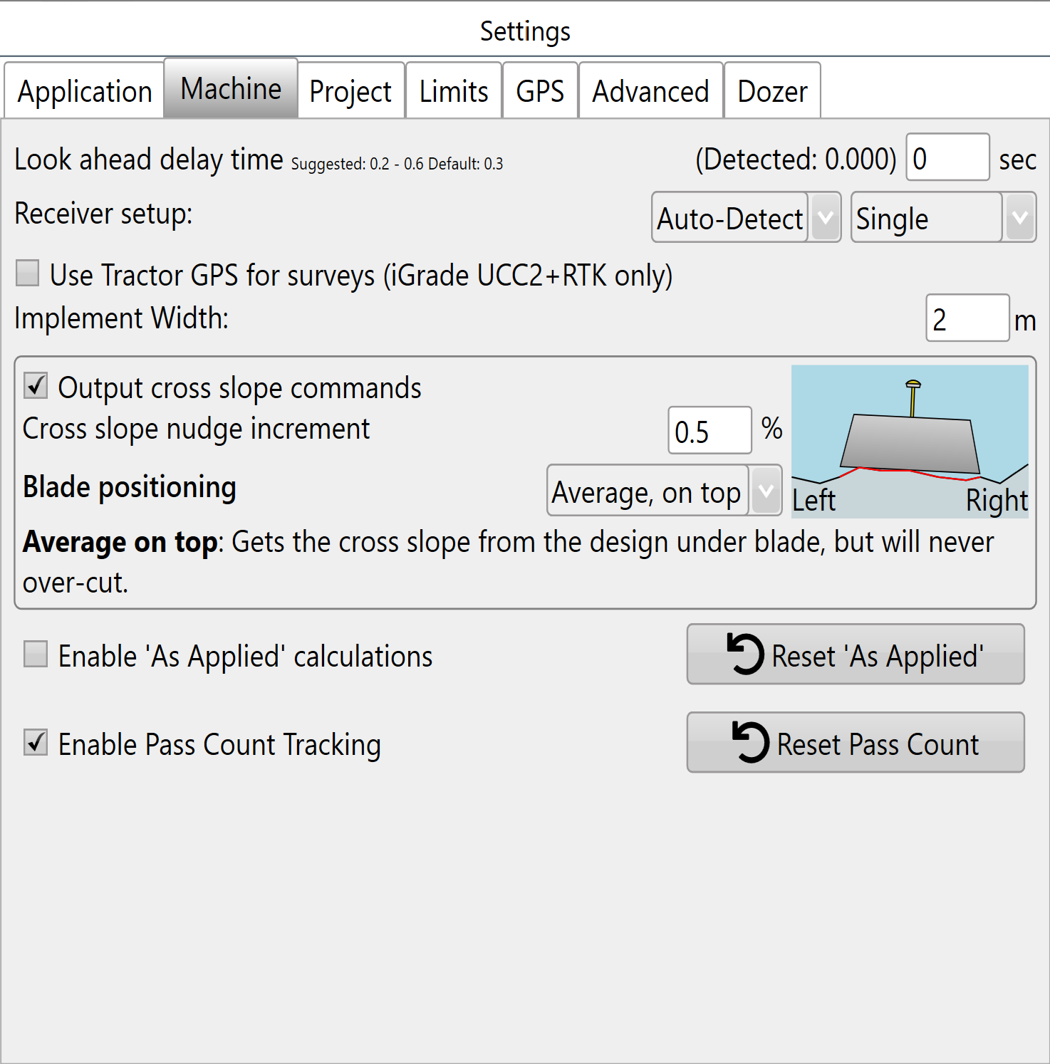
Look ahead delay time
To control blade height, the software receives an elevation from iGrade™, processes it, then returns a control signal to iGrade™. Although this control loop is quick, its delay can cause inaccurate implementation in some situations.
A normal “Look ahead” time is 0.3 to 0.5 seconds. The exact time is machine specific and can be determined by experimentation; see Bi-Directional error in T3RRA in the troubleshooting section. Look ahead time helps account for the control-loop delay.
If look ahead time is not set, the delay can cause a consistent “bi-directional error”: the blade offsets incorrectly, moving up when travelling down a slope and down when travelling up a slope. If the time is too LOW, the implement always grades high down-slope and low up-slope; if it is too HIGH, the opposite occurs. Bi-directional error is most noticeable on steep slopes at higher speeds.
Receiver setup
The two drop down menus select the receiver connection type on the left and the number of connected receivers on the right.
The left receiver connection menu offers four options:
- Auto-detect (default)
- Non-IGrade
- IGrade 1
- IGrade 2
Use the right drop down menu to adjust the number of receivers (Implements):
- Single
- Dual implements
- Two receivers on one implement
- Triple implements.
T3RRA uses the front GPS receiver for any multi-bucket configuration, and both GPS receivers when set to “two receivers on the one implement”.
When multiple receivers are used, iGrade™ can control SCV1 and SCV3. Place both SCV1 and SCV3 in detent so they are configured correctly for remote control commands. See How we work with iGrade™ for instructions.

For dual or triple scrapers on UCC2, you may need to adjust receiver height settings in the individual receiver menu in ISO Page. Refer to your iGrade Manual for instructions on individual receiver height offsets. With multiple scrapers on UCC1, receivers must be mounted at the same height above the blade. UCC1 does not allow implement offsets to be entered in the display to account for mounting error.
NOTE: To lower the blade, enter a higher receiver height. To raise the blade position, lower the height set in receiver setup.
Use Tractor GPS for surveys
Use Tractor GPS for surveys is available only with iGrade UCC2. When selected, Tractor GPS is used for surveying when it has RTK; otherwise, the software falls back to standard operation.
Implement settings
Implement width is the width of the implement in use and must be entered manually. It is needed for ‘Cross slope’, ‘As applied’ and ‘Pass count’.
Output cross slope commands specifies how much each tap of the manual left/right cross slope adjustment buttons changes cross slope during implementation. It uses percentages, not degrees.
Cross slope nudge increment specifies the incremental amount each press of the left and right tilt buttons adds to cross slope.
Blade positioning
Blade positioning specifies which part of the soil profile under the blade has priority in determining blade position. This option is available only after you enter ‘Implement width’ and enable ‘Output cross slope commands’.
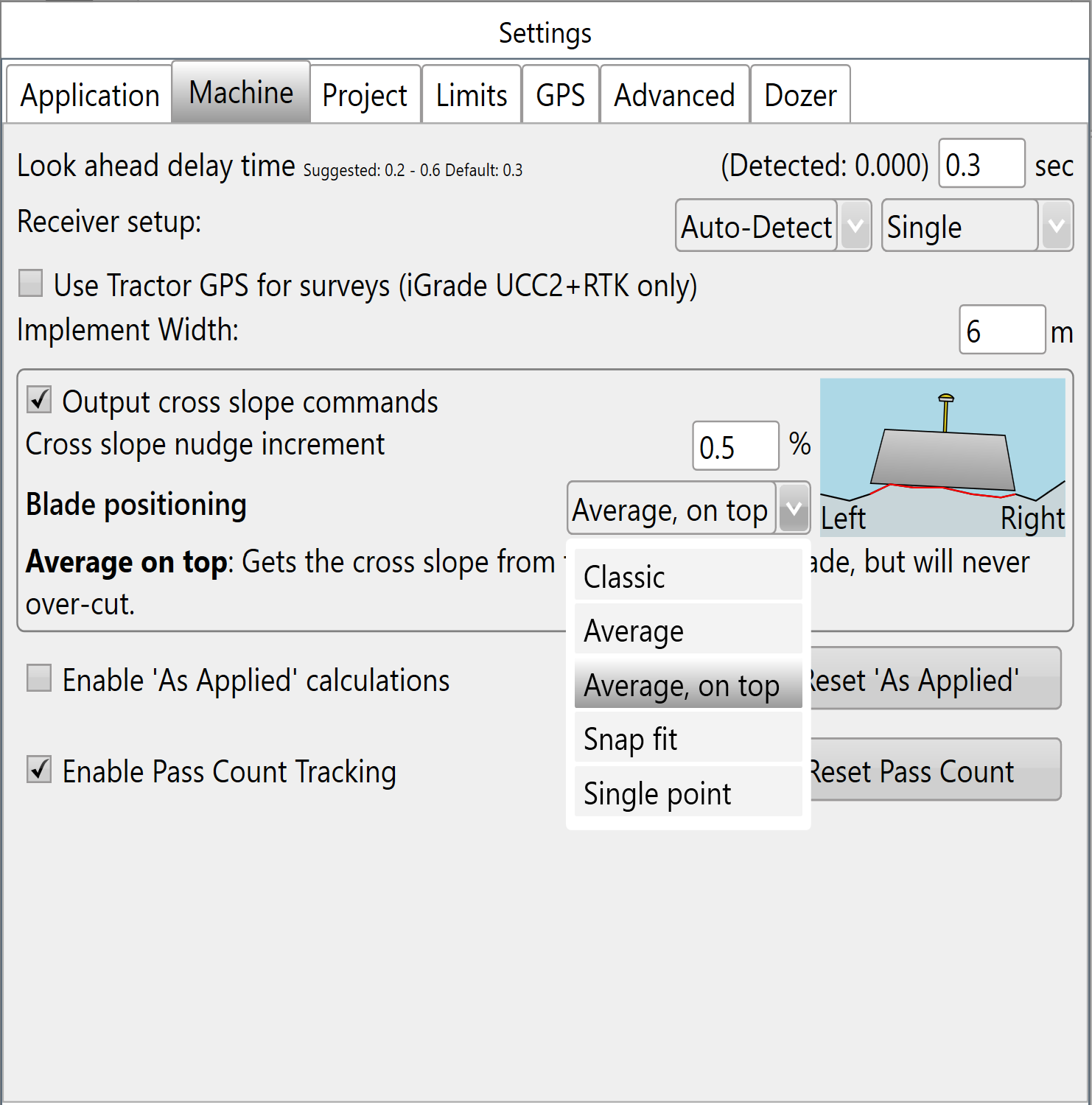
Classic uses the design elevation as the target under the blade centre. Cross-slope is determined by design elevations under the left and right blade points. This makes it easy to over-dig down the midline of ditches or clip the top off a bank when straddling its ridge.
Average follows the overall trend of the design surface under the blade. It works well for reproducing a full-field design, but is less suited to abruptly changing slopes.
Average, on top determines slope in the same way as Average, but positions the blade above that trend to always avoid overcutting.
Snap fit attempts to find the best blade position without overcutting. As you traverse a break line, the blade snaps from one position to another. This is intended to cut and fill most efficiently, minimising passes and rework risk, and is tailored for abruptly changing slopes.
Single point provides Control-by-point: choose a blade position represented by the red arrow. That point follows the design elevation and cross slope even if the blade cuts below the design elsewhere. This is envisioned to work well for features such as V-ditches.
As-applied and Pass Count tracking
Enable As-applied calculations shows a graphic representation of the surface’s current state as work progresses. See Understanding how “As-applied” works.
NOTE: ‘Implement width’ is required to enable the As-applied feature.
Enable Pass Count Tracking shows how many times a particular spot has been covered, indicating the amount of work done in an area. See Understanding how “Pass Count” works.
NOTE: ‘Implement width’ is required to enable Pass Count Tracking.
Note: ‘Enable As-applied calculations’ and ‘Enable Pass Count Tracking’ are set for each system. Your settings will not be remembered if you use a different Cutta system.
Implement profile questions
Frequently asked questions about implement profiles:
Everyday blade clearance
Question: Is it a requirement for everyday implementation to fill in Maximum blade clearance even if you are NOT choosing/entering an Implement Profile?
No. It is an organisational tool for a more efficient workflow.
Does “Project profile” reflect the Maximum blade clearance entered?
The saved Implement profile reflects all parameters entered for that profile.
RTK base station
Question: Am I required to use the same RTK base station for surveying and implementing (I will be using the same implement)?
To benefit from the Implement profile Maximum blade clearance tool, it makes most sense to use the same tractor, implement and GPS base.
Can this be used with Auto Drains and Pattern Drains?
Yes, if you surveyed with the same equipment you are implementing with.
How do I disable this setting?
Selecting a saved profile is the best way to know that you are using the Implement Profile settings for that equipment. It does not make sense to disable an implement profile, because its settings are always required.
Multiple implements and SCVs
Question: When pulling multiples, does this apply to only the implement using SCV 1? 2? 3?
Maximum blade clearance refers to the implement using SCV 1.
Setting zero for other drains
Question: Do I need to set zero at the first drain and then I will not need to set zero again when digging the other drains?
Not if you selected a saved profile and surveyed and implemented with the same equipment. You must have entered or calculated the proper blade clearance.
Changing tractors
Question: If I swap out tractors but still use the same implement, do I need to reconfigure the blade clearance distance?
Create a new Implement Profile with a name describing the equipment associated with it.