
7.8 | Fendt 800 SCR/S4
Applicable to: Supported Fendt 800 SCR/S4 tractors using the COMMAND Fendt SCR/S4/MT valve interface.
Connection Method
COMMAND connects to the tractor’s rear SCV system using the T3H-V005 ISO Valve Adapter and the S/109 — Fendt 800 SCR/S4 Adapter Harness, specified for SolSteer kit K/SCV/008.
The S/109 harness is installed inline between the tractor chassis harness and the valve harness. It connects to T3H-V005, which routes the tractor-side and valve-side CAN networks to the CAN Interface connection on the T3H-C002 ECU breakout harness.
The tractor connection consists of a pair of 4-way connectors, located behind the panel under the rear-right wheel arch.
NOTE: Depending on the tractor specification, an additional valve harness may be connected in series, providing two identical connections in this harness chain. Either of these connections can be used.
Installation Steps
1. Complete the machine preparation steps in Section 5.1 and isolate the tractor electrical supply.
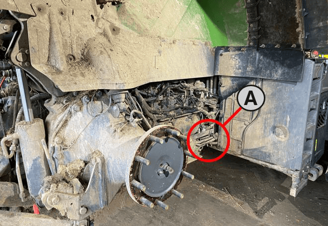
2. Locate the valve/chassis harness connection behind the panel under the rear-right wheel arch, shown as A in the location image.
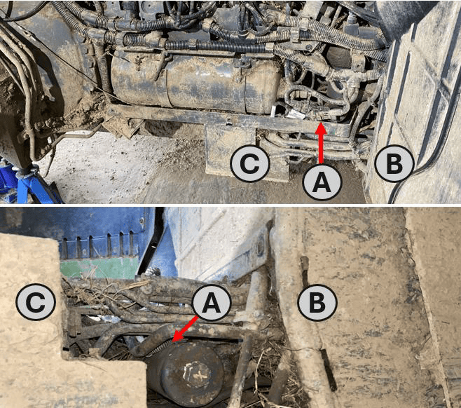
3. Alternatively, it may be accessed from underneath the machine (A) – the bundle can be found amongst the hydraulic lines between the front of the wheel arch (B) and the valve block bracket (C).
(A) - Valve/Tractor Harness bundle
(B) - Front of the Rear Right Wheel Arch
(C) - Valve Bracket, behind Rear Right Wheel
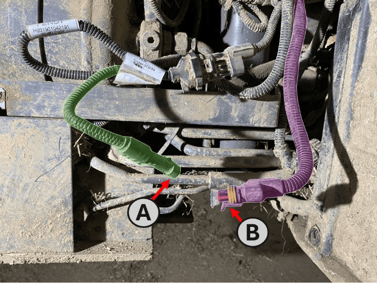
3. Release the connector latch and disconnect the 4-way valve harness receptacle (A) from the tractor chassis harness plug (B).
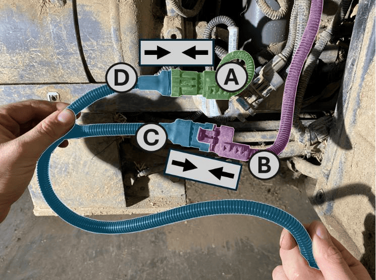
4. Connect the 4-way “Tractor” receptacle (C) on the S/109 harness to the tractor chassis harness plug (B).
5. Connect the 4-way “Valve” plug (D) on the S/109 harness to the valve harness receptacle (A).
(A) – Receptacle on Machine Valve Harness
(B) – Plug on Tractor Chassis Harness
(C) – ‘Tractor’ Receptacle on S/109 Adaptor Harness
(D) – ‘Valve’ Plug on S/109 Adaptor Harness
6. Route the S/109 harness towards the rear of the tractor.
7. Connect the 5-way receptacle on the S/109 harness to the valve-side plug on T3H-V005.
8. Connect the 5-way plug on the S/109 harness to the tractor-side receptacle on T3H-V005.
9. Route T3H-V005 to the COMMAND ECU and connect it to the CAN Interface connector on the T3H-C002 ECU breakout harness.
10. Ensure all connectors are fully seated and latched. Secure the harness clear of the tyre, moving parts, hot surfaces and sharp edges, leaving sufficient slack to avoid strain on the connectors.
11. Refit any components removed for access. Keep COMMAND disarmed and restore the electrical supply.
IMPORTANT: The valve-harness connection and the connection at the rear ISOBUS socket serve different purposes. Connect S/109 to the valve/chassis harness connection identified above.
Where an ISOBUS connection is required for the installation, follow Section 5.4 using the appropriate COMMAND cab or exterior breakout harness.
Tractor Valve Configuration
- Ensure the required tractor SCVs are enabled and unlocked using the tractor’s controls.
- In Level COMMAND, select Fendt SCR/S4/MT as the valve interface.
- Assign the required SCVs to the controlled functions, such as height and cross-slope. These assignments must match the implement’s hydraulic hose connections.
- Prepare the selected SCVs for external control as described below, then verify that each function operates the intended valve in the correct direction.
- Complete valve configuration and calibration before automatic operation.
For detailed configuration and calibration instructions, refer to the Level COMMAND Manual.
Operation Notes
To prepare the selected SCVs for automatic control:
- Ensure the required tractor SCVs are enabled and unlocked.
- Move the COMMAND Arm/Engage switch to the middle ON position to arm COMMAND.
- Move each selected SCV’s tractor control lever into the float position to enable external control of that valve.
- Press the momentary side of the COMMAND Arm/Engage switch to engage automatic control once the system is ready.
NOTE: For SCVs configured for COMMAND control, the lever’s float position enables external hydraulic control. It does not place the valve into hydraulic float.
IMPORTANT: To disengage COMMAND automatic control, press the momentary side of the COMMAND Arm/Engage switch. Move the switch to OFF to disarm COMMAND and disable its hydraulic control commands.
Before handing over the installation, verify manual valve operation and demonstrate how to enable, disengage and resume automatic control.