
7.4 | CNH Pre AFS Connect / PLM Intelligence
Applicable to:
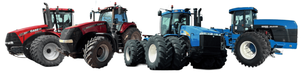
Case IH / New Holland tractors prior to AFS Connect or PLM Intelligence systems.
Connection Method
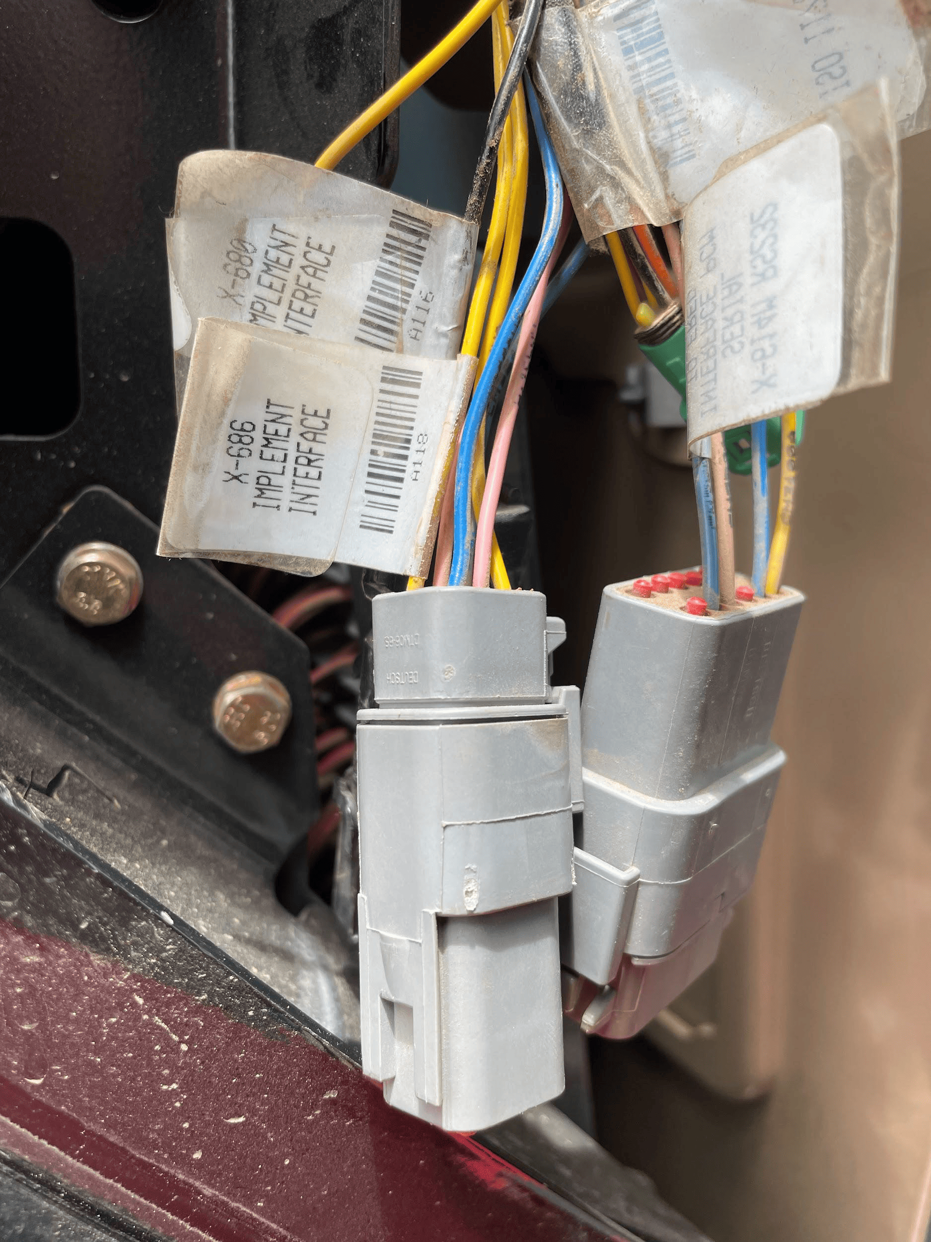 COMMAND can control Case analog input (EHR) valve systems through the use of a T3H-V001 COMMAND Legacy Output Adapter.
Installation Steps
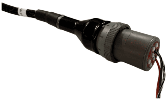
The Case / New Holland tractor connection for analog control signal inputs via the T3H-V001 adapter are generally found in one of three locations depending on tractor mode:
1. Locate the tractor SCV signal input connector:
- Fuse compartment
- Behind driver seat
- Under cab exterior (4WD models)
2. Connect the T3H-V001 adapter to the tractor connection.
3. Connect the T3H-V001 adapter to the T3H-C002 harness.
Tractor Valve Configuration
Select the applicable configuration method:
- New-style instrument cluster
- Old-style instrument cluster
- Tier IV systems
New-style Instrument Cluster
Entering The Configuration Menu
- Locate the corner post instrument cluster in the tractor cab (Pictured right).
- Power up the tractor and press the PROG button on the instrument cluster until “CONFIG MENU” appears.
- Press the “DECR” button until AUX/Hitch/PTO is highlighted and then press the “PROG” button.
- Navigate to “EHR MENU” using the up and down arrow buttons and press the “PROG” button.
Setting Auxiliary Mode
- Use the Up/Down arrow buttons to find “AUX VIEW” and then press the “PROG” button.
- Use the Up/Down arrow buttons until “SCRPR OPTION” appears and then press the “PROG” button.
- Depending on the implement being used, select the correct option using the Up/Down arrow buttons and then press the “PROG” button.
- For single implement height control only - “1 LASER”
- For dual implement height control - “2 LASER”
- For single implement height & cross-slope control - “2 LASER”
Exiting The Configuration Menu
- Press the Up/Down arrow buttons until “AUX EXIT” is shown and then press the “PROG” button.
- Press the Up/Down arrow buttons until “EXIT TMF MENU” is shown and then press the “PROG” button.
- Press the Up/Down arrow buttons until “EXIT” is shown and then press the “PROG” button.
Auto/Manual System Operation
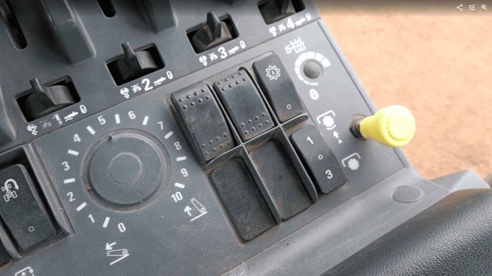
- The tractor will require an Auxiliary (1-3) switch, which is used to toggle between automatic and manual operation for
the two auxiliary inputs. - To toggle between Automatic and Manual operation for either SCV1 or SCV3, press the relevant side of the auxiliary
(1-3) switch.
Old-style Instrument Cluster
Enabling Auxiliary/Remote Valve Control
- Turn on the tractor key switch and within 10 seconds, press and hold the “PROG” button on the instrument cluster for 3 seconds - “INST SET MENU” should appear.
- Press the “INCR” or “DECR” buttons until “AUX SET MENU” is displayed, then press the “PROG” button.
- Press the “INCR” or “DECR” buttons until “AUX SETUP” is displayed, then press the “PROG” button.
- Press the “INCR” or “DECR” buttons to set the required number of “scrapers” between NONE, 1 and 2. In this situation a “scraper” can be considered equivalent to an SCV.
- For single implement height control - select 1 SCRAPER
- For dual implement height control - select 2 SCRAPER
- For single implement height & cross-slope control - select 2 SCRAPER
- Press the “PROG” button to accept the number of scrapers on the display.
Exiting The Configuration Menu
- Press the “INCR” or “DECR” buttons until “AUX EXIT” is displayed, then press the “PROG” button.
- Press the “INCR” or “DECR” buttons until “EXIT SET MENU” is displayed, then press the “PROG” button.
- To complete the calibration process, use the key to turn the ignition off.
CNH Tier IV
Enabling Auxiliary/Remote Valve Control
- Turn on the tractor ignition key switch and within 10 seconds, press and hold the “ENTER” button on the keypad to enter the Config Menu.
- Press the Up or Down arrow keys until “TCU” is displayed and then press “ENTER”.
- Press the Up or Down arrow keys until “EHR MENU” appears and then press “ENTER”.
- Press the Up or Down arrow keys until “EHR SETUP” is displayed and then press “ENTER”.
- “SCRPR NONE” will likely be displayed on the screen. Press the Up or Down arrow button until either “SCRPR 1 LASER” or “SCRPR 2 LASER” is displayed depending on the user’s application and then press “ENTER”.
- For single implement height control only - select 1 LASER
- For dual implement height control - select 2 LASER
- For single implement height & cross-slope control - select 2 LASER
- For single implement height control only - select 1 LASER
- The user can now navigate out of the setup screens or turn the key off - the selected setting will be saved.
Auto-Auxiliary Mode Operation
- The user can toggle between Automatic and Manual operation of the auxiliary outputs using the “1” and “3” buttons on
the console. - The LED on the relevant button will be illuminated when in Automatic operation mode.
- During operation in automatic mode, the upper portion of the programmable display will show the auto state of the auxiliary
outputs. - Automatic control can be temporarily overridden by the operator using the remote hydraulic lever, which will cause the indicator LED on the “1” or “3” console button to flash.
Operation Notes
COMMAND interfaces with the CNH external remotes/valves by sending analog signals to the integrated valve controller, commanding either port A or port B flow of two of the rear tractor SCVs (For AFS Connect models any SCV can be linked to either of the two inputs, whereas older models are limited to SCV1 and SCV3).
To operate the SCVs in automatic control mode, the user first needs to arm one or both of the configured auto SCVs using the 1/3 switch, display or buttons on the armrest .
IMPORTANT: Moving the SCV lever alone will NOT disengage AUTO mode in modern case tractors, so movements based on any current valve signals will continue. Always keep this in mind during operation.
For more information on configuring COMMAND for use with Pre AFS Connect / PLM Intelligence SCVs, refer to the Level COMMAND Manual.