
7.1 | Appearance
ThisThe Appearance page letsallows you adjust the appearance of Level COMMAND. You can control things such as screen brightness, various colors, and what data is shown on the map.
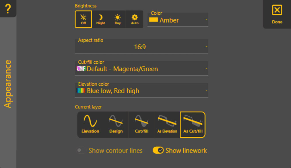
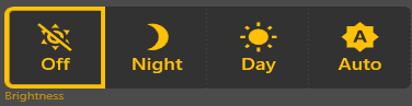
'Brightness' - to easilycustomise control the brightness,how Level COMMAND providesis 4displayed. options.These settings only affect the user interface and map presentation—they do not change how the guidance or automatic control system operates.
Brightness
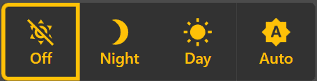
Adjusts the display brightness to suit different lighting conditions.
Off:Off – Level COMMAND does notchangecontrol screen brightness.Night:Night – Reduces brightness for comfortable viewing in low-light conditions.
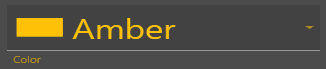
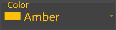 Theme Colour

Aspect Ratio
Optimises the interface layout for your display.
'Color' - select main theme color.
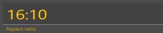
'Aspect ratio' - ChooseSelect the aspect ratio that best option for optimal display onmatches your device(16:9, 16:10).

'Cut/fill color' - Set colors used for Cut/Fill map to Magenta/Green or Red/Green/Blue. (Magenta as cuts/Green as fills, or Red as cuts/Green as neutral/Blue as fills)device:
- 16:9

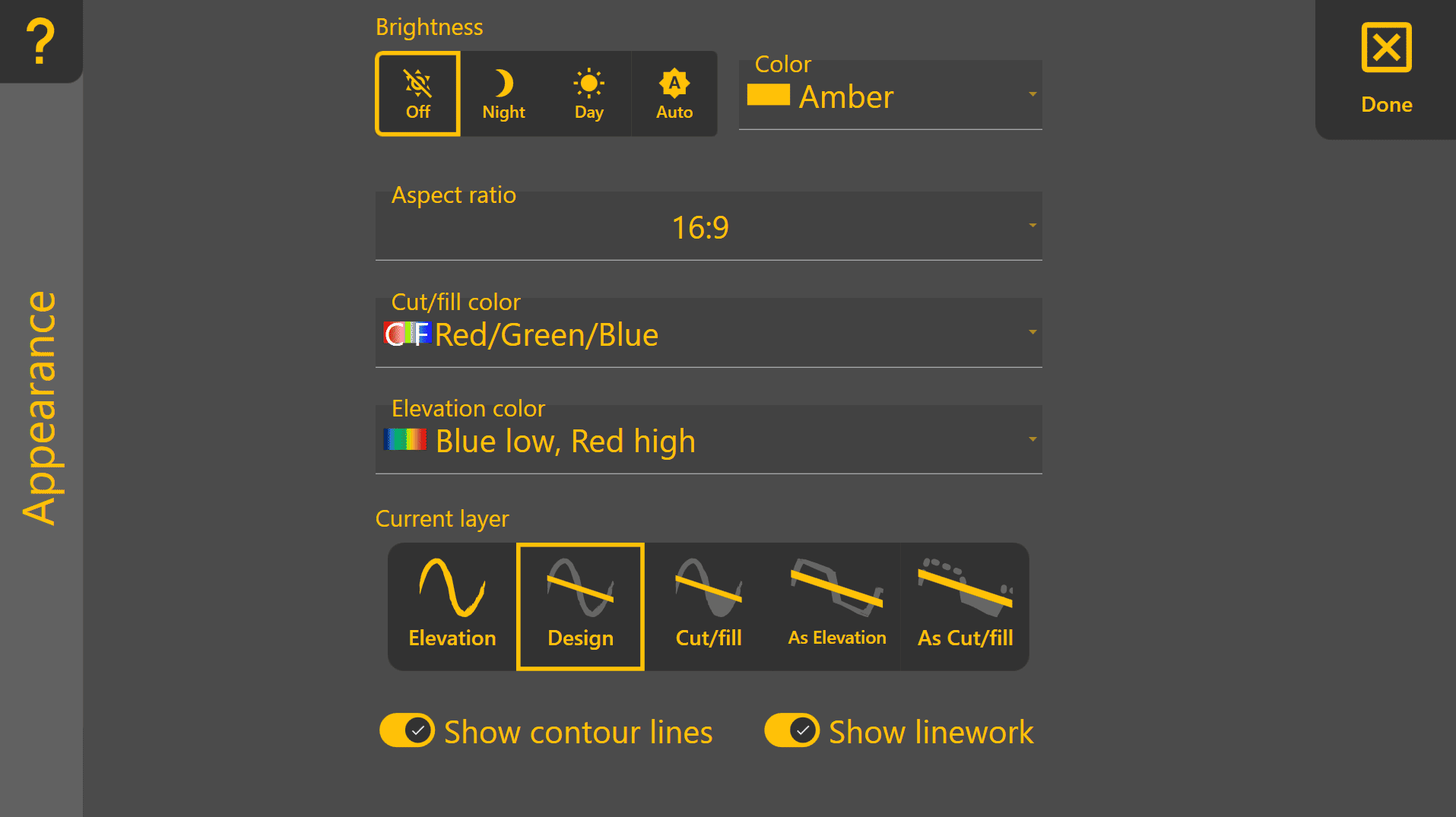
Cut/Fill Colour Scheme
Selects the colours used to display Cut/Fill maps.
Two colour schemes are available:
The Magenta/Magenta / Green color scheme may be easier to viewdistinguish for thosesome users with red/red-green colorcolour blindness.vision Thedeficiency, Red/Green/while Red / Green / Blue color scheme may be preferred by users wantingprovides a clearer delineationvisual indication of “areas already on grade” areas.
grade.

Elevation Colour Scheme
Changes the colour palette used to display elevation maps.
Different colour schemes may improve visibility depending on personal preference or lighting conditions.

Current Map Layer
Selects which project layer is displayed on the map.
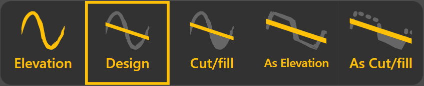
'ElevationAvailable color'layers - Allows you to change which colors represent your highs and lows. This is limited to selecting from a drop down menu.include:
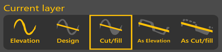
'Current layer' - choose the layer you want to see in the map:
- Elevation
:This–layer showsDisplays the original surveyed ground surfaceprior tobefore anydirtearthworksbeinghavemoved.been carried out. - Design
:This–layer showsDisplays the designto be applied. This is thesurface thatyou are attempting to reach attheendmachineofistheworkingdirt moving process. Has the same color scheme as Elevation.towards. - Cut/
fillFill:– Shows wherethematerialdesign requires dirt tomust beremovedcut oradded,filled relative to the originalelevations.elevationColoring of this layer depends on the current Cut/Fill color (see above). The default is Magenta/Green.surface. - As Elevation
:This–layerDisplaysshowstheelevationmeasuredchangessurface astheyworkoccurprogresses,(the As refers to "As Applied"). It showsproviding areal-timelive representation ofworkcompletedprogress.earthworks.HasContourthe same color scheme as Elevation. Contourslines are notshowndisplayed for thislayer type.layer. - As Cut/Fill
:Shows–where the design requires dirt to be added or removed, relative to As Elevation - i.e.,Displays the remaining cut and filltorequiredcompletebythe design. Coloring of this layer depends oncomparing the current surface with the design surface. Contour lines are not displayed for this layer.
Show Contour Lines
 Enables or disables contour lines on supported map layers.
Contour lines are available for Elevation, Design, and Cut/Fill colorlayers. (see above). ContoursThey are not shown for thisAs layerElevation type.or As Cut/Fill, as these layers update continuously while work is being performed.
Show Linework

'Show contour lines' - Turn contour lines onShows or offhides imported project linework on the map. Contour lines are not shown for As Elevation or As Cut/Fill layers, because they change too much.

'Show linework' - When on,Turning linework isoff displayed. For projects with a lot of linework, this allows you tocan simplify the view.display when working with projects containing a large number of lines or boundaries.