3.6 | Valve Threshold Calibration
Finding
Valve TheThreshold Calibration Menuestablishes
the minimum and maximum output values used by Automatic Control. Access the COMMAND valve calibration page by going to: More > COMMAND Settings > Valve Cals.
Calibration InterfaceProcedure
This page is used to calibrate the valve outputs such that:
Calibration Test Buttons
The interface"+", is"−" shownand "TEST" buttons are used during the calibration process to incrementally increase or reduce a given threshold, which can then be tested using the process described in the screenshot below for the Height function. Each of the up and down direction have their own separate minimum and maximum calibration values.
Once calibrated and performing automatic control, the COMMAND ECU will activate the outputs in the range from minimum to maximum to ensure movement over the whole signal range.
Interface Overview
The Up & Down Sections
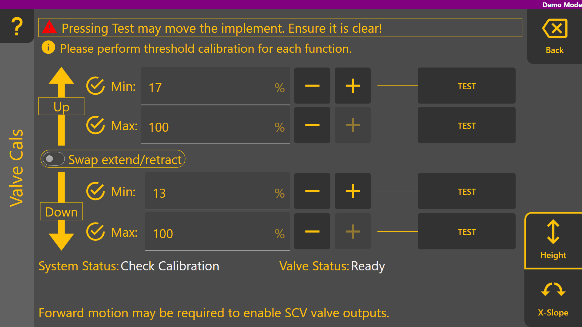
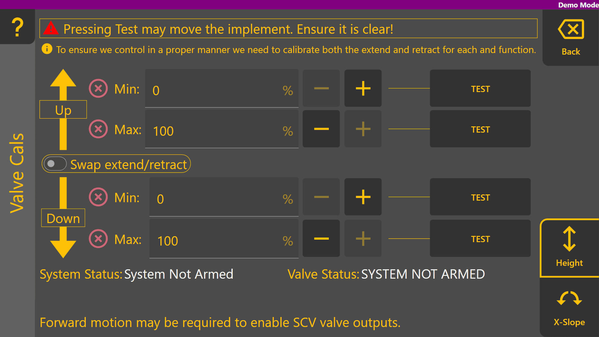
The upper area next to the "Up" arrow shows the the minimum and maximum calibration values used when moving the implement upward.
The area next to the "Down" arrow shows the minimum and maximum calibration values used when moving the implement downward.section.
Calibration Progress Icons
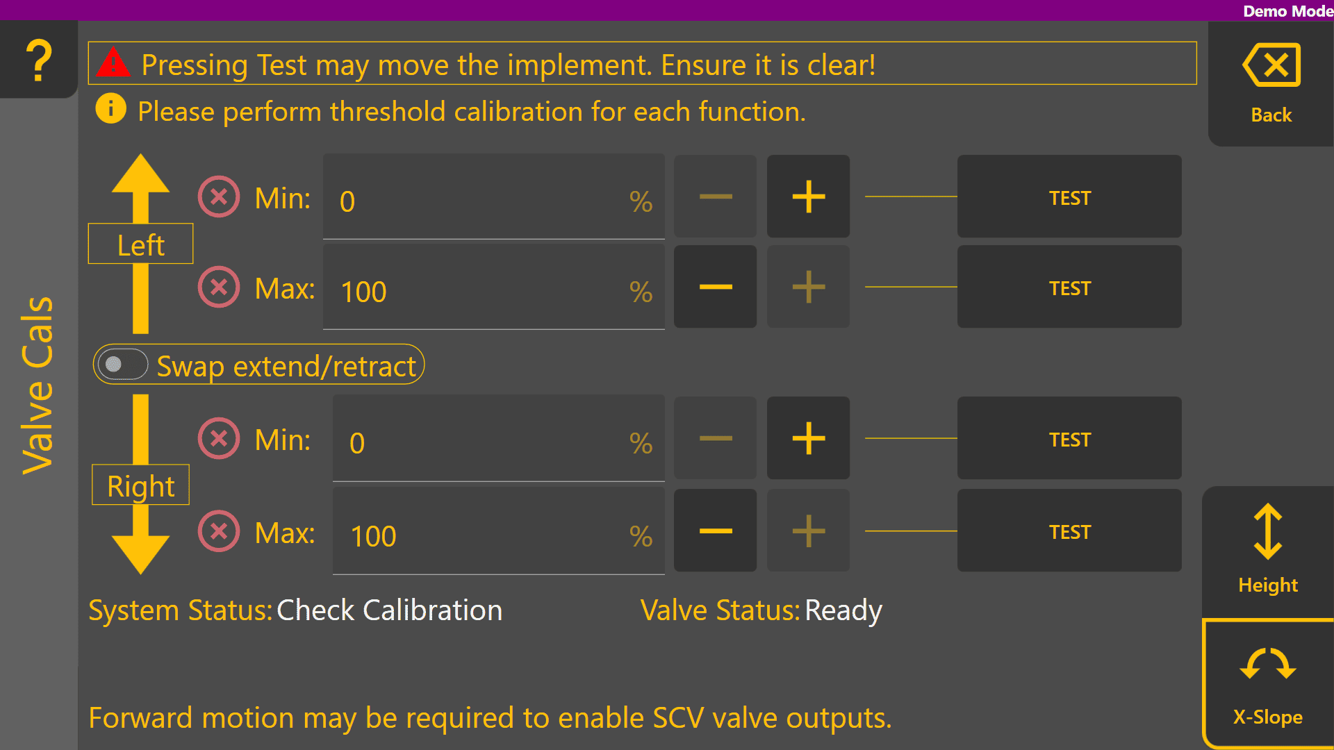
This icon indicates that a value has not been calibrated yet. All minimum and maximum values for all active functions must be calibrated before performing automatic control.
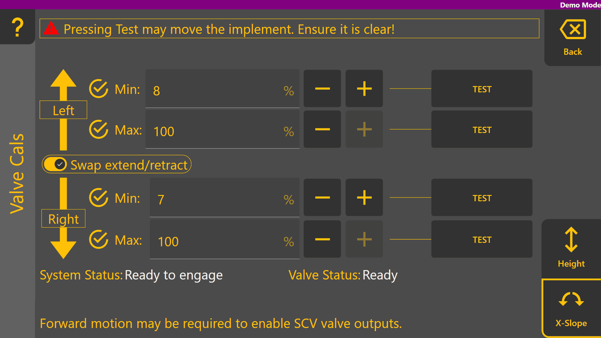
This  icon indicates that a value has been calibrated. Once all min and max values display this icon, the function has been successfully calibrated.
Ticks next to Min or Max values mean that the test button was pressed, but do not indicate a correctly calibrated function.
Validation


Min.movement Threshold
begins By default, the minimum threshold for each direction of each function is 0%. This parameter determines the lowest signal output that the ECU will send to the valve if the height error is greater than X centimeters.
Max. Threshold
By default, the minimum threshold for each direction of each function is 100%. This threshold can be used to reduce the maximum output of the ECU down from 100% (i.e. 100% valve flow), which would have a similar effect to reducing the hydraulic flow output of the hydraulic valve using tractor controls; however, this will generally only affect automatic control speeds, or manual control speeds if an Analog or CANBUS joystick is being used with COMMAND.
For proportional solenoids, the max. % is used to ensure the commanded output signal is no greater than 1800 mA, otherwise overcurrent protection may be triggered by the ECUsmoothly when extendingcommanded.
Swap Extend / Retract
Used to reverse the direction of the function in a similar way to swapping hydraulic hoses around at the back of the tractor.
Calibration Test Buttons
The "+", "−" and "TEST" buttons are used during the calibration process to incrementally increase or reduce a given threshold, which can then be tested using the process described in the next section.
The COMMAND ECU will not request movement of the implement unless the user has pressed one of the test buttons and is holding the engage button.
General Calibration Process
Press the "TEST" button corresponding to the function to be calibrated. A new dialog will open displaying instructing to press the physical "ENGAGE" button to test the hydraulic movement. The function being calibrated and the current valve command value will be displayed.
Ensure the implement is clear of all personnel and objects before pressing the Test button!
Min. Threshold

By default the minimum threshold will be 0%. Increase the min. value by a small amount e.g. 5% and then perform a testing as mentioned above and observe the commanded output milliamps increasing.
The goal is to set Min. % to a value that just barely causes the hydraulic valve to open for a very slow gradual movement. This is sometimes referred to as the valve's "cracking point". We recommended increasing in increments of 5% until gradual movement is seen, then reduce by 1% at a time to find the threshold.
The implement should begin moving consistently when the threshold is exceeded, without
Max.occurs.

Adjust Max. % downward from 100 until the commanded output is roughly 1800mA to provide some padding for changes in solenoid temperature and environmental factors. Continue to reduce this value further if you would like to slow maximum
Proportional Solenoid Calibration Process

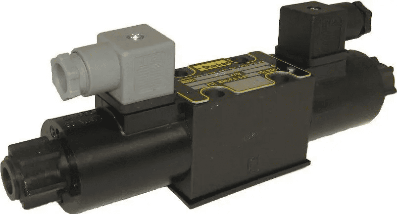
Testing Calibration Values
Press the "TEST" button corresponding to the function to be calibrated. A new dialog will open displaying instructions to press the physical "ENGAGE" button to test the hydraulic movement. The function being calibrated and the current valve command value in milliamps (mA) will be displayed.
Ensure the implement is clear of all personnel and objects before pressing the Test button!
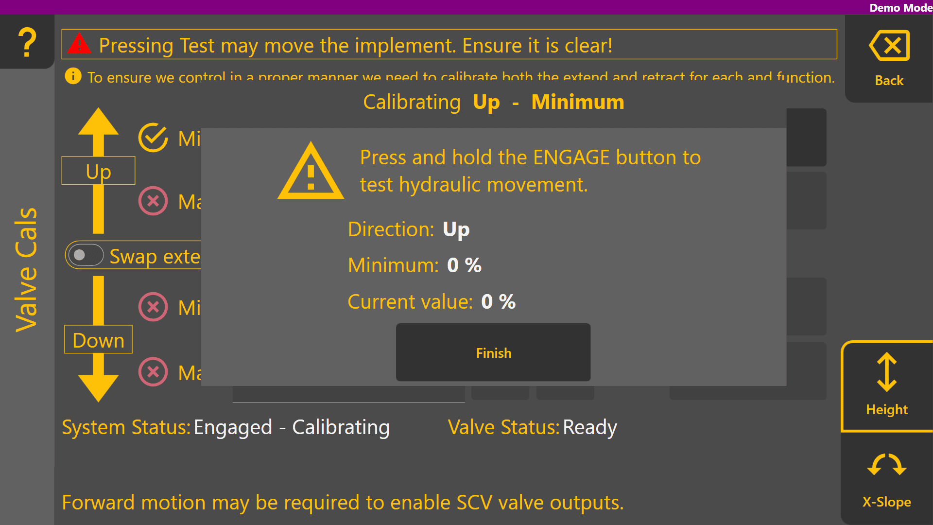
Min. Threshold
By default the minimum threshold will be 0%. Increase the min. value by a small amount e.g. 5% and then perform a testing as mentioned above and observe the commanded output milliamps increasing.
The goal is to set Min. % to a value that just barely causes the hydraulic valve to open for a very slow gradual movement. This is sometimes referred to as the valve's "cracking point". We recommended increasing in increments of 5% until gradual movement is seen, then reduce by 1% at a time to find the threshold.
The implement should begin moving consistently when the threshold is exceeded,available without excessivehydraulic delayinstability.
Max.show Threshold
as
Adjustbefore Max.commissioning %proceeds.