
3.4 | Configuring GNSS
The Inputs/Offsets page is used for selection of input sensors, such as GNSS receivers for height control or Inertial Measurement Units (IMU) for terrain compensation and Tilt / X-slope control.
GNSS Input Configuration
Inputs
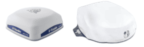
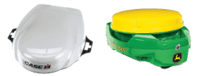
All COMMAND machine profiles have at least one height control function intended for use with a GNSS receiver for vertical position feedback.
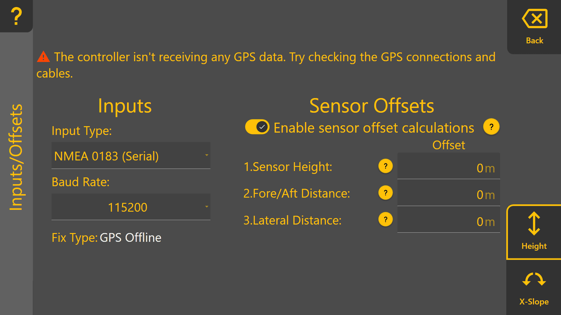
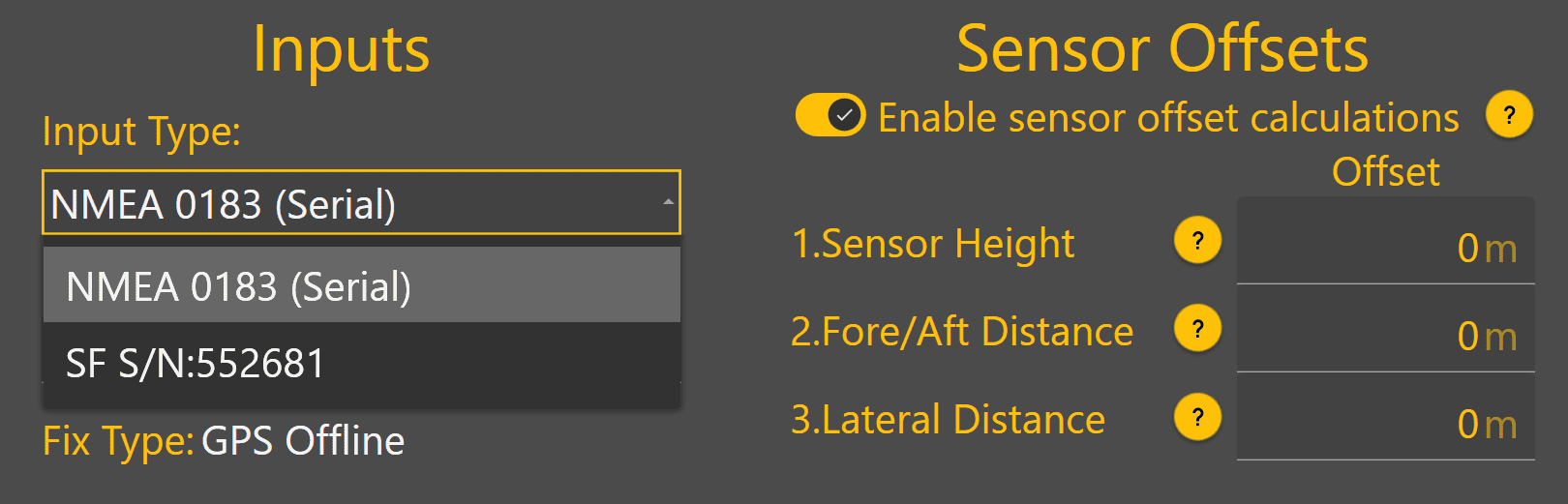
Tap on the dropdown box below Input Type to view the different GNSS input options currently available.
This dropdown will update with any StarFire or NMEA 2000 receivers currently connected, which are then displayed with either "SF" or "N2K" followed by the receiver serial number.
Verify that each function ("Height" if using a single receiver, "Height 1" & "Height 2" if using tandem or dual receivers) has a Fix Type of RTK before proceeding.
Fix Type MUST be RTK for accurate automatic control operation - lower accuracy fix types such as GPS only, Differential or Float RTK are not appropriate for accurate implement position control. Poor GNSS quality will affect machine positioning and automatic control performance.
StarFire Example:
NMEA 2000 Example:
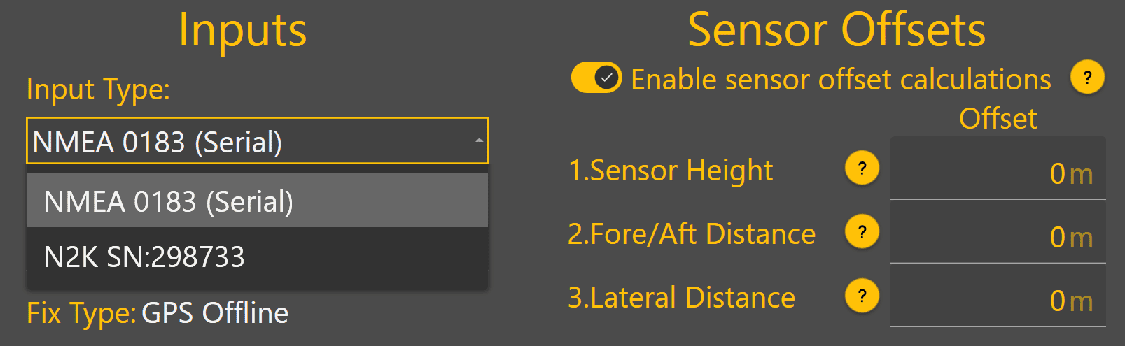
Once the GNSS receiver has been selected, Fix Type should change from GPS Offline to another status to indicate the current GPS quality. If GPS Offline is still shown, the receiver may still be initialising.
Sensor Offsets
If using a GNSS receiver with Level COMMAND that is not capable of IMU-based terrain compensation, sensor offset calculations can be enabled.
Blade Width - Enter the height of the GNSS receiver's measurement point above the cutting edge of the blade.
Positive = Above the cutting edge
Negative = Below the cutting edge
Fore/Aft Distance - Enter the distance forward or backward from the cutting edge of the blade to the GNSS receiver centre point.
Positive = Behind the cutting edge
Negative = In front of the cutting edge
Lateral Distance Enter the distance between the GNSS receiver centre point to the middle of the cutting edge of the blade.
Positive = To the right side of the middle as if standing behind the scraper
Negative = To the left side of the middle as if standing behind the scraper
Sensor Offsets Example:
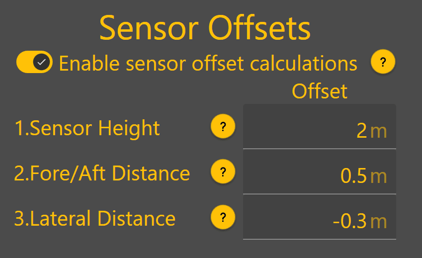 In the example screenshot below, the GNSS receiver has been mounted:
- 2 metres above the blade cutting edge
- 0.5 metres behind the blade (away from the tractor)
- 0.3 metres to the left of the middle of the blade (looking toward the rear of the scraper)
Inputs / Offsets setup is now complete for profiles with only a height control function.
If using Height & X-Slope, Tandem receiver or dual receiver profiles, continue on to set up the second control function's inputs/offsets.
Verifying GNSS Status & Health
GPS Thresholds
GPS Thresholds define the minimum GNSS performance requirements expected by Level COMMAND. These thresholds are used to determine when GNSS warnings should be generated and whether GNSS data quality is suitable for accurate automatic control.
The default values supplied by T3RRA have been selected to provide reliable operation in most environments and should not normally require adjustment. Only modify these values if directed by T3RRA Support or if site-specific conditions require alternative settings.
To access GPS Thresholds:
- Return to the main Level COMMAND screen.
- Press More on the right-hand side of the display.
- Select GPS Thresholds.
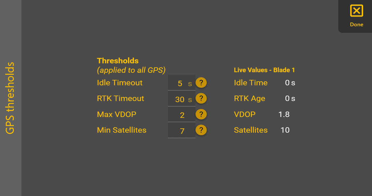
The GPS Thresholds screen allows the following values to be configured:
Idle Timeout
The maximum allowable period of time that GNSS data can stop being received before a warning is generated.
RTK Timeout
The maximum acceptable age of RTK correction data. If corrections exceed this age, GNSS accuracy may no longer be suitable for automatic control.
Max VDOP
The maximum allowable Vertical Dilution of Precision (VDOP).
Lower VDOP values generally indicate better vertical positioning accuracy. A value below 2 is recommended for normal operation.
Min Satellites
The minimum number of satellites required before a warning is generated.
Note that some receivers only report a maximum of 12 satellites even when additional satellites from multiple constellations are being used. This behaviour iscan be normal and depends on the receiver manufacturer.
Live Values
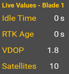
The Live Values panel displays the current GNSS values being compared against the configured thresholds.
During commissioning, verify that:
- GNSS data is updating continuously.
- RTK correction age remains within limits.
- VDOP remains within the configured threshold.
- Satellite count satisfies the minimum requirement.
The Live Values panel provides a convenient method of confirming GNSS health during commissioning. For continuous monitoring during operation, GNSS information can also be displayed using the Widget Interface.
Once GNSS receiver selection, sensor offsets and GPS Threshold verification have been completed, GNSS configuration is complete.
To get back to COMMAND Inputs set up, return to the Level COMMAND main page and press "More" at the right side of the screen > COMMAND Settings > Inputs/Offsets.
To set up a secondary receiver for Height 2, i.e. Tandem implements or implements with dual receiver follow the process above for Height 2 as well.
X-Slope Input Configuration
Some COMMAND machine profiles have a Tilt / X-slope control function intended for use with an IMU for blade tilt / x-slope angle feedback. Tap on the Input Type dropdown box to view currently connected IMU sensors, and select the desired input sensor.
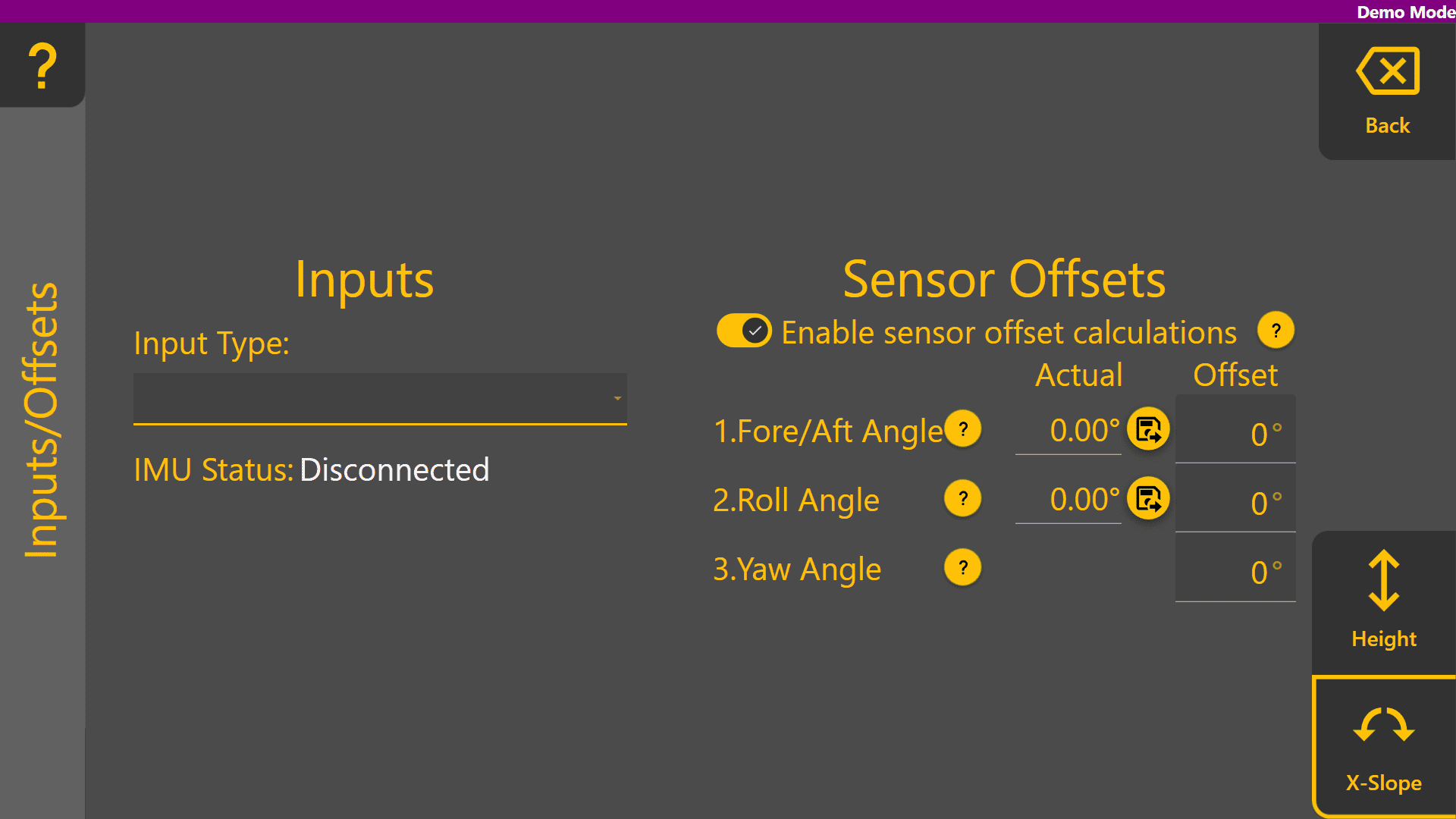
Once selected, IMU Status will change to Connected. Additionally, the "Actual"Actual values for Fore/Aft Angle and Roll Angle underbelow Sensor Offsets will begin updating with the current angle of the selected IMU sensor.
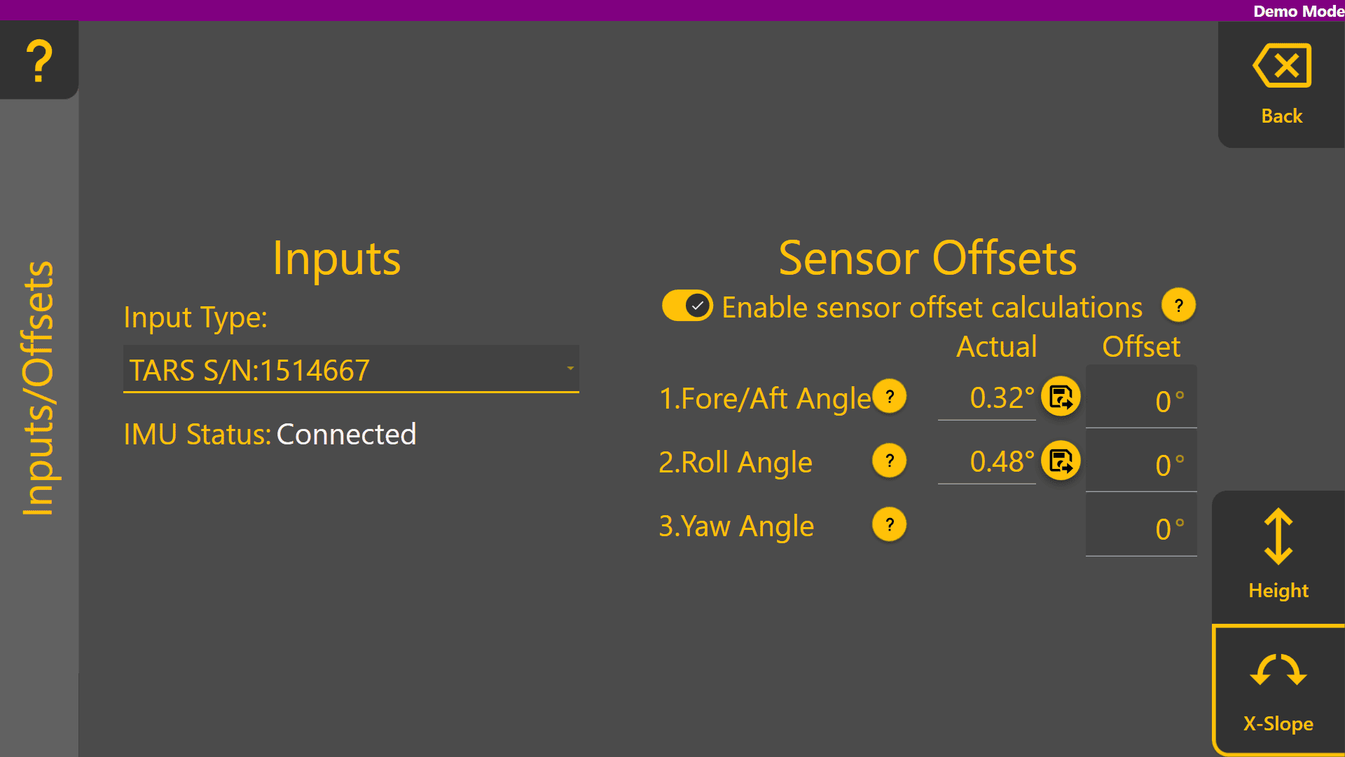
Accounting for IMU Mounting with Offsets
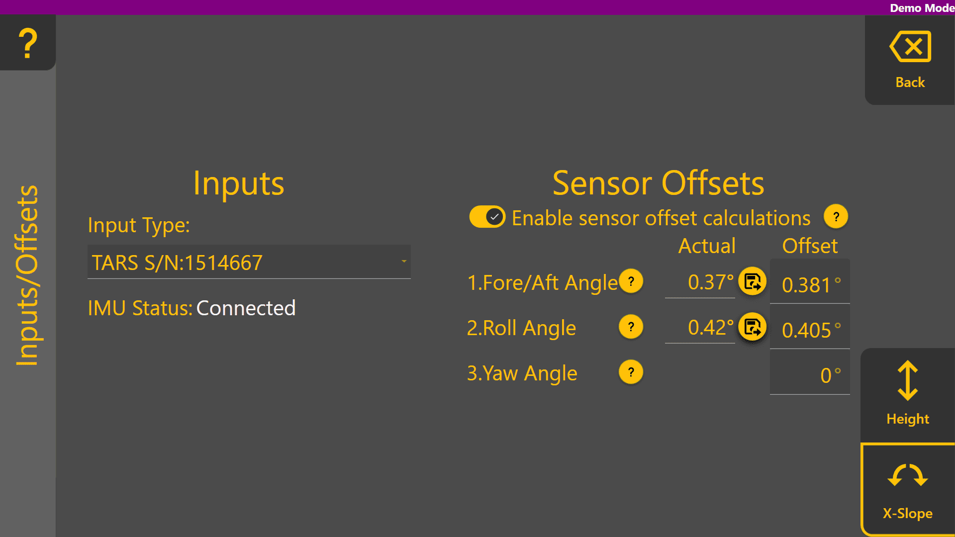
 In cases where the IMU sensor has not been mounted on the blade at a perfect 0 degree pitch
 andand/or roll angle, the save offset buttons can be used to set the Fore/Aft Angle and Roll Angle offsets to the current angle reading. Before doing so, use equipment such as a spirit level, or a known level surface to ensure the blade is completely level. Once done, press the
Offsets are saved in the COMMAND ECU and only need to be changed if the position of the IMU sensor has changed, or if fitting the IMU to a different implement.
Press "Back" to return to the COMMAND Settings Overview and continue on to 3.5 |