
6.3 | Joystick Connection (Optional)
Overview
In most cases the manual control of hydraulic functions are already available (e.g. when using existing tractor SCVs). In some limited cases it may be necessary to add operator control for hydraulic functions, e.g. when using an additional valve module, or using direct PWM operation of hydraulic valves from the COMMAND ECU. In these situations, two options are available: An analog joystick, or a J1939 CANBUS joystick.
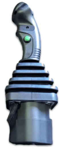
If using a compatible analog or J1939 CANBUS joystick, this can be connected to the T3H-C002 directly or via a joystick extension harness.
- Ensure the joystick is fitted with an 8-way Deutsch DT plug (DT06-8S).
- Mount the joystick in an appropriate location in-cab according to manufacturer mounting instructions.
- Connect the plug to the connector labelled “Joystick” on the T3H-C002 harness.
- Verify correct pin alignment before connecting.
See below for the pin positions and connector information noting that this is the receptacle on the T3H-C002 ECU breakout harness.
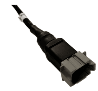
Mating joystick connector parts:
- Connector: DT06-8S / DT06-8SA
- Contacts: 1062-16-0122 or AT62-16-0122
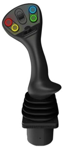
Analog JoysticksJoystick Installation
Analog joysticks from brands such as APEM, Parker, Suregrip Controls or Danfoss can be connected to the system and used to manually control one or both available functions, e.g. Height and X-Slope.
Analog Joystick Specification Requirements
- Expected output range: 1.0 - 4.0V
- Expected resting voltage: 2.5V
Analog Joystick Connection
The T3H-C002 ECU Breakout Harness has an 8-pin joystick connection available that can be used to provide switched 12V power and access to the analog joystick signal inputs. Generally, Joystick Axis 1 and Joystick Axis 2 should be connected to the Y and X axis of the joystick respectively.
1. Connect joystick to the 8-pin joystick connector on the T3H-C002 harness.
2. Connect power to Switched 12V and GND.
3. Connect signal outputs to joystick axis inputs.
4. Verify voltage range is within 1.0–4.0V.
NOTE: The Joystick Axis 3 signal is currently not in use - COMMAND is currently capable of controlling 2 functions for manual control.
Analog Voltage Signal Requirements
The joystick output voltage must be centred at 2.5V when not being manipulated, and should lower in voltage to a minimum of 1V in one direction, and to a maximum of 4V when moved in the opposite direction.
IMPORTANT: 0-5V Output range joysticks cannot be used with COMMAND, as input voltages of 0V and 5V are assumed to be a short circuit to ground or 5V respectively.
J1939 / CANBUS JoysticksJoystick Installation
A ruggedised multifunction J1939 CANBUS joystick with suitable output messages can be connected to the joystick connection on COMMAND harnessing to provide manual operator control of the scraper.
A J1939 joystick such as the APEM HF Series J1939 joysticks can be connected to the system and used to manually control the two available functions, e.g. Height and X-Slope.
Interface Parameters
- Baud rate: 250 kbps
- Transmission repetition rate: Recommended 10 hz or higher
Connection
The joystick connector on COMMAND harnessing can provide a 12V DC supply for the joystick, and then receive joystick position messages back via CANBUS. The COMMAND ECU has been programmed with J1939/ISO basic joystick message types to provide selection between fore/aft, left/right and twist axes for each of COMMAND's control functions. See below for pinout information.
1. Connect joystick power to Switched 12V and GND.
2. Connect CAN HI and CAN LO to ISOBUS HI and LO.
3. Verify communication at 250 kbps.
4. Confirm joystick inputs are detected in Level COMMAND.
Expected Message Protocol
Message 1 - BJM1 - PGN 0xFDD6
Primary X-axis or Y-axis can be assigned to COMMAND function 1 or function 2.
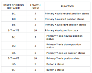
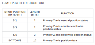
Message 2 - EJM1 - PGN 0xFDD7
Primary Z-axis or Y-axis can be assigned to COMMAND function 1 or function 2.
For more assistance in setting the selected joystick type and joystick axes within Level COMMAND, please refer to the Level COMMAND manual.