Create Plane surfaces
Plane Project allows users to create simple surfaces without surveying the entire area.
The Level COMMAND feature supports the creation of up to four plane surfaces.surfaces that can quickly be swapped between. These 4 surfaces can be used to define different aspects of a project for example, each plane could be used to define different pads.
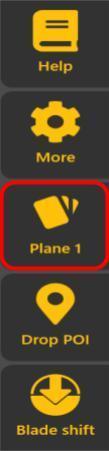
Once the new plane project is created, the Plane button will appear on the main page.
Steps to set upSelect/Define a plane
surface
surfaces
Start by clicking the "Planes" button on the right sidebar.
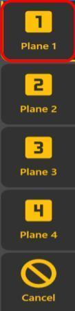
1To edit an existing plane tap on it again after already having it selected. (ie, click Plane from the main view, click "Plane 1", then it will swap to "Plane 1". Click "Plane" from the main view again and then click "Plane 1" buttonagain. toNow openyou will see the edit screen.)
To define a new plane list.click on any unused slot (Byit default,will be labeled as "PlaneCreate") 1"and isthen selected.)you will see the edit screen


2. Select the plane surface you want to use.
Plane Editor
3.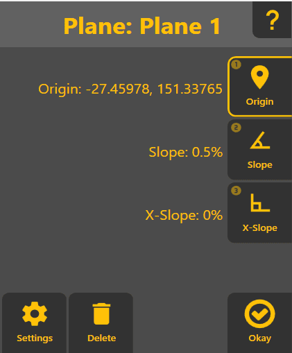
On the right you can set the Origin Point(aka usinganchor point), the Slope (primary slope and direction) and X-Slope (the slope at right angles to the primary slope).
Settings lets one change the size of the followinggenerated methods:plane, and also set the plane name.
GPSDelete: Useswill delete the active plane, allowing it's slot to be reused.
Ok will close the editor and allow the plane to be controlled to.
In the top right, a Help button will allow you to quickly reference this help document.
Plane Editor: Origin
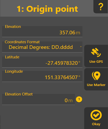
This allows one to define where the plane's height and where it is pivoting around when setting Slope and X-Slope.
Use GPS: Will take the current GPSposition location.
Marker: Opensof the markerimplement listand foruse selecting a markerthat as the origin.
EditUse Marker: Will allow you to select a marker to use as the origin
Elevation/Latitude/Longitude: Defines the position of the origin. Can be set via GPS or a marker by clicking on "Use GPS" or "Use Marker". The "Coordinates Format" will allow one to specify the latitude/longitude in various formats - ie it's only a visual change.
Elevation Offset: OpensAllows the locationshifting of the plane up or down relative to the GPS position. Separate from Elevation so it can be clearly adjusted as required - changing the main elevation value would do the same thing but make it harder to reconstruct what was done when reviewing the defined plane after the fact.
Okay: Will take you back out to the Plane editor
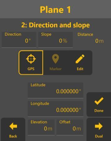
Plane manualEditor: input.
Slope
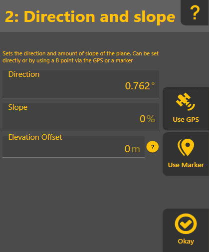
4.Direction: DecideWhich directionway andthe slope value will affect the plane.
Slope: How steep the grade of the plane will be (in percentage notation - ie 100 x rise / run )
Elevation Offset: Only shown after using GPS or a marker. Allows the changing of the slope by GPS,a markerfixed orelevation. EditIe (manual input).Ifif you wantknow you need to usecut a10cm dual slope, click the "Dual" button after setting both direction and slope.Otherwise, click "Done".
5. (Optional) Set a Dual Slope using GPS, Marker, or Edit manually.Click "Done" when you're satisfied withat the current result.location, enter 10cm here and it will calculate the appropriate slope.
Use GPS: Will take the current position of the implement, and calculate the heading/slope between that and the 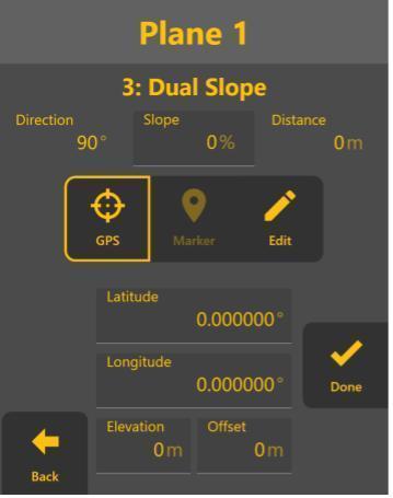
Use Marker: Will allow the selection of a marker, and calculate the heading/slope between that and the Origin. These values can then be edited afterwards if the values aren't quite as desired.
Okay: Will take you back out to the Plane editor
Plane Editor: X-Slope
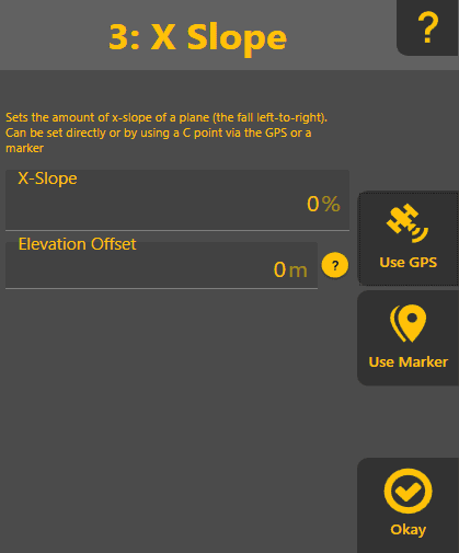
The x-slope is the slope at right angles/90° to the primary slope. It shares a similar behavior to the e primary slope UI except doesn't allow the specification of direction
Slope: How steep the grade of the plane will be (in percentage notation - ie 100 x rise / run )
Elevation Offset: Only shown after using GPS or a marker. Allows the changing of the slope by a fixed elevation. Ie if you know you need to cut 10cm at the current location, enter 10cm here and it will calculate the appropriate slope.
Use GPS: Will take the current position of the implement, and calculate the heading/slope between that and the Origin. These values can then be edited afterwards if the values aren't quite as desired.
Use Marker: Will allow the selection of a marker, and calculate the heading/slope between that and the Origin. These values can then be edited afterwards if the values aren't quite as desired.
Okay: Will take you back out to the Plane editor