
6.4 | Blade Shift & Target Adjustment
Blade Shift allows the operator to temporarily adjust the target position during grading without modifying the underlying design surface.
ThisBlade providesShift achanges quickthe methodcurrent ofTarget—not makingthe smallDesign. gradingRemove adjustmentsthe applied shift at any time to suitreturn changingAutomatic siteControl conditions while preservingto the original projectdesign design.surface. UnlikeIf Zero,large whichBlade alignsShift values become necessary, verify the project toalignment theand realconsider world,performing Blade ShiftZero simply offsets the current target position. The design surface itself is never changed.instead.
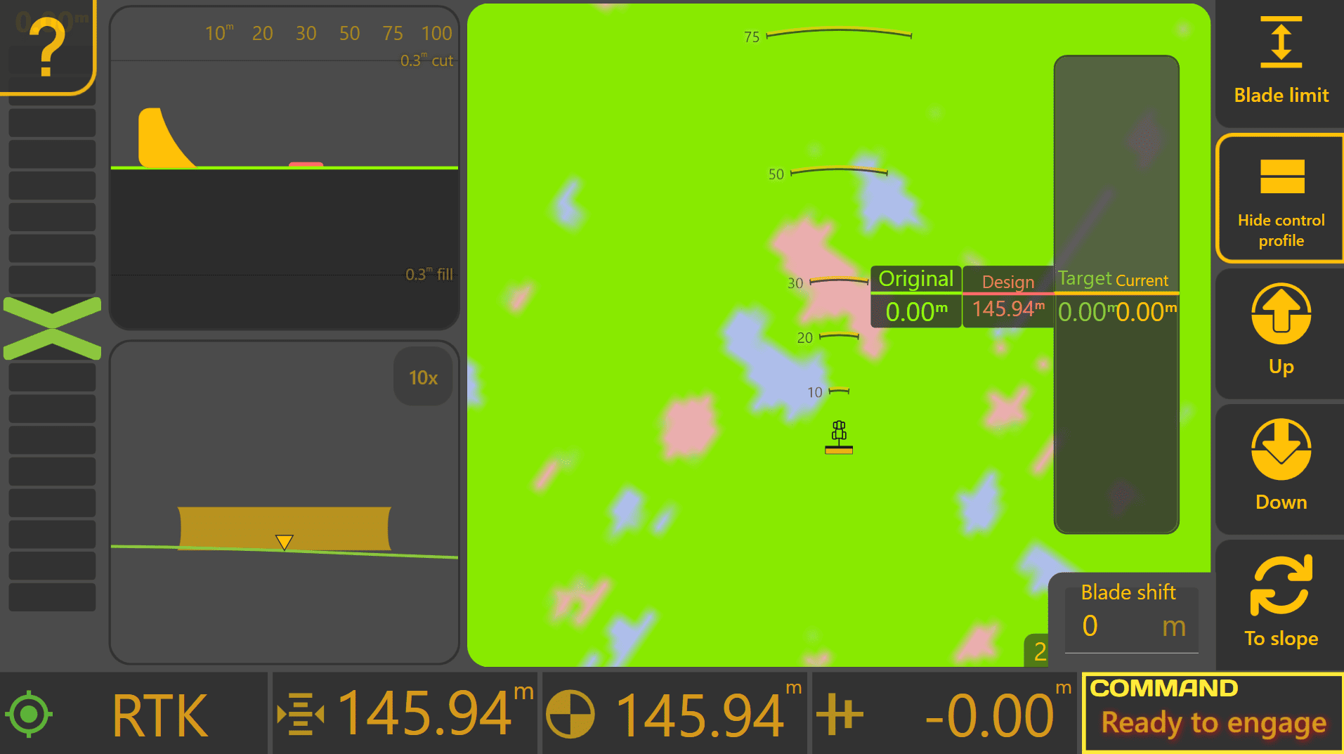
To access the Blade Shift controls from the Apply View:
Press Blade Shift.
Understanding the Control Profile
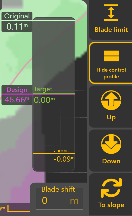
The Control Profile provides a live cross-sectional view of the current grading state. It allows the operator to see how the original ground, design surface, target position and current implement position relate to one another during Automatic Control.
The Control Profile displays four key references:
Original
The original surveyed ground surface before grading began, shown relative to the design surface.
Design
The intended finished surface. This remains fixed throughout the project and represents the final grading objective.
Target
The position currently being tracked by Automatic Control.
Normally, the Target matches the Design. However, Blade Shift or Dynamic Cut/Fill Limiting may temporarily adjust the Target while leaving the Design unchanged.
Current
The current implement position relative to the Design.
As Automatic Control operates, the Current position should progressively move towards the Target.
 Blade Shift
The Up and Down buttons temporarily raise or lower the Target by the configured Blade Shift Increment.
Multiple adjustments can be applied as required, and the current Blade Shift value is displayed within the Blade Shift window. Selecting the displayed value allows a specific offset to be entered directly.
Because Blade Shift modifies only the Target position, the original Design remains unchanged and can be returned to at any time by removing the applied shift.
Dynamic Cut & Fill Limiting

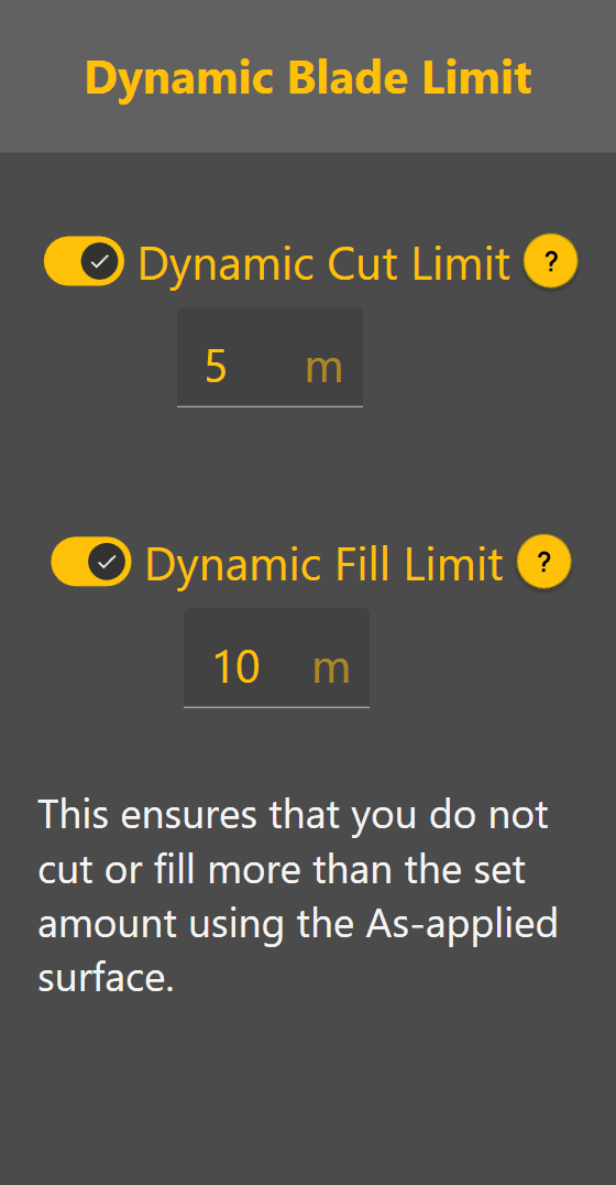 Dynamic Cut and Fill Limiting temporarily restrict how much material Automatic Control attempts to remove or place during a single pass.
Rather than immediately targeting the finished Design, Level COMMAND calculates a temporary Target Position that respects the configured Cut or Fill Limit.
This can be useful when:
- Removing material in multiple controlled passes.
- Reducing machine load.
- Preventing excessive cutting or filling in a single pass.
- Minimising operator intervention on difficult ground.
As each pass is completed, the Target Position progressively moves towards the final Design until the required surface is achieved.
 Manual X-Slope Adjustment


Machines equipped with Height & X-Slope control can temporarily adjust the target cross-slope.
Select To Slope to switch from Blade Shift controls to X-Slope controls.
When X-Slope Auto is enabled, Level COMMAND automatically follows the design cross-slope. When Auto is disabled, the operator may manually adjust the target cross-slope using the Left and Right controls or enter a specific value directly.
Select To Shift to return to the Blade Shift controls.
Blade Shift Increment
The amount applied by each press of the Up or Down buttons is determined by the configured Blade Shift Increment. Likewise, manual X-Slope adjustments use the configured X-Slope Shift Increment.
To change the Blade Shift Increment, from the Apply View press More > Blade Shift Settings.
Smaller increments provide finer control, while larger increments allow quicker adjustments during grading.
Typical Blade Shift Increment values are:
- 0.01–0.02 m
- 0.4–0.8 in
- 0.03–0.06 ft
These values provide a good balance between adjustment precision and operating efficiency for most grading applications.
Operator Tip: Use Blade Shift to make temporary grading adjustments as conditions change throughout the day. If large Blade Shift values become necessary to maintain the desired grade, verify the project alignment and consider performing Zero again rather than continuing to increase the applied offset.
Continue to 6.5 | Position Quality & GNSS Validation to understand how Level COMMAND validates positioning information before Automatic Control is allowed to operate.