
6.4 | Blade Shift & Target Adjustment
TheBlade bladeShift shiftallows buttonsthe allow youoperator to manuallytemporarily shiftadjust the heighttarget position during grading without modifying the underlying design surface.
This provides a quick method of themaking blade;small up,grading down,adjustments orto rotatesuit itchanging (forsite cross-slopeconditions control).while You can also limitpreserving the depthoriginal ofproject cutdesign. andUnlike fillZero, withwhich blade limits. To use it, clickaligns the 'project to the real world, Blade shiftShift' button.simply offsets the current target position. The design surface itself is never changed.

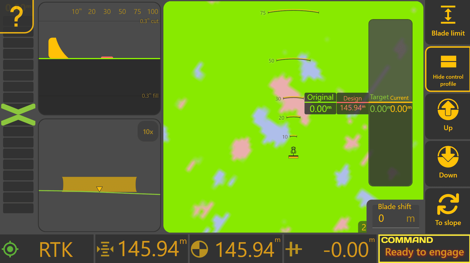
Breakdown ofaccess the Blade Shift UIcontrols from the Apply View:
Press Blade Shift.
Understanding the Control Profile
Blade view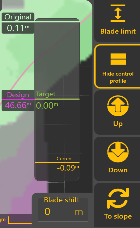
The BladeControl limit:Profile Allowsprovides youa live cross-sectional view of the current grading state. It allows the operator to setsee limits onhow the bladeoriginal relativeground, design surface, target position and current implement position relate to theone Asanother Appliedduring surface.Automatic Control.
The Control Profile displays four key references:
Show/Hide control profile:Original Shows or hides the "control profile" display (see right).
ControlThe profile:original Ansurveyed overlaidground displaysurface thatbefore showsgrading youbegan, all the stats about what is happening with the control loop. For example, the position of your bladeshown relative to the design surface.
Design
The theintended what the goal is to hit - the designfinished surface. This isremains labelledfixed withthroughout itsthe absoluteproject elevation.
Target
The whatposition currently being tracked by Automatic Control.
Normally, the ECUTarget is currently targeting. For example, ifmatches the bladeDesign. hasHowever, beenBlade shiftedShift byor -3cmDynamic (aboutCut/Fill 1Limiting inch),may ittemporarily will be 3cm below design. It will also displayadjust the effectTarget ofwhile aleaving blade limit when applicable. If there was no shifts or limits present then it would matchthe Design asunchanged.
Current
The current heightimplement of the blade/implement,position relative to the designDesign.
As Automatic Control operates, the Current position should progressively move towards the Target.
 Blade Shift
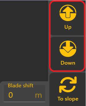
The Up and Down buttons temporarily raise or lower the Target by the configured Blade Shift Increment.
Multiple adjustments can be applied as required, and the current Blade Shift value is displayed within the Blade Shift window. Selecting the displayed value allows a specific offset to be entered directly.
Because Blade Shift modifies only the Target position, the original Design remains unchanged and can be returned to at any time by removing the applied shift.
Dynamic Cut & Fill Limiting

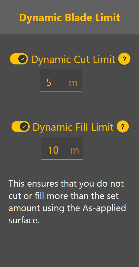 Dynamic Cut and Fill Limiting temporarily restrict how much material Automatic Control attempts to remove or place during a single pass.
Rather than immediately targeting the finished Design, Level COMMAND calculates a temporary Target Position that respects the configured Cut or Fill Limit.
This can be useful when:
Up/Down:As Willeach adjustpass youris targeted blade height bycompleted, the bladeTarget shiftPosition increment.progressively moves towards the final Design until the required surface is achieved.
Blade shift:
 Manual
 text-boxX-Slope showsAdjustment

ToMachines slope:equipped Thiswith willHeight let& you change from nudging up/down to editing cross slope.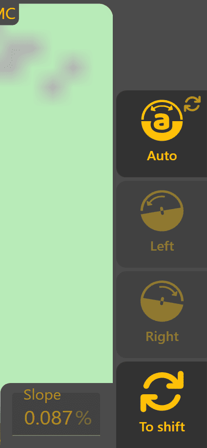
Only present if you have a cross slope capable setup.
X-Slope view
Auto: Allows one to turn on/off the automatic control of cross-slope (X‑Slope). If in "auto" (see screenshot) the cross-slope will be controlled by the design surface's slope.
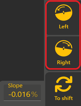
Left/Right: Will adjust your targeted blade height by the X-Slope shift increment. Will be disabled in Auto.
Slope: This text-box shows the current target X‑Slope. Tapping on it will allow exact entry of a desired slope. Is disabled in Auto.
To Shift: This switches back from editing cross-slope to editing blade shift.
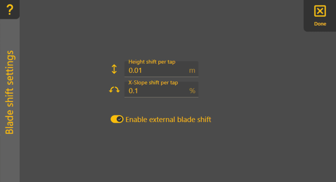
This is where you can change how blade shifting behaves. You can set the amount changed with each tap of the blade shift buttons. This affects how quickly you can use blade shift totemporarily adjust the target position. cross-slope.
Note:Select 'To Slope to switch from Blade Shift controls to X-Slope shiftcontrols.
When tapX-Slope Auto' won'tis beenabled, presentLevel ifCOMMAND yourautomatically setupfollows doesn'tthe havedesign cross-slope. When Auto is disabled, the operator may manually adjust the target cross-slope available.using the Left and Right controls or enter a specific value directly.
Blade Shift Increment
The amount applied by each tappress of the up/downUp adjustmentor Down buttons causesis determined by the bladeconfigured shiftBlade toShift change.Increment. RecommendedLikewise, distancemanual forX-Slope adjustments use the bladeconfigured shiftX-Slope incrementShift wouldIncrement.
To 0.03change -the 0.06Blade feetShift (0.4Increment, -from 0.8the inches,Apply orView 0.01mpress -More 0.02m).> Blade Shift Settings.
Smaller increments provide finer control, while larger increments allow quicker adjustments during grading.
Typical Blade Shift Increment values are:
These values provide a good balance between adjustment precision and operating efficiency for most grading applications.
Operator Tip: Use Blade Shift to make temporary grading adjustments as conditions change throughout the day. If large Blade Shift values become necessary to maintain the desired grade, verify the project alignment and consider performing Zero again rather than continuing to increase the applied offset.
'X-Slope shift increment' - set the amount each tap of the manual left/right cross slope adjustment buttons causes the cross slopeContinue to change.6.5 Uses| percentagesPosition (notQuality degrees).
'Enable external blade shiftValidation' - With this you can also enable or disable the external blade shift feature. You shouldn't need to disableunderstand ithow unlessLevel theCOMMAND buttonsvalidates arepositioning malfunctioninginformation andbefore sendingAutomatic manyControl bladeis shiftallowed commands.to operate.