
6.3 | Blade Control Modes
Blade Control Modes determine how Level COMMAND interprets the design surface beneath the blade when calculating the required target position.
Different grading situations benefit from different control strategies. Some modes prioritise accurately following the design, while others minimise overcutting or improve performance around sudden changes in terrain.
Selecting the appropriate Blade Control Mode can improve grading efficiency, reduce rework and produce a more consistent finished surface.
The available Blade Control Modes are described below.
Classic
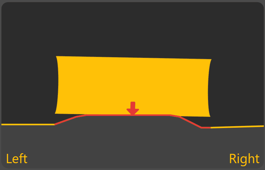
Classic uses the design elevation directly beneath the centre of the blade as the target position.
For Height & X-Slope applications, cross-slope is calculated using the design elevations beneath the left and right edges of the blade.
This mode follows the design exactly but may overcut when crossing sudden changes in terrain, such as ditch centres or sharp breaklines.
Typical applications include:
- General grading on smooth surfaces.
- Areas with gradual changes in terrain.
Average
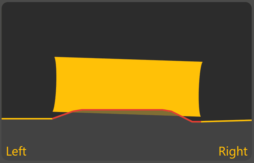
Average determines the overall trend of the design surface beneath the blade and positions the blade to follow that average profile.
This produces smooth grading performance across broad, continuous surfaces and reduces sensitivity to small variations in the design.
Typical applications include:
- Broadacre landforming.
- Large paddocks.
- Surfaces with gradual, continuous grades.
Average On Top

Average On Top uses the same averaging method as Average, but positions the blade to avoid cutting below the design surface.
This helps prevent overcutting while maintaining smooth grading performance.
Typical applications include:
- Finishing passes.
- Projects where preserving the design surface is more important than maximising material removal.
- Areas where overcutting must be avoided.
Snap Fit

Snap Fit determines the blade position that best matches the design while avoiding unnecessary overcutting.
When crossing abrupt changes in terrain, such as breaklines or drain batters, the blade rapidly transitions between adjacent design surfaces rather than averaging across them.
This allows sharp design features to be maintained while reducing unnecessary passes.
Typical applications include:
- Drain construction.
- Batters.
- Breaklines.
- Designs containing abrupt changes in grade.
Single Point
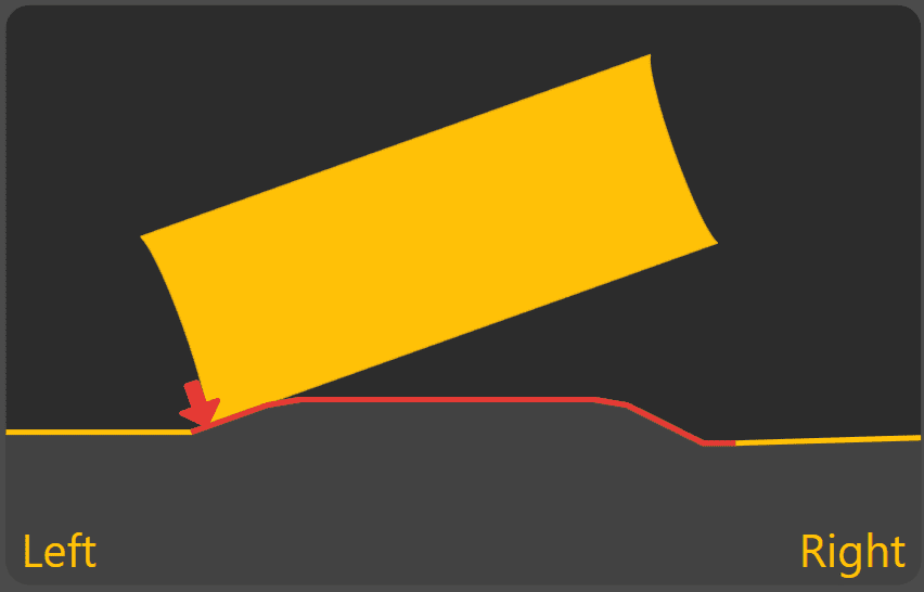
Single Point controls a single selected point on the blade rather than considering the full blade width.
The selected control point is maintained on the design surface even though other parts of the blade may be above or below the design.
This mode is particularly useful for constructing features where one point of the blade must accurately follow the design.
Typical applications include:
- V-drains.
- Channels.
- Working against existing edges.
- Precision grading using one side of the blade.
When Single Point is active, the Swap Ctrl button is displayed in the Back View. This allows the active control point to be quickly swapped between the left and right sides of the blade when changing travel direction.
Choosing a Blade Control Mode
No single Blade Control Mode is ideal for every grading task.
Broad, continuous grading generally benefits from Average or Average On Top, while projects containing drains, batters or sharp terrain changes are often better suited to Snap Fit or Single Point.
Operators should select the mode that best matches the design being constructed and the type of grading being performed.
Continue to 6.4 | Blade Shift & Material Control to learn how the target position can be temporarily adjusted during grading without modifying the underlying design.