
5.3 | Widget Customisation
The widgets along the bottom of the Apply View provide quick access to important machine, GNSS and grading information while operating Level COMMAND.
Almost every widget can be replaced with another value, allowing the display to be customised to suit different operators, machine configurations or grading tasks.
The COMMAND Status widget at the far right of the Apply View is fixed and cannot be changed.
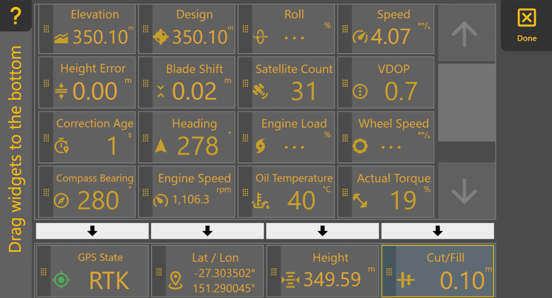
Opening Widget Settings
To customise the displayed widgets:
- Press and hold any configurable widget along the bottom of the Apply View.
- The Widget Settings page will open.
The upper section displays all available widgets, while the lower section shows the widgets currently displayed on the Apply View.
Changing Displayed Widgets
Widgets can be replaced using either of the following methods.
Drag and Drop
Press and hold any available widget, then drag it onto one of the widget positions along the bottom of the screen.
When released, the selected widget replaces the existing widget.
Arrow Selection
Alternatively:
- Select the desired widget from the upper list.
- Press the arrow above the widget position you wish to replace.
This method can be easier when operating with gloves or on smaller displays.
Reordering Widgets
Widgets may also be rearranged by dragging them between positions along the bottom row.
When finished, press Done to return to the Apply View.
Changing Measurement Units
Many widgets display measurements using configurable units.
To change measurement units:
More → Units
The available units depend on the information being displayed.
Available Widgets
| Widget | Description |
|---|---|
| Elevation | Current surveyed ground elevation at the implement location. |
| Design | Design elevation at the current location. |
| Height | Current implement height. |
| Cut/Fill | Amount of cut or fill required at the current location. |
| Height Error | Difference between the current implement height and the target height. Persistent error may indicate incorrect valve calibration or that the implement cannot physically reach the target. |
| Blade Shift | Displays the current Blade Shift offset applied to the target surface. This widget displays the active offset only; Blade Shift is adjusted using the Blade Shift control on the Apply View. |
| Speed | Current machine speed. |
| Heading | Current direction of travel relative to north. |
| Latitude / Longitude | Current GNSS position. |
| Roll (X-Slope) | Current implement roll angle. |
| Target Roll | Target roll angle defined by the design surface. |
| Roll Error | Difference between the measured roll angle and the target roll angle. Useful when monitoring X-Slope performance. |
| GNSS Status | Current GNSS positioning quality. RTK provides the highest positioning accuracy. |
| Satellite Count | Number of satellites currently being tracked. Some receivers may report fewer satellites than are actually contributing to the position solution. |
| VDOP | Vertical Dilution of Precision. Lower values generally indicate better vertical positioning accuracy. |
| Correction Age | Time since the last RTK correction was received. Lower values indicate a healthier correction link. |
| Actual Torque* | Engine torque currently being produced. |
| Demanded Torque* | Engine torque currently being requested. |
| Engine Load* | Current engine load as a percentage. |
| Engine Speed* | Current engine speed (RPM). |
| Oil Temperature* | Hydraulic oil temperature. |
| Compass Bearing* | Vehicle heading reported by the machine. |
| Wheel Slip* | Estimated wheel slip percentage. Higher values indicate reduced traction. |
*Available only when supported by the connected machine CAN network.
Operator Tip: Configure the widgets you check most often so they can be read with a quick glance while grading. Some operators keep GNSS Status, Height, Cut/Fill and Current Blade Shift permanently visible, then customise the remaining widget to suit the current task.