
5.1 | Apply View Overview
The Apply View is the primary operating screen used while grading. It combines machine guidance, design information, Automatic Control status and operator controls into a single workspace, allowing the operator to monitor grading progress and operate Level COMMAND without leaving the main screen.
Unlike the Quick Start chapter, which focuses on getting the machine operating, this section explains the purpose of each area of the Apply View and how they work together during normal operation.
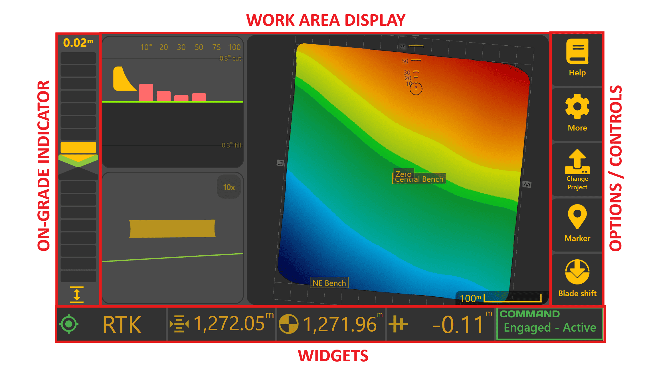
The Apply View can be divided into four main areas:
- On-Grade Indicator
- Work Area Display
- Operator Controls
- Status Widgets
Additional project information is available through the More menu when required.
On-Grade Indicator

 The On-Grade Indicator provides the quickest indication of whether the implement is currently above, below or on the target surface. During grading, it is typically the primary guidance reference used by the operator for monitoring height error.
The numerical value displayed above the indicator shows the current error between the implement position and the target surface.
- Arrow pointing up – the implement needs to be raised.
- Arrow pointing down – the implement needs to be lowered.
- Both arrows green with no coloured bars – the implement is within the configured deadband and is considered on grade.
As grading error increases, additional indicator segments illuminate to provide an immediate visual indication of how far the implement is from the target.
Deadband
A small deadband surrounds the target elevation to prevent the indicator continually changing state due to normal GNSS measurement variation.
By default, the deadband is ±1.5 cm. While within this range the indicator will appear on grade, although the numerical error value continues to display the true measured error.
 Blade Shift

Blade Shift temporarily offsets the current target above or below the design surface without changing the design itself.
When Blade Shift is active, a Blade Shift icon is displayed beneath the indicator. This reminds the operator that the current target has been intentionally offset from the design surface.
 Cut/Fill Limiting

When Dynamic Cut or Fill Limiting is enabled, the indicator normally displays the error between the implement and the limited target rather than the final design surface.
Pressing/tapping the indicator toggles between:
- Current tracking target (limited).
- Error to the final design surface.
When displaying error to the design surface, the indicator uses the current cut/fill colour scheme to show the full design error.
Work Area Display
The centre of the Apply View displays the current work area together with optional guidance views that assist the operator while grading.
The display consists of one primary viewing area and two secondary viewing areas. Each area can independently display:
- Map
- Side View
- Back View
Operators can arrange these views to suit different tasks using the Layout settings.
Examples include:
- Full-screen Map
- Map + Side View
- Map + Back View
- Side View + Back View
- Map + Side View + Back View
The purpose of each view is described below.
Map
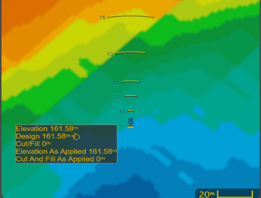 The Map displays the current project together with the machine position.
During operation it is primarily used to:
- Monitor grading progress
- Identify remaining cut and fill
- Plan efficient travel paths
- Review completed work
Selecting any point on the map displays information for that location, including surface values where available.
The displayed colours and surface layers are configurable using the Appearance settings described later in this chapter.
Side View
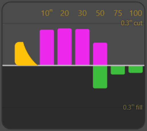 The Side View provides a preview of the terrain ahead of the implement based on the current direction of travel. Upcoming cuts and fills are displayed relative to the design surface, allowing the operator to anticipate changing ground conditions before reaching them.
As grading progresses, the preview updates using the current As Applied Cut/Fill surface, allowing the operator to see grading progress in front of the machine.
Back View
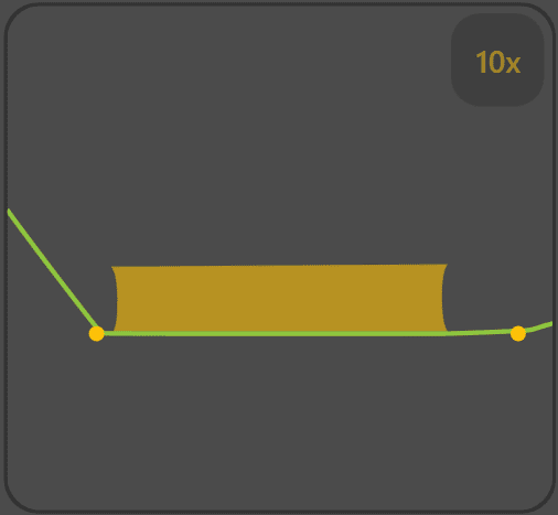
The Back View displays a cross-section across the blade width.
This view is particularly useful when grading dual-height or height & x-slope applications, allowing the operator to compare the measured surface against the design across the entire implement width.
The displayed vertical scale can be adjusted by selecting the scale indicator.
Where project linework intersects the displayed cross-section, intersection markers are also shown to assist with alignment.
Operator Controls
The More menu is the primary access point for project management, system configuration and advanced operating functions. Many procedures throughout this manual begin by opening the More menu.
Depending on the current project type, some buttons may change to provide direct access to project-specific functions such as Plane selection or Project selection.
Detailed operation of these functions is covered throughout this manual.
The primary controls include:
| Control | Purpose |
|---|---|
| Help | Opens the Level COMMAND manual. |
| More | Accesses additional settings, diagnostics and project functions. |
| Project / Plane | Changes projects or manages Plane surfaces depending on the current project type. |
| Marker | Creates project markers and benchmarks. |
| Blade Shift | Temporarily offsets the target above or below the design surface without modifying the design itself. |
Status Widgets
The widgets along the bottom of the Apply View display continuously updated operating information while grading.
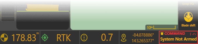
Widgets can display a wide variety of information including:
- GNSS status
- Speed
- Elevation
- Current Error
- Hydraulic information
- Position
- Cut/Fill values
The COMMAND Status widget is always displayed at the bottom-right of the Apply View and cannot be removed. It continuously reports the current operating state of the COMMAND ECU, including readiness, engagement state and any operator actions or faults requiring attention.
Widget selection and layout are fully configurable and are described in 5.3 | Widget Customisation.
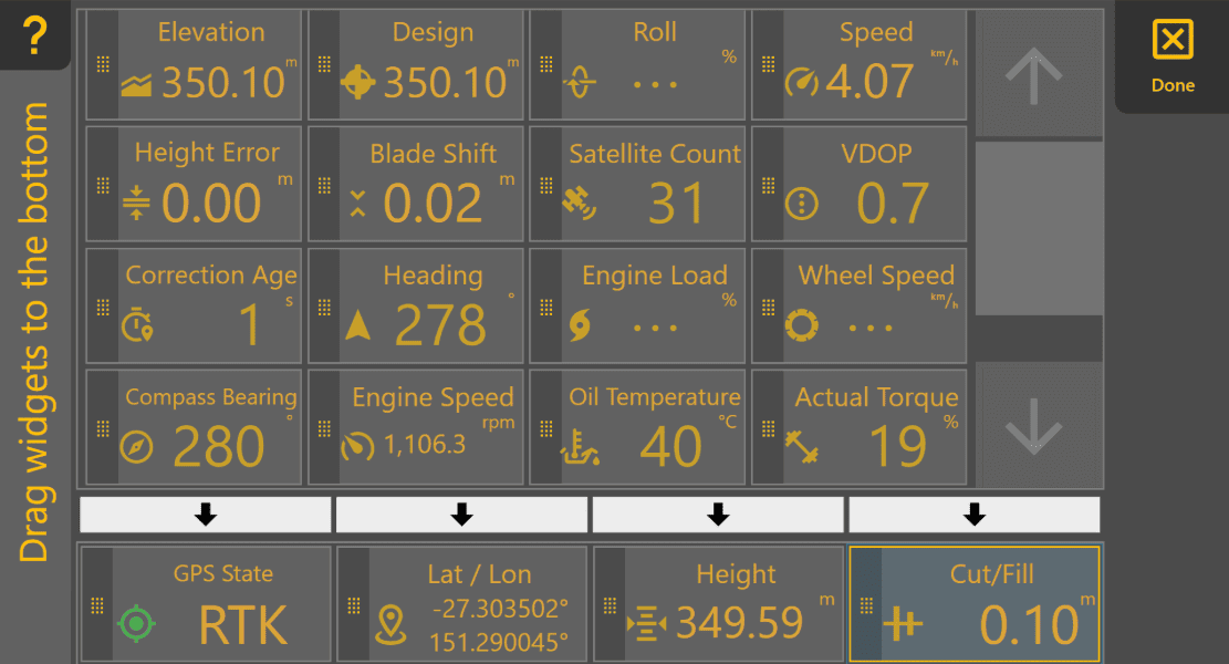
Operator takeaway: Becoming familiar with the Apply View allows you to monitor machine performance, anticipate changes in terrain and access the controls required for efficient grading without leaving the main operating screen.
Once you are familiar with the Apply View, continue to 5.2 | Apply View Layout, which explains how the display can be customised to suit different operating preferences and grading tasks.