5.1 | Apply View Overview
ThisThe viewApply View is optimizedthe toprimary getoperating youscreen movingused dirtwhile grading. It combines machine guidance, project information, Automatic Control status and isoperator splitcontrols into a fewsingle workspace, allowing the operator to monitor grading progress and operate Level COMMAND without leaving the main areasscreen.
Unlike the on-gradeQuick indicatorStart chapter, which focuses on getting the left,machine mapoperating, this section explains the purpose of each area of the Apply View and implementhow viewsthey inwork thetogether center,during optionnormal buttons on the right, status widgets along the bottom, and a title card at the top.
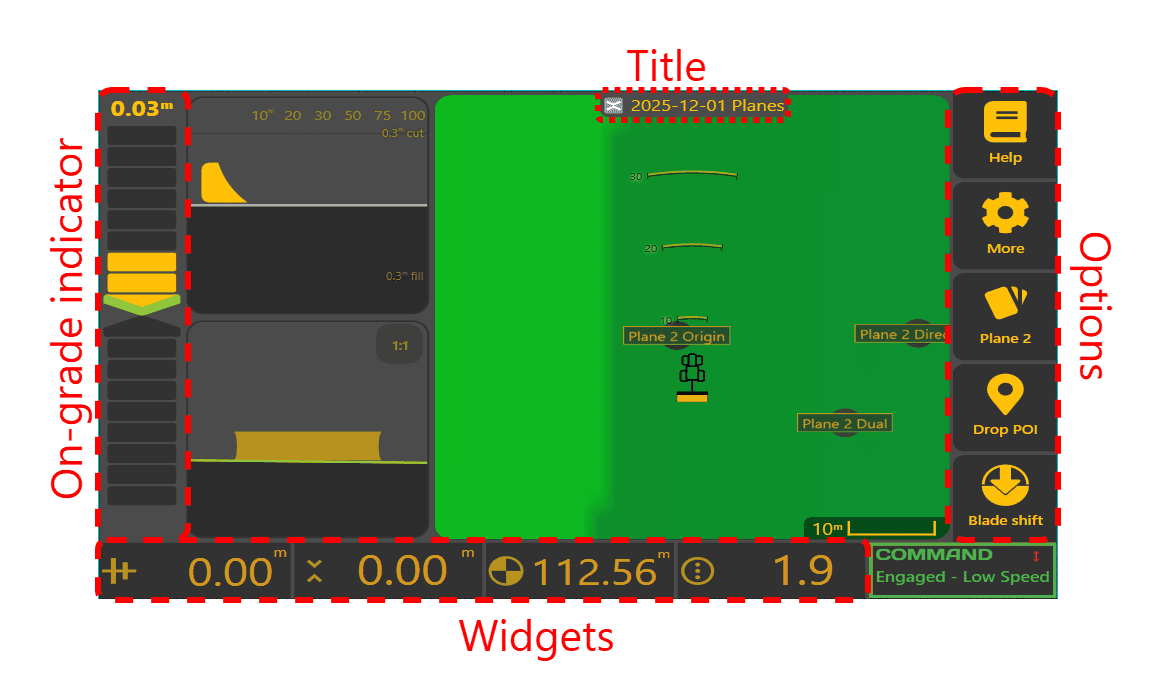
Left: On-grade indicator

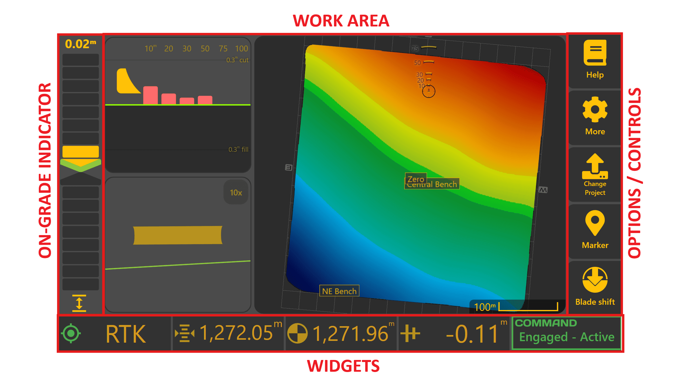
The on-gradeApply indicatorView displayscan be divided into four main areas:
Additional project information is available through the distanceMore betweenmenu when required.
On-Grade Indicator

 The On-Grade Indicator provides the
 currentquickest implementindication heightof and the design target height - this is referred to as Error. Ifwhether the implement is toocurrently high,above, abelow chevronor on the target surface. During grading it is typically the primary guidance reference used by the operator.
The numerical value displayed above the indicator shows the current error between the implement position and blocksthe target surface.
As grading error increases, additional indicator segments illuminate to provide an immediate visual indication of how far the implement is from the target.
Deadband
A small deadband surrounds the target elevation to prevent unnecessary indication changes caused by very small measurement variations.
By default, the deadband is ±1 toocm. low,While within this range the indicator will appear on grade, although the numerical error value continues to display the true measured error.

Blade Shift
When Blade Shift is active, a chevronBlade andShift blocks below will be highlighted (forming an arrow pointing up). The larger the error, the larger the arrow will be. Control erroricon is alsodisplayed shown numerically abovebeneath the indicator. InThis reminds the exampleoperator shown onthat the left,current target has been intentionally offset from the bladedesign is 5cm (2 inches) too high.surface.
If
Cut/Fill haveLimiting
When theDynamic the blade upCut or down, a 
hint will be shown at the bottom left.
If Cut/Fill limitingLimiting is enabled, tappingthe onindicator normally displays the on-grade indicator will switcherror between showingthe distanceimplement toand the limited target andrather distancethan the final design surface.
Pressing/tapping the indicator toggles between:
When displaying error to the design surface, the indicator uses the current cut/fill colour scheme to show the full design error.
Dead
Work BandArea / Zero Cut Fill range
Display
AllThe centre of the on-gradeApply indicatorsView havedisplays athe "dead-band",current orwork zero-cut/fillarea range.together Thiswith optional guidance views that assist the operator while grading.
The display consists of one primary viewing area and two secondary viewing areas. Each area can independently display:
Operators can arrange these views to suit different tasks using the Layout settings.
Examples include:
The purpose of each view is adescribed smallbelow.
Map
 The
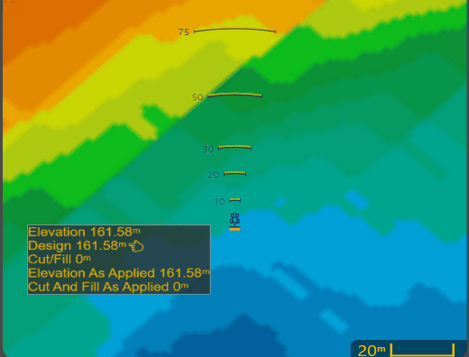
The whichMap displays the current project together with the machine position.
During operation it is ±1.5cm)primarily thatused willto:
Selecting correctany error.point Foron the map view,displays information for that location, including surface values where available.
The displayed colours and surface layers are configurable using the Appearance settings described later in this willchapter.
Side thatView
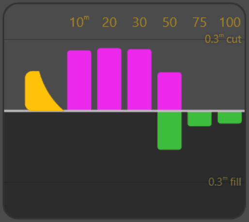 The
The withinSide View provides a preview of the rangeterrain will be considered as zero cut/fill.
Centre: Map and Implement Views
This displays your current location and optionally a side and back viewahead of your implement. This can be configured in the "Layout"implement Settings
Map
project,direction withof travel.
Upcoming cuts and fills are displayed relative to the implementdesign positionedsurface, inallowing the center.operator Visitto anticipate changing ground conditions before reaching them.
As grading progresses, the Appearancepreview pageupdates using the current As Applied Cut/Fill surface, allowing the operator to setsee differentgrading colour schemes. The implement is shown at its current location, with radar arcsprogress in front of the tractor. The radar arcs show where cuts and fills are sampled for the side view (see below). Tapping anywhere on the surface will open an information window containing various values for the tapped location (see left).machine.
Back
Side view
View
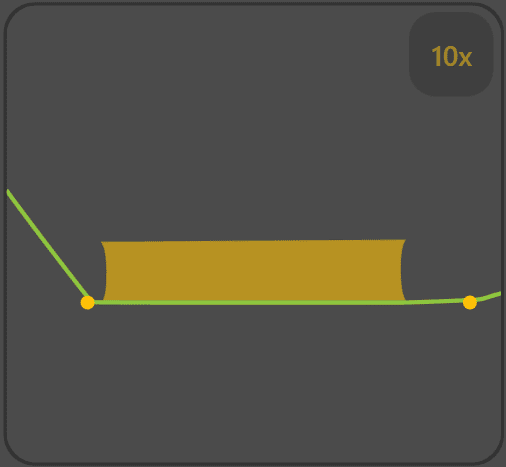
The sideBack View displays a cross-section across the blade width.
This view showsis upcomingparticularly cutsuseful andwhen fillsgrading assumingsurfaces requiring accurate cross-fall or X-Slope control, allowing the currentoperator headingto iscompare maintained.the measured Asurface a central horizontal line 'design line' indicatesagainst the design height. Bars for cut and fill are shown above and belowacross the designentire line.implement When an area requires cutting, a pink or red bar is shown above the design line depending on cut/fill colour scheme. When an area requires filling, a green or blue bar is shown below the design line depending on colour scheme. An area may require both cuts and fills, and in that case, both bars will be shown (see left).width.
The cutdisplayed andvertical fill bars are sampled from the As Applied Cut/Fill layer, so as more earthmoving is completed, the bars will reduce in size. The As Applied Cut/Fill layerscale can be viewed in the map area during workadjusted by selecting the 'Asscale Cut/fill'indicator.
Where inproject linework intersects the Appearancedisplayed page.
Backintersection view
markers 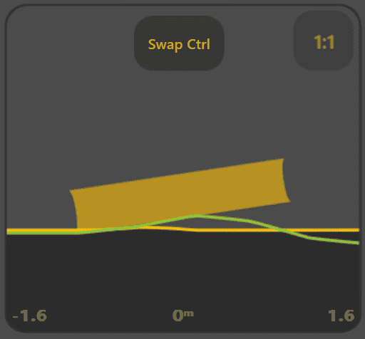
Back view
Operator theControls
The designright-hand surfacetoolbar isprovides shownquick in green, and the elevation surface is shown in the primary color (defaults to amber). Tap the scale badge in the top right to change the vertical scale. Tap anywhere else to show the legend and horizontal distance labels for a few moments.
If single point control is being used, a Swap Ctrl button is shown, which will move the control point from one side of the bladeaccess to the other.functions Seemost Bladecommonly Controlused Settingswhile for more.grading.
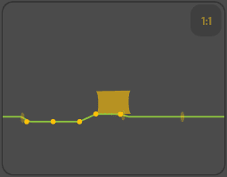
Any linework that crosses the Back view will be shown via small marks (see right). Linework that has elevation values will be shown as small solid circles, and linework that has no elevation values will be shown as a semi-transparent ellipses (see the right-most mark). To help prevent overloading, at most 3,200km of linework will be checked, and up to 30 linework intersections will be displayed at a time.
Top: Title card
TapDepending on the current project nametype, atsome buttons may change to provide direct access to project-specific functions such as Plane selection or Project selection.
Detailed operation of these functions is covered throughout this manual.
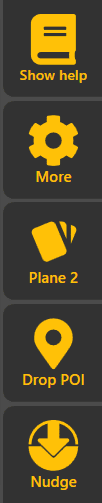
The primary controls include:
Right:
On
NOTE: To exit Level COMMAND, simply tap the More button, then tap the Close App button.
Bottom:
Status widgets
Widgets
The small rectangleswidgets along the bottom of the screenApply View display continuously updated operating information while grading.
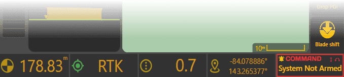
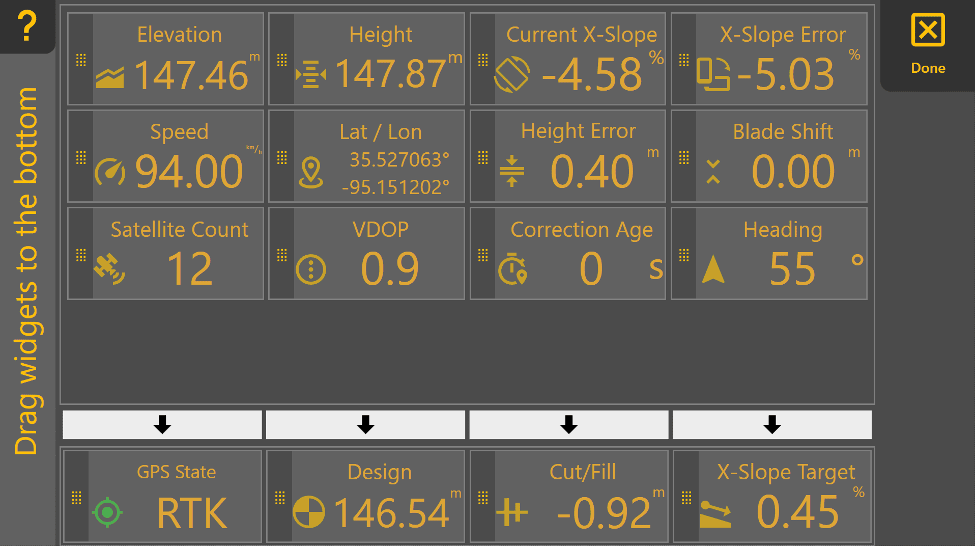
Widgets can display a wide variety of information including:
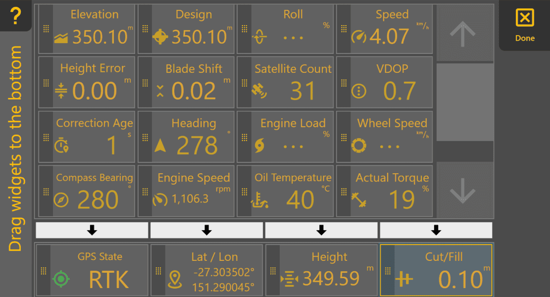
Widget selection and layout are fully configurable . Long-press on a widget to open the Widget Settings and change the displayed widgets. There are manydescribed toin select5.3 from,| soWidget tryCustomisation.
The tillCOMMAND you've found the ones that best suit your needs. Notet that the right-mostStatus widget is always displayed at the COMMANDbottom-right statusof widgetthe Apply View and cannot be changed.
Thecontinuously namereports the current operating state of each widget is shown in Widget Settings, so to check their names, just long-press on one (except the COMMAND ECUwidget, onincluding readiness, engagement state and any operator actions or faults requiring attention.
Once you are familiar with the right).purpose of each area of the Apply View, continue to 5.2 | Apply View Layout, which explains how the display can be customised for different operating preferences and grading tasks.