5.1 | Apply View Overview
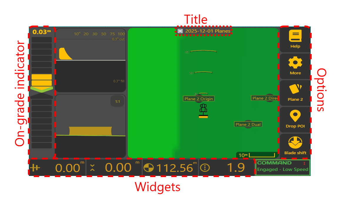
This view is optimized to get you moving dirt and is split into a few main areas - the on-grade indicator on the left, map and implement views in the center, option buttons on the right, status widgets along the bottom, and a title card at the top.
Left: On-grade indicator


The on-grade indicator displays the distance between the current implement height and the design target height - this is referred to as Error. If the implement is too high, a chevron and blocks above the mid-point will be highlighted (forming an arrow pointing down). If the implement is too low, a chevron and blocks below will be highlighted (forming an arrow pointing up). The larger the error, the larger the arrow will be. Control error is also shown numerically above the indicator. In the example shown on the left, the blade is 5cm (2 inches) too high.
If you have shifted the the blade up or down, a  hint will be shown at the bottom left.
If Cut/Fill limiting is enabled, tapping on the on-grade indicator will switch between showing distance to the limited target and distance to the final design (see right).
Dead Band / Zero Cut Fill range
All of the on-grade indicators have a "dead-band", or zero-cut/fill range. This is a small range (3cm which is ±1.5cm) that will be considered on-grade - note that the numerical value at the top right will still reflect the correct error. For the map view, this will mean that anything within the range will be considered as zero cut/fill.
Centre: Map and Implement Views
This displays your current location and optionally a side and back view of your implement. This can be configured in the "Layout" Settings
Map
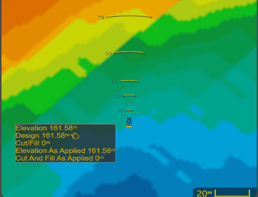 The map area shows the surface data contained in the current project, with the implement positioned in the center. Visit the Appearance page to set different colour schemes. The implement is shown at its current location, with radar arcs in front of the tractor. The radar arcs show where cuts and fills are sampled for the side view (see below). Tapping anywhere on the surface will open an information window containing various values for the tapped location (see left).
Side view
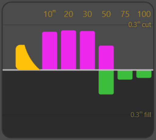
The side view shows upcoming cuts and fills assuming the current heading is maintained. A a central horizontal line 'design line' indicates the design height. Bars for cut and fill are shown above and below the design line. When an area requires cutting, a pink or red bar is shown above the design line depending on cut/fill colour scheme. When an area requires filling, a green or blue bar is shown below the design line depending on colour scheme. An area may require both cuts and fills, and in that case, both bars will be shown (see left).
The cut and fill bars are sampled from the As Applied Cut/Fill layer, so as more earthmoving is completed, the bars will reduce in size. The As Applied Cut/Fill layer can be viewed in the map area during work by selecting the 'As Cut/fill' button in the Appearance page.
Back view
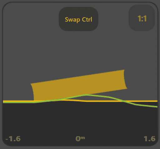
Back view shows the elevation and target profile across the blade inline with the direction of travel. The design surface is shown in green, and the elevation surface is shown in the primary color (defaults to amber). Tap the scale badge in the top right to change the vertical scale. Tap anywhere else to show the legend and horizontal distance labels for a few moments.
If single point control is being used, a Swap Ctrl button is shown, which will move the control point from one side of the blade to the other. See Blade Control Settings for more.
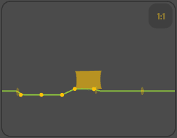
Any linework that crosses the Back view will be shown via small marks (see right). Linework that has elevation values will be shown as small solid circles, and linework that has no elevation values will be shown as a semi-transparent ellipses (see the right-most mark). To help prevent overloading, at most 3,200km of linework will be checked, and up to 30 linework intersections will be displayed at a time.
Top: Title card
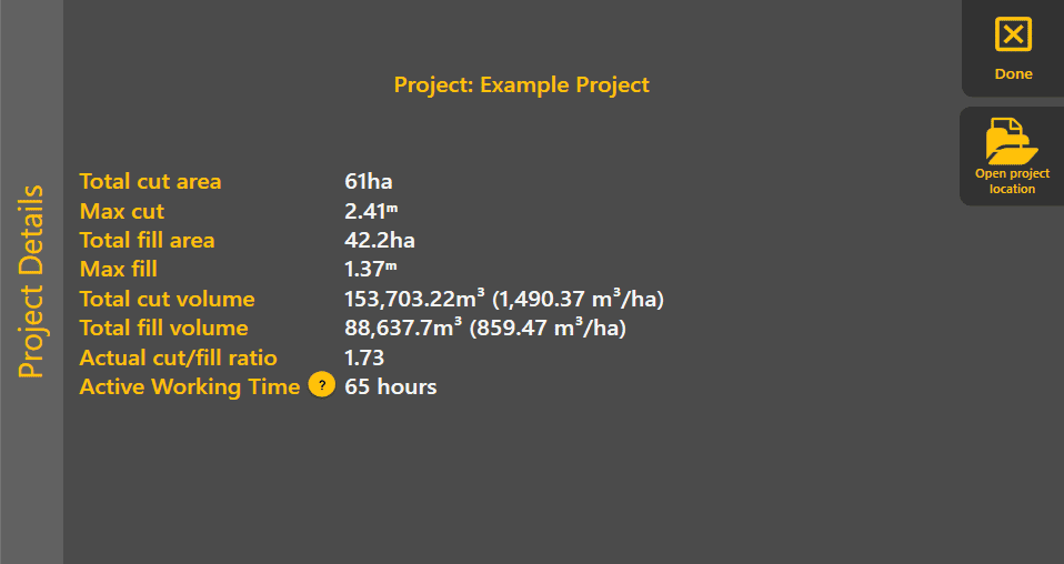
Tap on the project name at the top to view the project title card and details about the current project.
Right: Option Buttons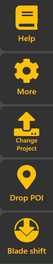
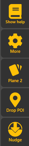
On the right, several buttons allow you to operate and configure Level COMMAND. Tap one of them to show more details.
- Help displays the help guide.
- More will expand a list of settings groups and other actions for you to choose from.
- The third button changes depending on what type of project you're working on:
- For imported designs, Change Project lets you switch between different projects.
- For planes, Planes lets you switch between planes and configure them. To switch projects, use the More button and press Load Proj at the top left.
- Drop POI allows you to drop a Point Of Interest (POI) at your current location.
- Blade shift allows you offset the blade's target height from the design elevation. This allows you to offset the target upward or downward.
NOTE: To exit Level COMMAND, simply tap the More button, then tap the Close App button.
Bottom: Status widgets
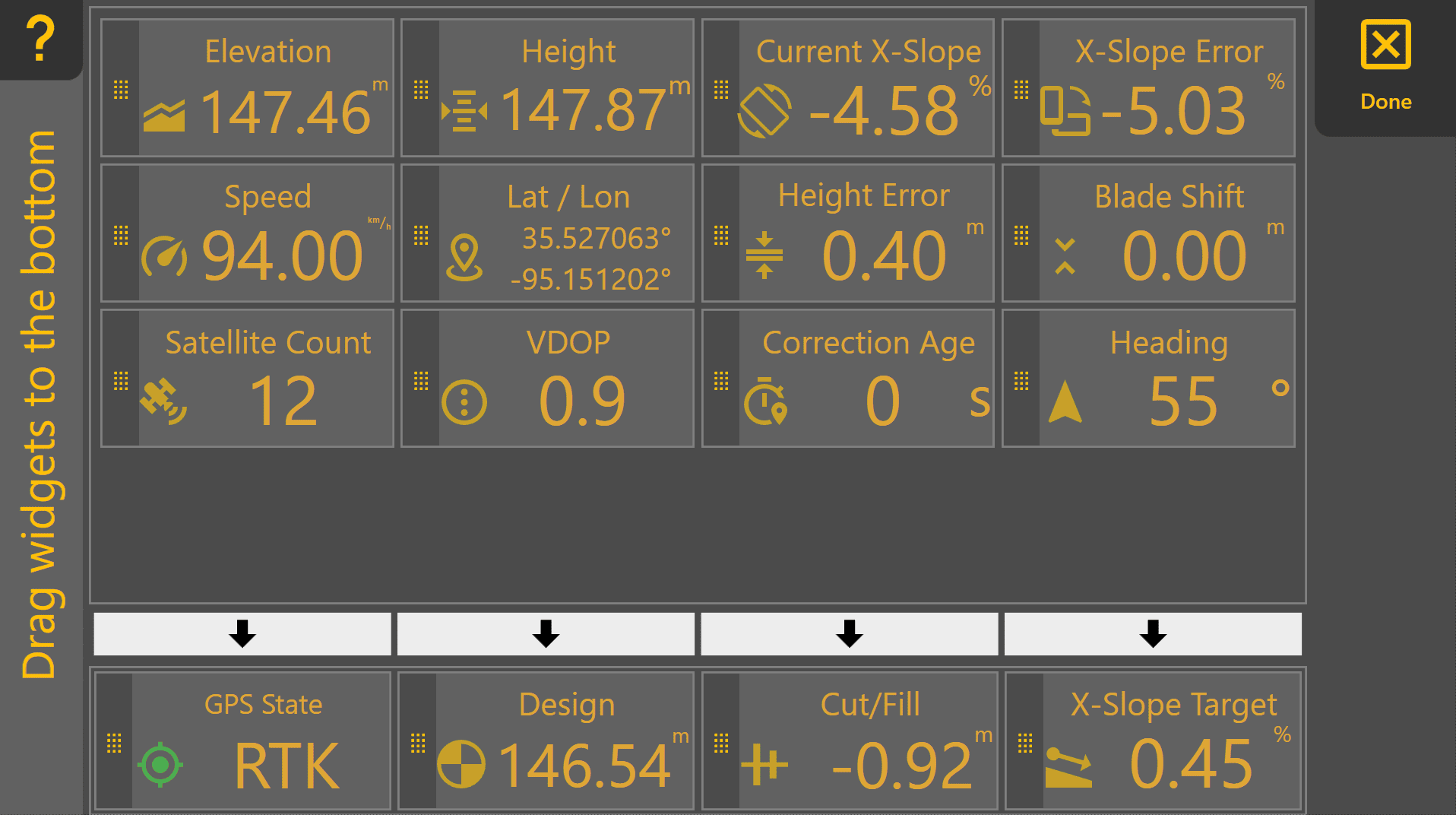
The small rectangles along the bottom of the screen are configurable . Long-press on a widget to open the Widget Settings and change the displayed widgets. There are many to select from, so try them out till you've found the ones that best suit your needs. Notet that the right-most widget is always the COMMAND status widget and cannot be changed.
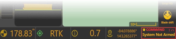
The name of each widget is shown in Widget Settings, so to check their names, just long-press on one (except the COMMAND widget on the right).