4.3 | Loading or Creating a Project
Loading a Design File
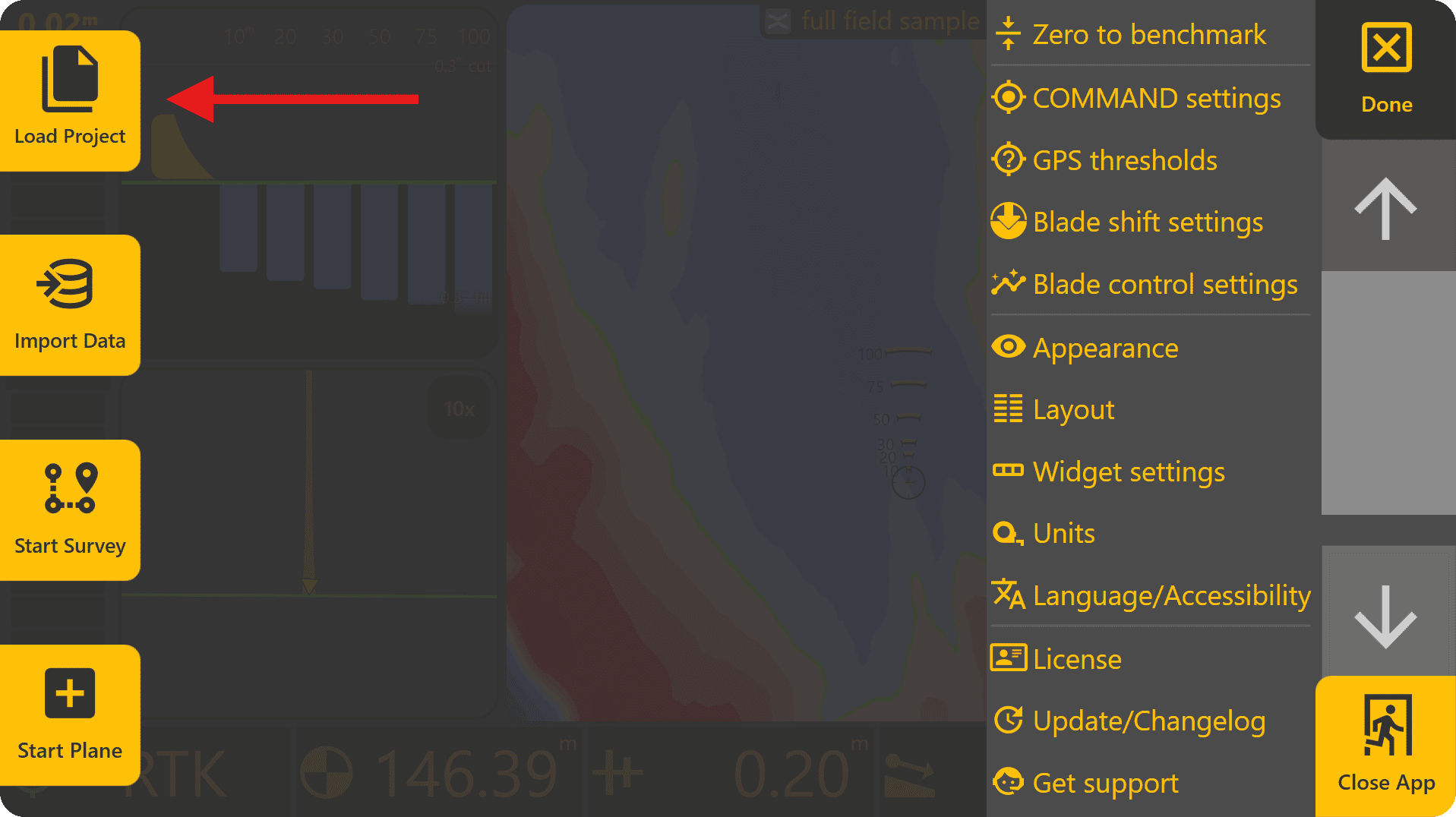
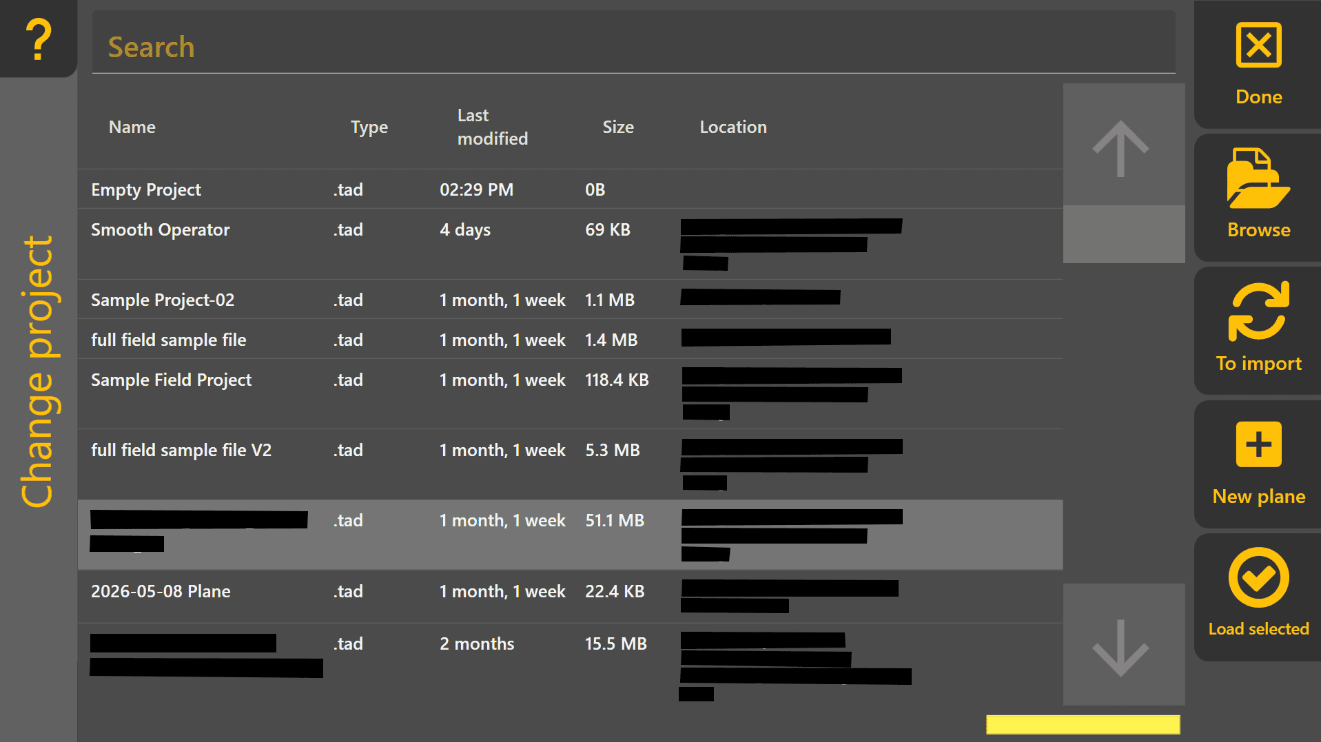
To load a design file, press Done at the top-right to return to the Level COMMAND apply page, then press More > Load Project. This will open the Change Project page and display all .tad file projects. This file type is specific to LC and the software will automatically scan the file system to find all .tad files present - alternatively to find them manually press "Browse" on the right side of the screen to find them manually.
Supported design formats:
• T3RRA Project (.tci)
• GPS Design (.gps)
• Existing Level COMMAND Plane Projects
 Loading an Existing Level COMMAND Project
If loading an existing Level COMMAND project (.tad file type), select it from the list and press Load Selected.

Loading an External Design File (Other File Types)
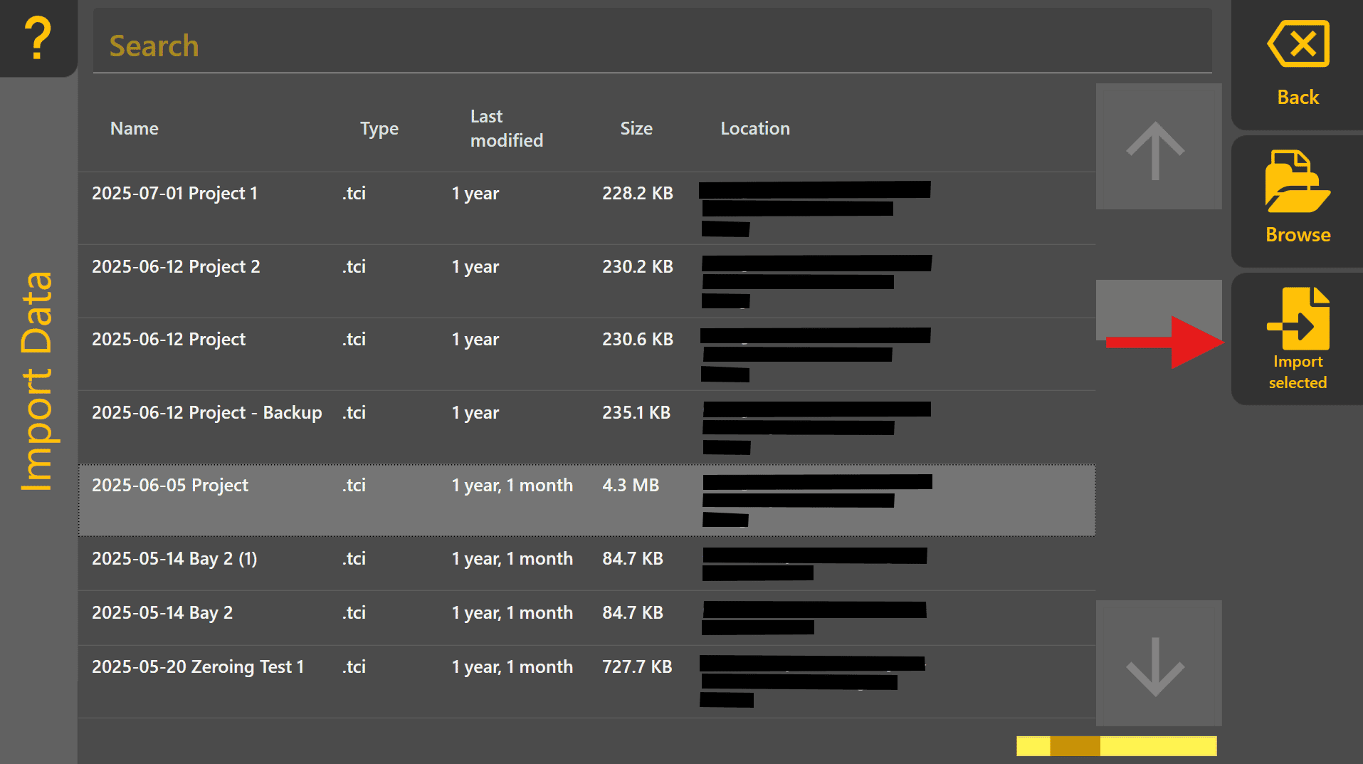
If loading a design of different file type, such as .tci, press "To Import" to move to the Import Data page. Select the design file from the list and then press "Import Selected".
Creating a Basic Plane Project
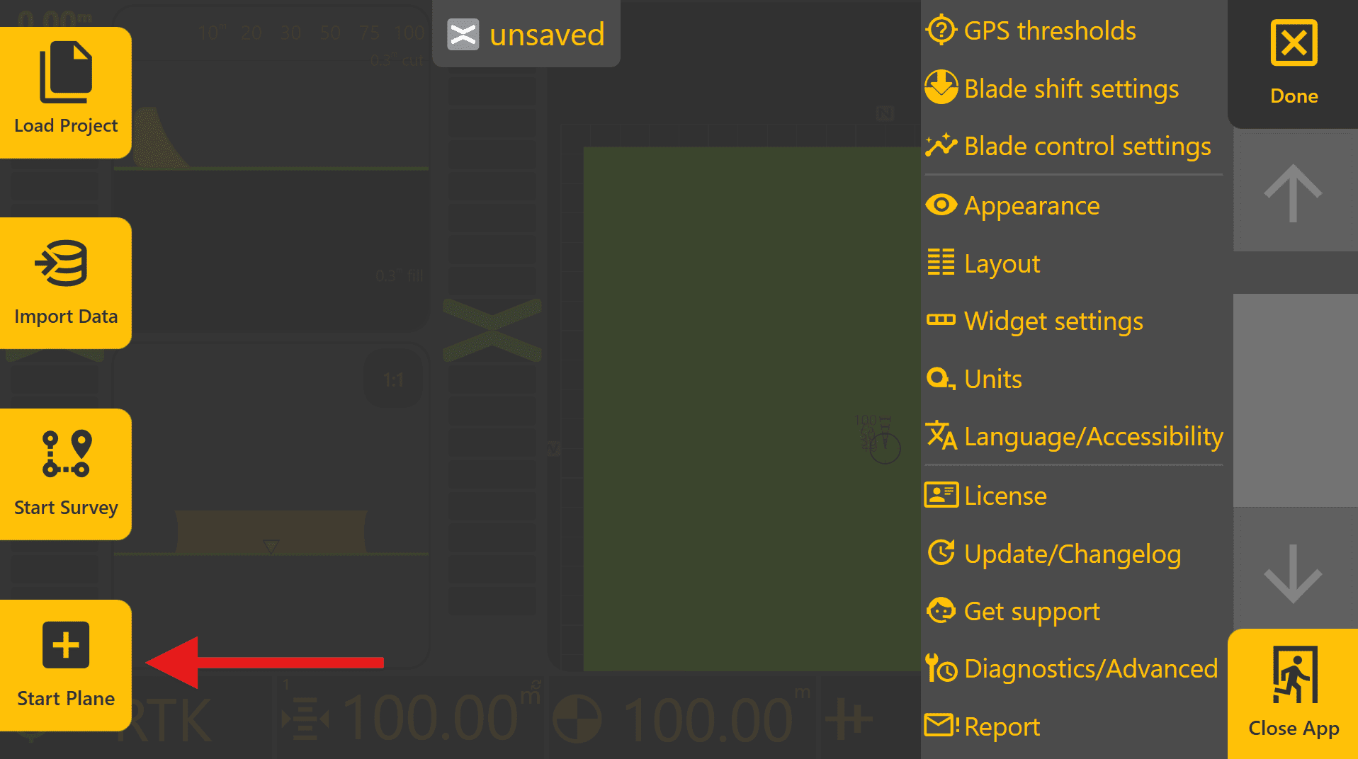
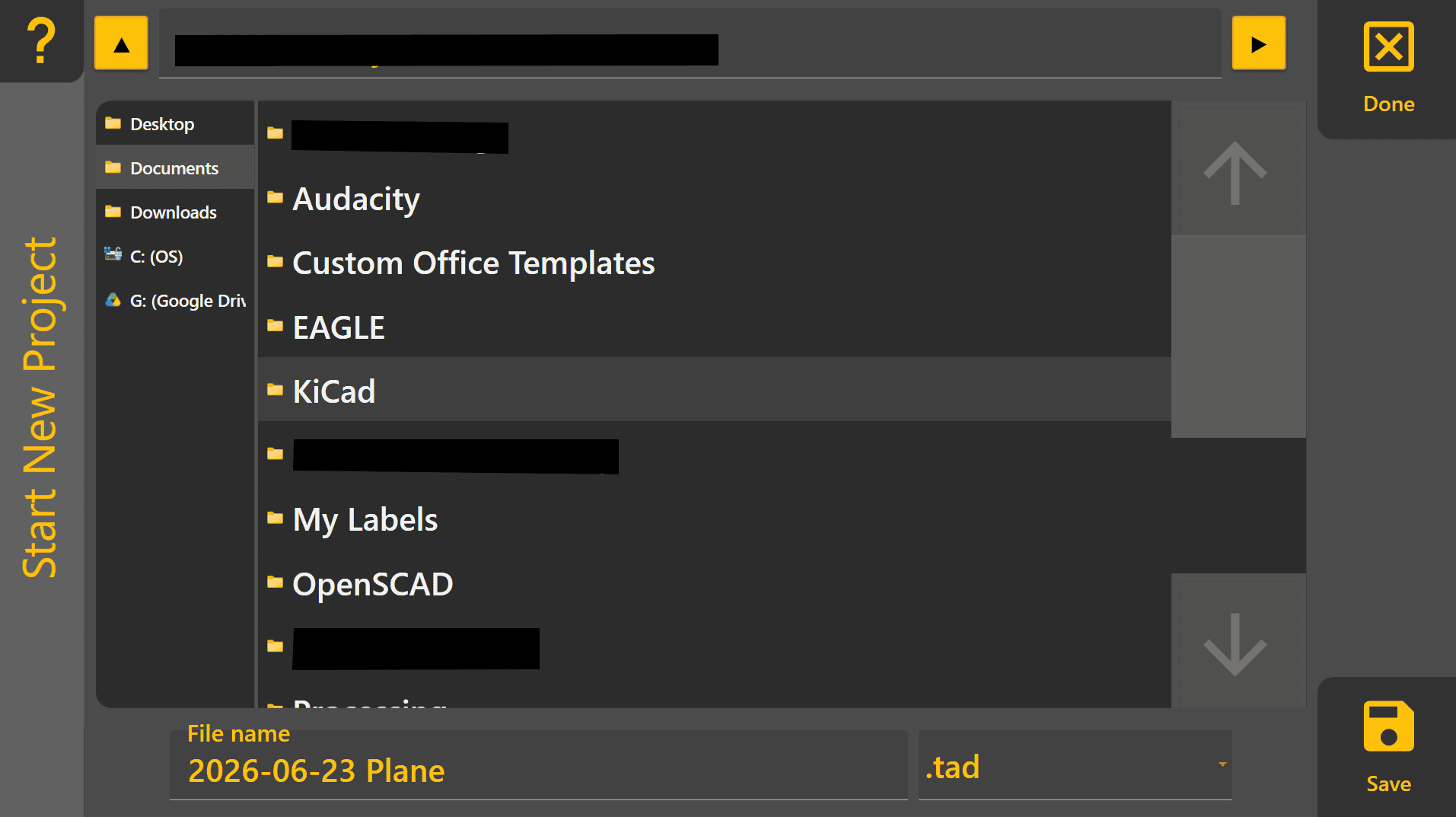
To create a basic 2D/3D plane project, begin by pressing More > Start Plane. Choose an appropriate location to save the plane project on the tablet PC and then name the project, then press "Save".
Creating a Basic Plane Project
A Plane project is the quickest way to begin using Level COMMAND without importing an existing design. Plane projects are commonly used for machine testing, simple levelling work and creating flat pads.
To create a Plane project:
- Press More → Start Plane.
- Enter a project name and choose a save location.
- Press Create Plane.
- Press Planes, then select one of the available Plane slots.
- Press Create.
- Press Origin and then Use GPS to set the Plane origin to the current implement position.
- Press Okay to create a flat Plane surface.
The Plane can now be loaded and used for testing or levelling work.
If a sloped surface is required, press Slope and use Use GPS at a second location to automatically calculate the desired slope.
For detailed information on Plane projects, refer to Section 5 | Operational Workflows.
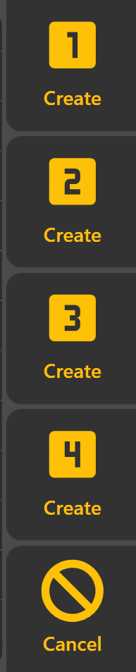
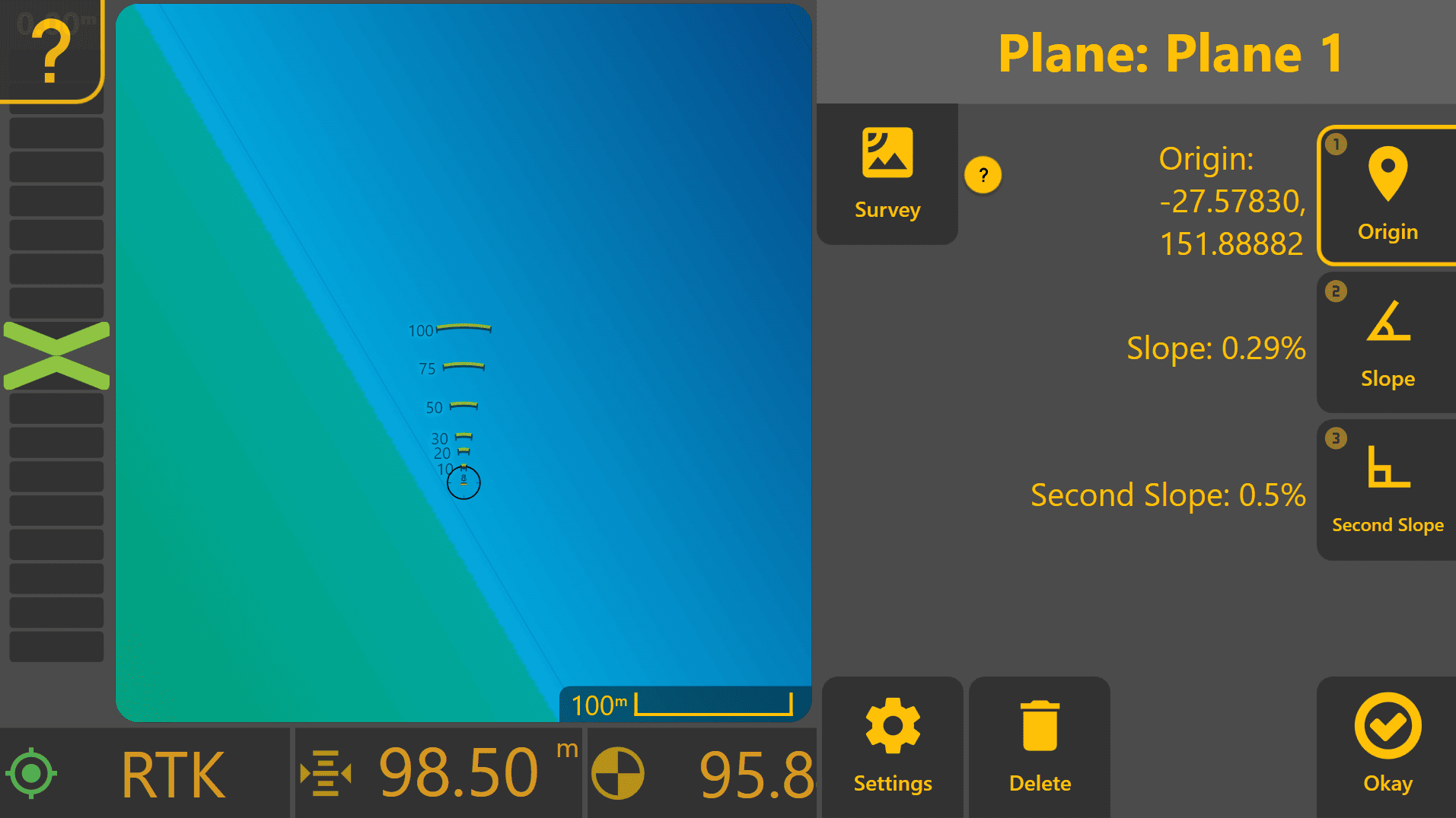
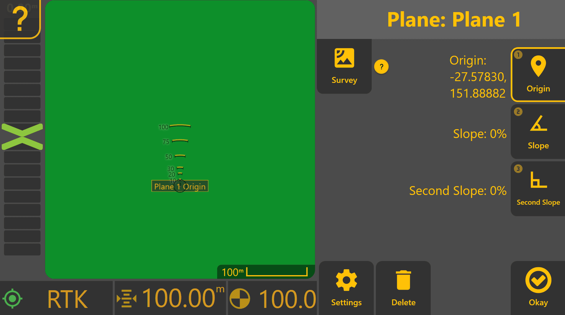
To begin designing a Plane, press the "Planes" button at the right side of the screen, then "Create" for one of the available plane slots (1-4). Up to four Plane surfaces can be stored within a project, making it easy to switch between different work areas without creating additional projects. Once pressed, a Plane design area will appear at the right side on top of the Apply View.
Plane Settings
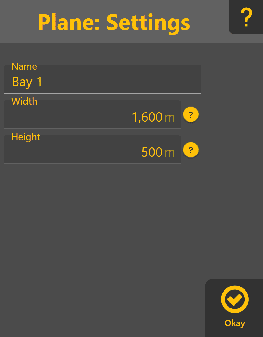
Press "Settings" to view the Plane Name and size (Width and Height). Name the Plane to make it easier to reference within the work area, and adjust the size of the Plane as needed to avoid the entire surface extending past the work area if desired. These settings can be adjusted later if needed.
Setting the Origin Point
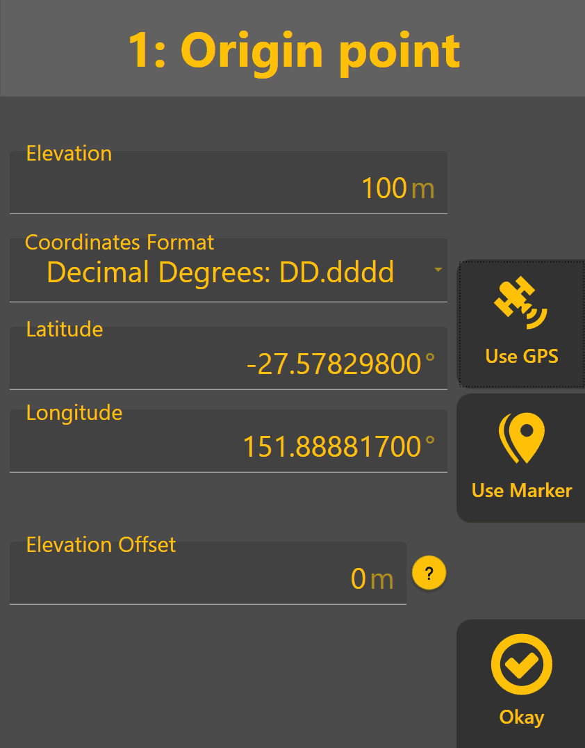
Follow through steps 1-3 at the right side. Press Origin to define the Plane origin point. Press "Use GPS" to set the origin point to the current elevation of the implement GNSS receiver. Alternatively, Lat/Lon/Elev coordinates can be entered manually if using a surveyed benchmark for the Plane design. Once set, press "Okay" and a flat-grade Plane will be created with the origin point at the centre.
To quickly move the plane up (e.g. for filling in the work area) or down (e.g. for flattening and removing top soil or undulations) later, an Elevation Offset can be applied to the Plane origin point using the Elevation Offset field and will shift the Plane upward with a positive value or downward with a negative value.
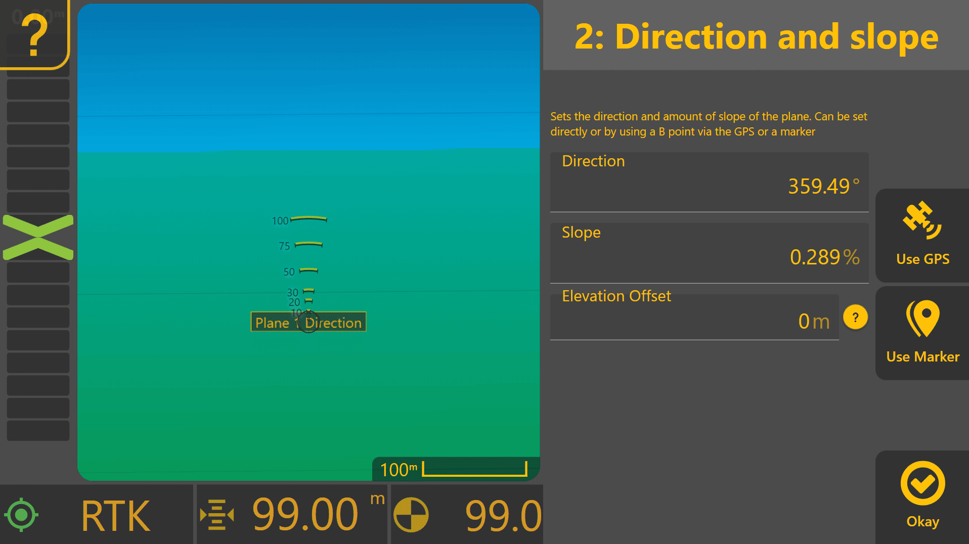
Setting the Primary Slope
The Secondary Slope is applied at right angles to the Primary Slope. Press the "Slope" button to design the primary slope of the Plane. Drive from the Plane origin to a second point on the desired grade surface, place the blade on the ground and then press Use GPS. The slope between the origin point and the slope marker will be generate automatically and displayed as well as the Plane surface updating with the new slope on the map. Direction and slope from the origin point can also be entered manually here. Once finished, press "Okay".
Setting the Secondary Slope
Press the "Second Slope" button to design the secondary slope of the Plane. Drive from the Plane origin to the desired secondary high-point or low-point in the work area, place the blade on the ground and then press "Use GPS" to set the Plane's second slope marker to the current implement height and calculate the secondary slope automatically.
Alternatively, enter the secondary slope percentage manually in the field shown to apply a known secondary slope across the the entire plane, cross-sectionally to the primary slope.
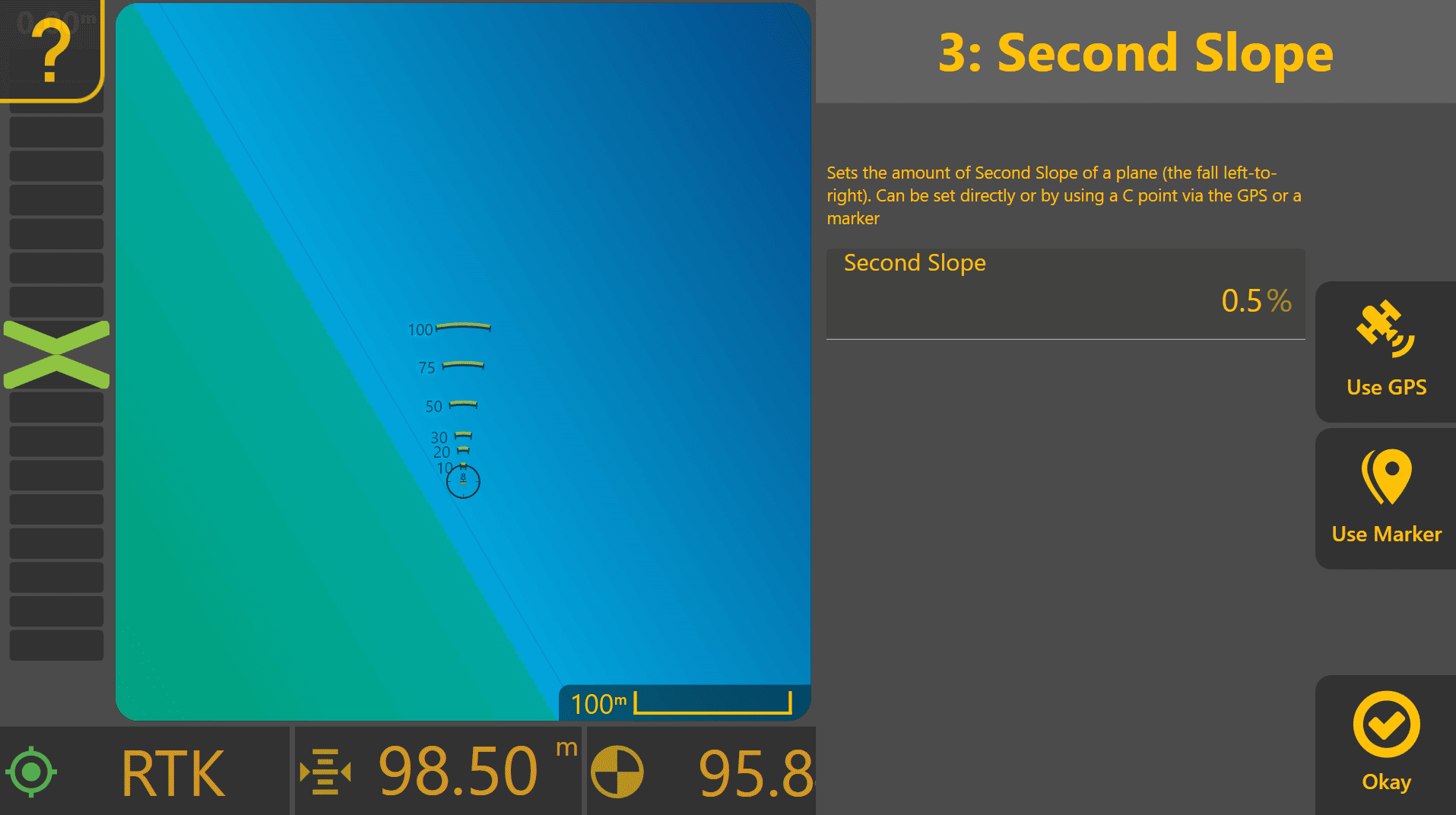
The overall slope and direction of the Plane is then be calculated based on differences between heights at the origin point, primary slope marker and second slope marker. Press "Okay" to finish.