4.1 | System Startup
Start!
When Level COMMAND is first started, you'll be greeted by the apply page below:
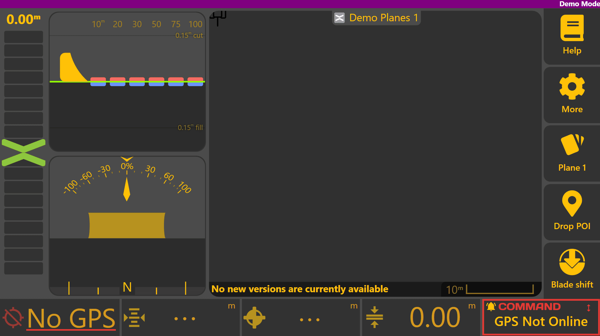
Once all hardware components have been fitted, the COMMAND ECU needs to be set up for the correct configuration to operate Level COMMAND.
Creating a Basic Plane
To create a basic plane, begin by pressing More > Start Plane, then name the plane project and choose where it should be saved. Begin designing a plane by pressing Create Plane at the bottom right (or alternatively the Planes button and then select one of the Plane slots).
Set the height of the implement cutting edge about 20cm / 0.5ft above the ground surface to begin with and set the origin. If working on a steeply sloped area, you may want to "drive-out" the primary slope using the plane tool and can then test control above the surface without risking implement contact with the ground.
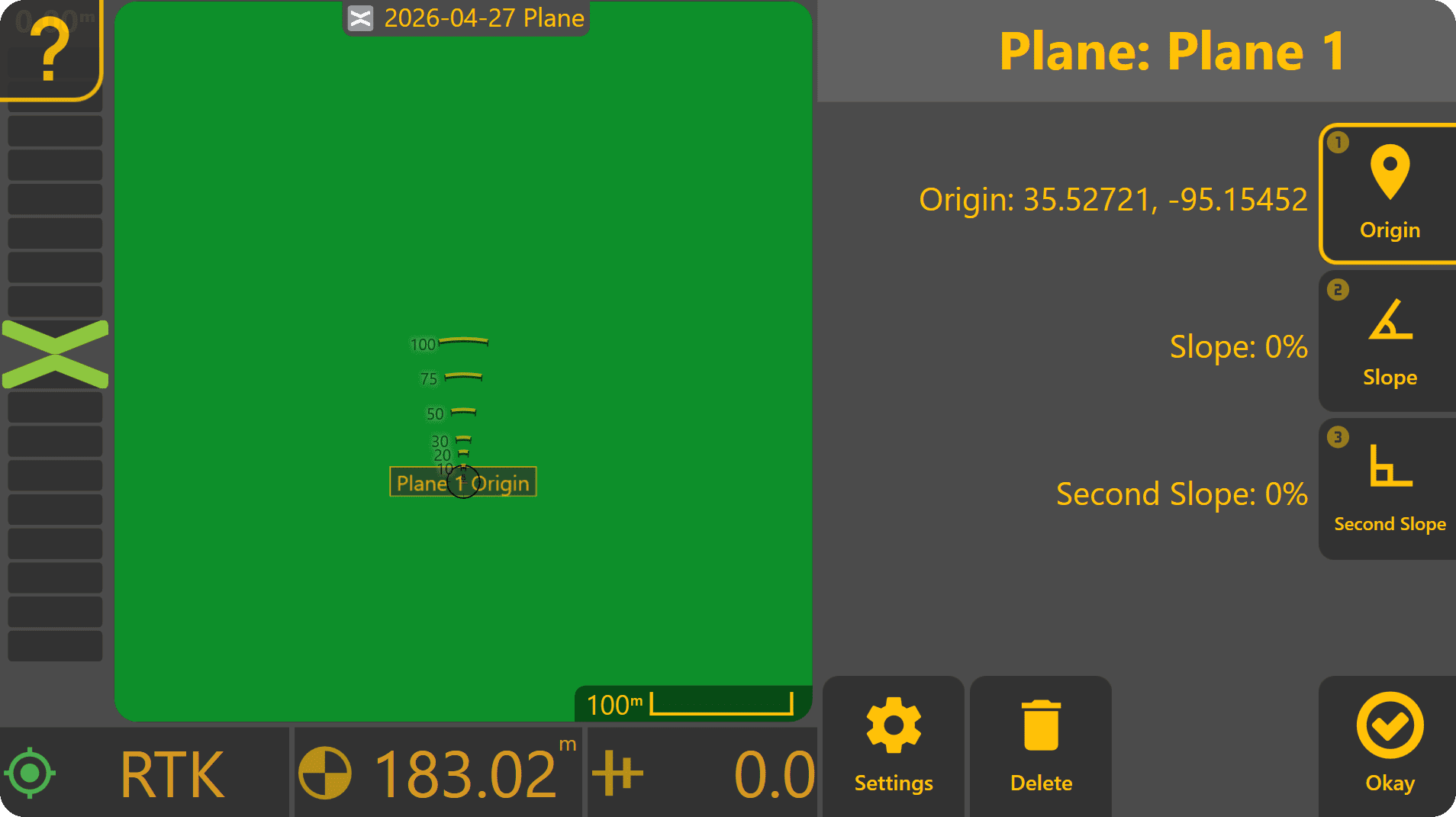
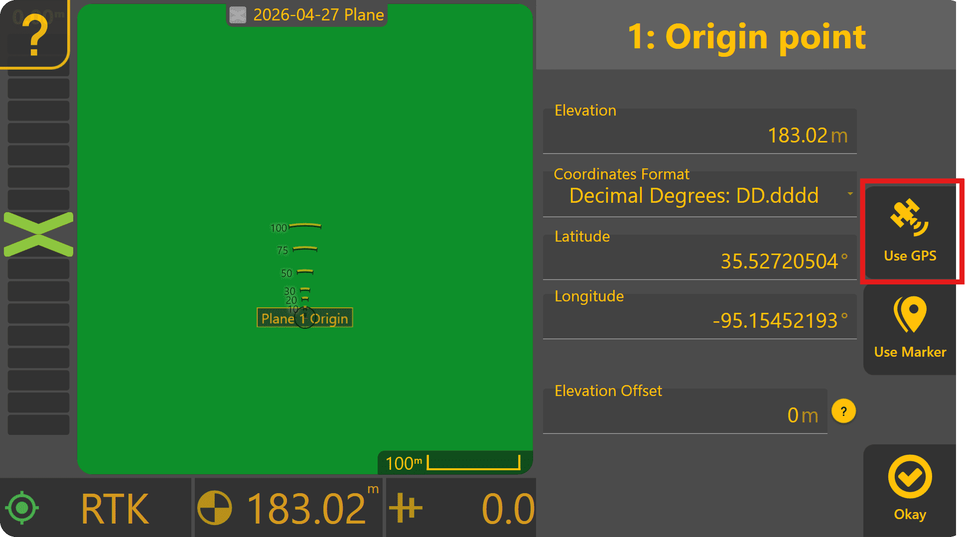
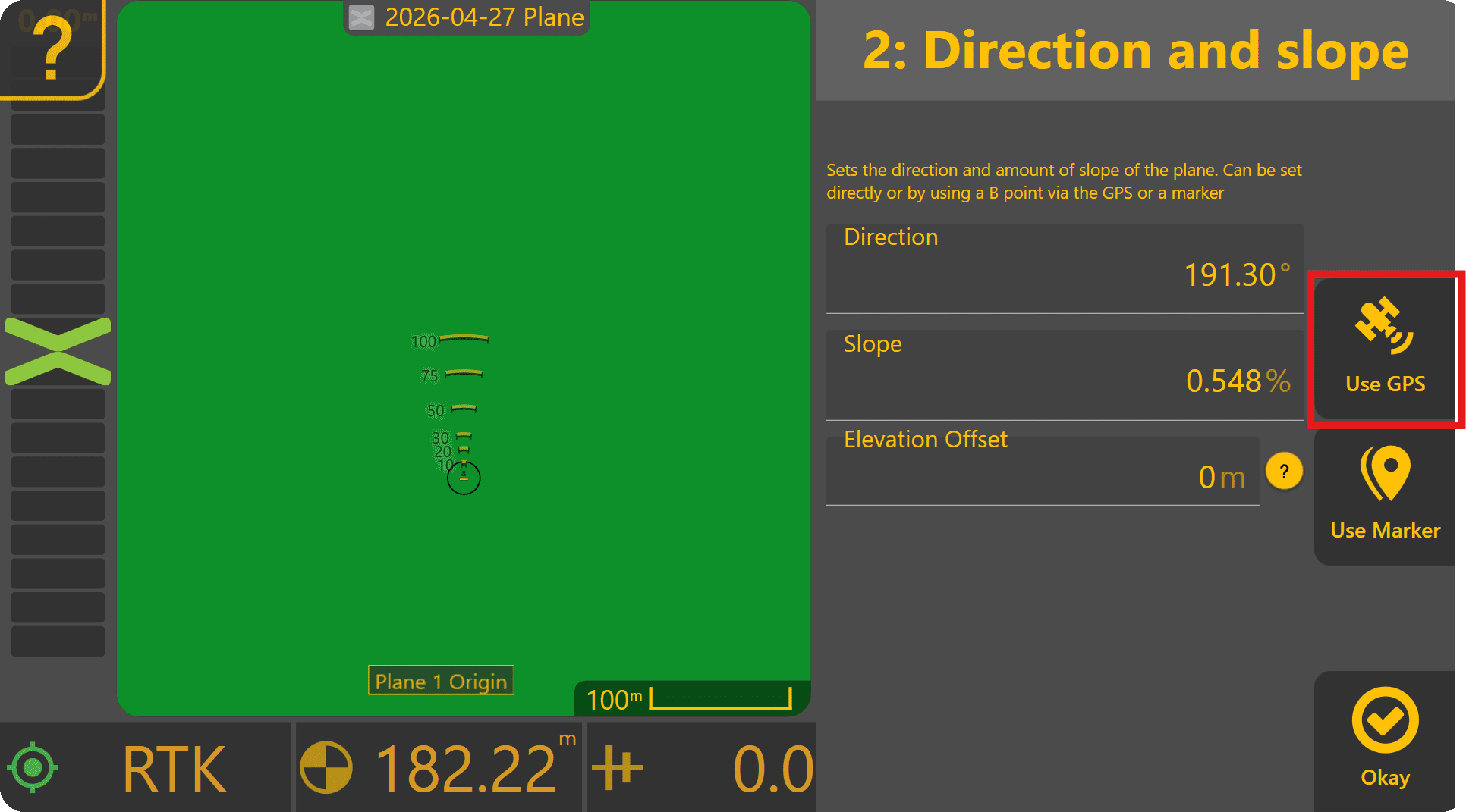
Press Origin to edit the plane's origin point. Press Use GPS to set the plane origin to the current implement height.
Press Okay - a flat plane has now been created at the origin point. If testing on a slope, press Slope, then drive from the origin point to the lowest point of the surface. Press Use GPS to set the slope point to the current implement height - the plane should now have a new slope angle and direction.
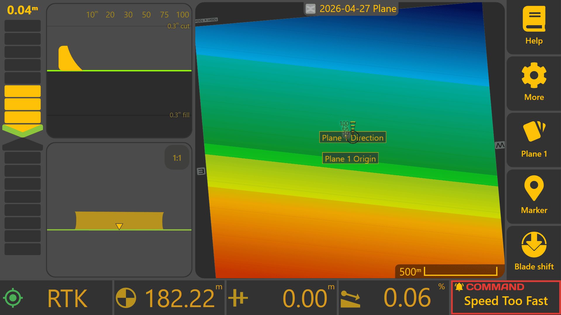
Preliminary Tuning - Air-levelling / Air-grading
Press More > COMMAND Settings > Tuning.
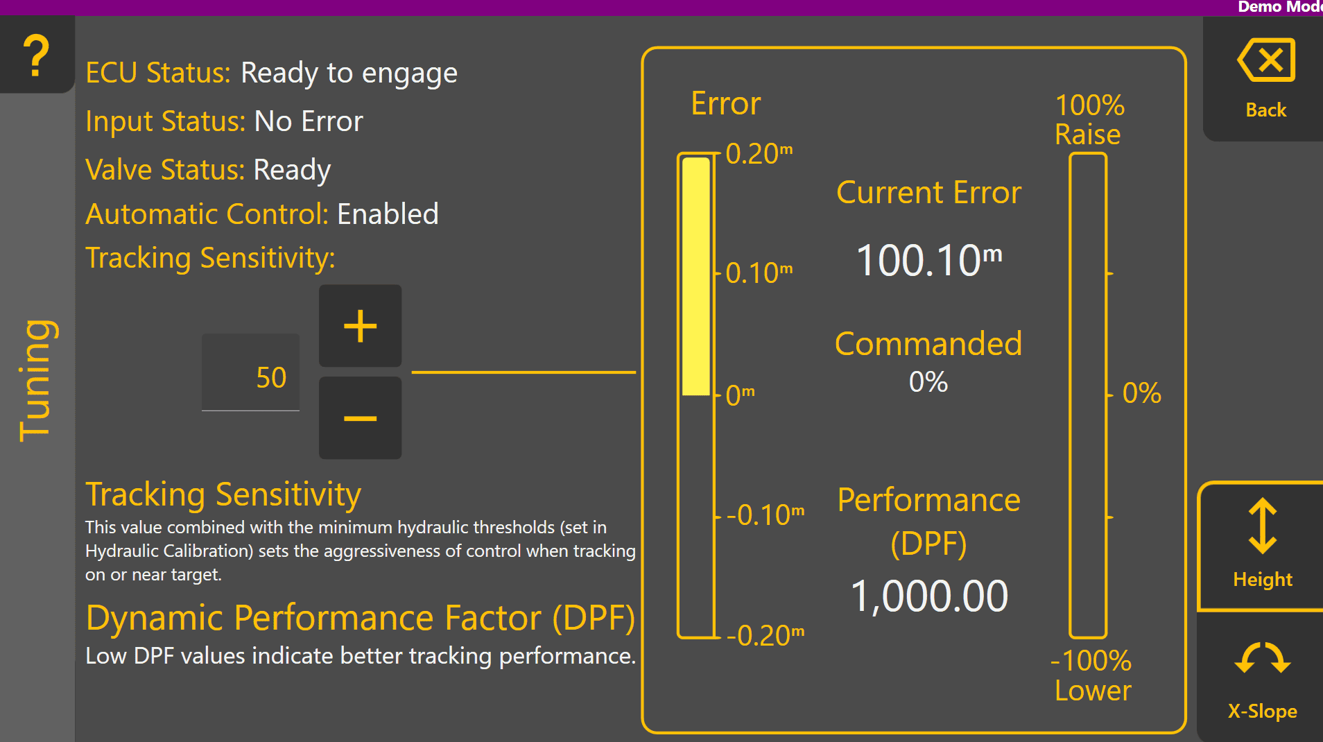
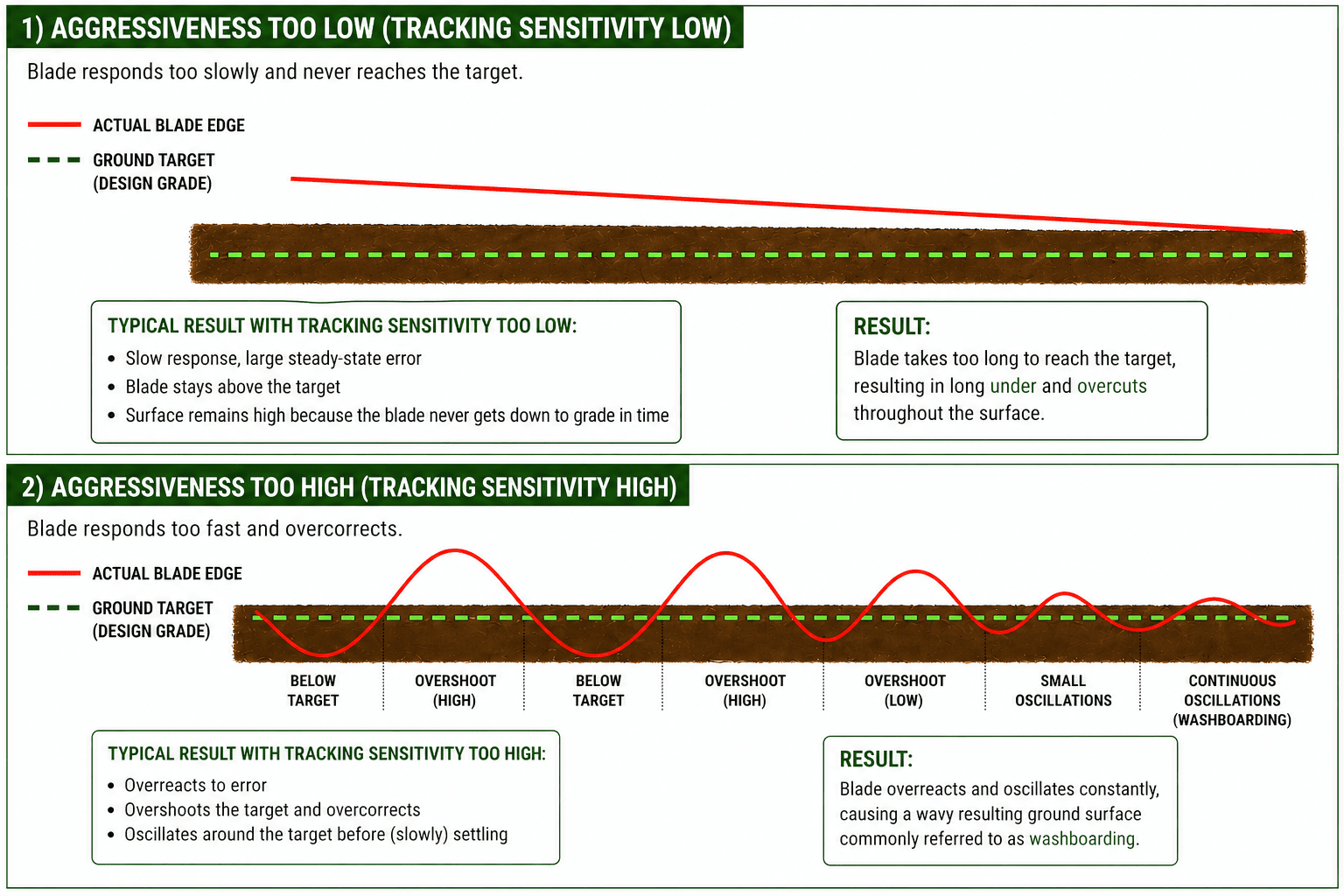
Important ECU status information is displayed at the top left to help identify any configuration or calibration issues before or during tuning. Tracking Sensitivity sets the aggressiveness of automatic control when tracking close to the target. At the right side, the amount of error and commanded % can be visually monitored in real time once engaged, and control performance is indicated by Performance (DPF).

Begin moving at a low speed, above 0.5km/h and enable any detent or limit switches allowing automatic control of tractor valves if required. Fully raise the implement/blade to maximum height.
Engage automatic control with the Arm/Engage switch while carefully observing the implement. Level COMMAND will target the height of the plane, and the implement should begin to acquire and lower to the target height. Once within tracking range, the implement will begin tracking and maintaining the target automatically.
Tracking Sensitivity sets the overall aggressiveness of control and should be set to minimise control error while implementing. Performance (DPF) indicates how well the implement is matching with the target. A DPF value of 0 represents perfect 1:1 control of the blade position at all times. As the DPF value increases, the indicated control performance is worse.
If the blade is raising/lowering or tilting back and forth quickly or erratically, reduce the Tracking Sensitivity by a larger amount like 10 and check whether this improves the performance.
If the blade is lagging behind the target and the error chevron isn't reaching zero, increase the Tracking Sensitivity by a larger amount like 10 and check whether this improves the performance.