Quick Start Guide
Start!
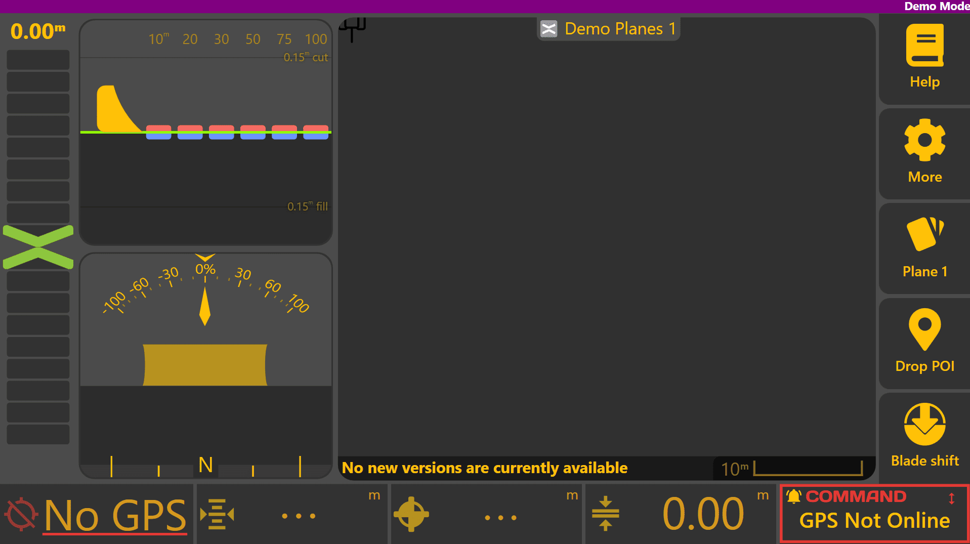
When Level COMMAND is first started, you'll be greeted by the apply page below:
Once all hardware components have been fitted, the COMMAND ECU needs to be set up for the correct configuration to operate Level COMMAND.
COMMAND ECU Quick Setup
For more detailed information on COMMAND hardware such as the ECU or harnessing, please refer to the COMMAND Manual.
Machine
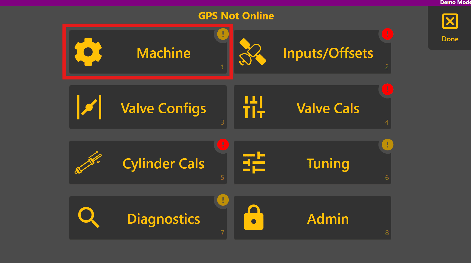
Select the Machine page:
If the Comms tab appears along with "Unable to connect/authenticate to the COMMAND ECU. Confirm ECU power and harnessing", begin troubleshooting harnessing and cable connections to ensure the ECU is powered and serial cable is connected to the tablet PC. If the Profile tabs appears then the ECU has been detected.
Select the appropriate profile for the tractor/implement:

Enter the implement blade width, measured along the cutting edge in the Blade Width field:

Inputs / Offsets
Press Back and then select the Inputs/Offsets Page:

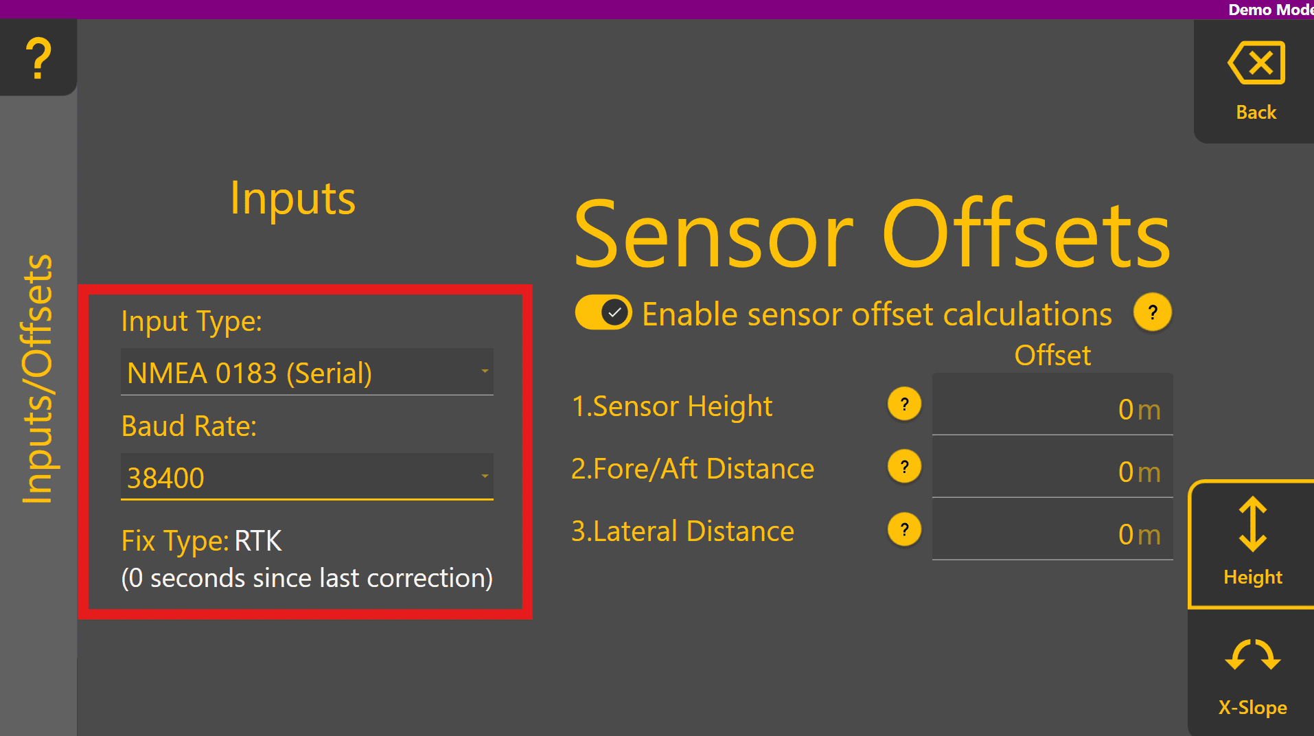
For height-only machine profiles, this page only has one tab for Height. Other profiles like Height & XSlope will display a tab for each function in the bottom right corner. Select the desired height Input type and Baud rate if using NMEA 0183 (we recommend 38400, but this must be configured at both Level COMMAND AND the receiver itself).
If position data is available from the selected GNSS receiver, the Fix Type should change. Note that fix type MUST be RTK for automatic implement control.
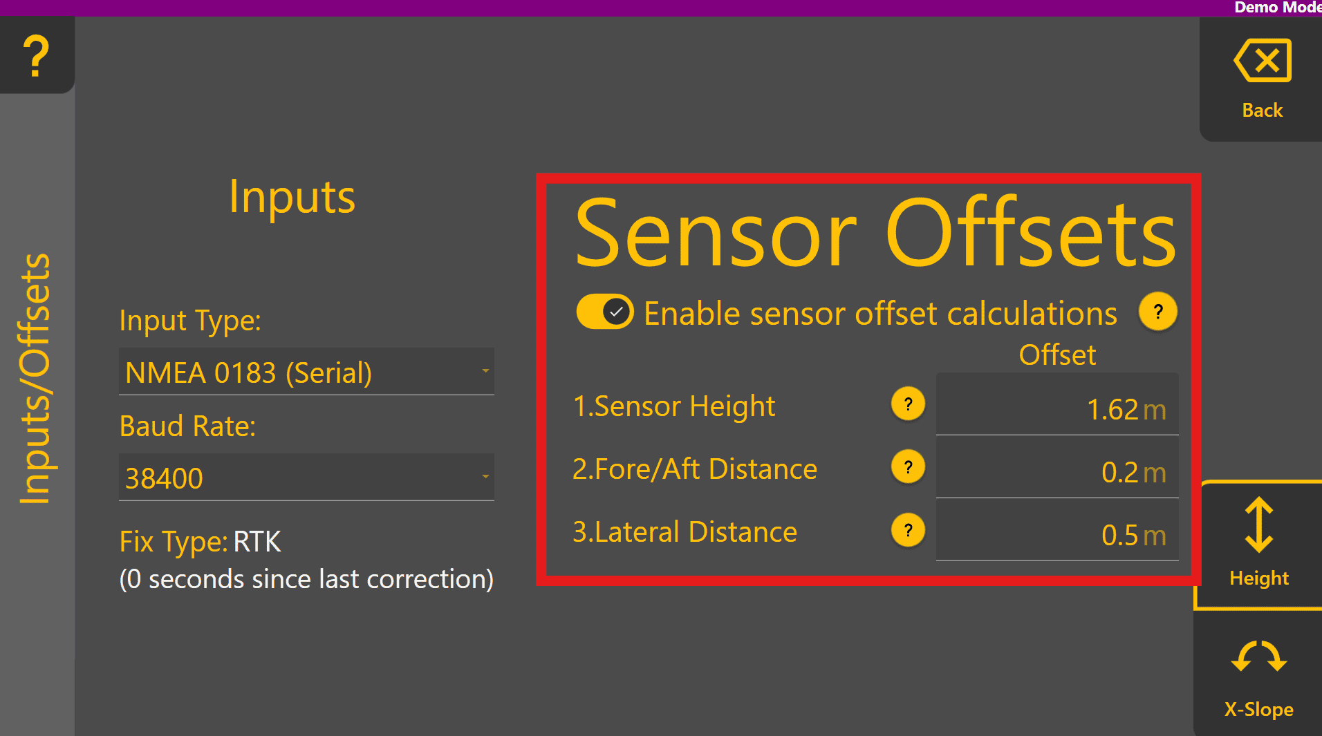
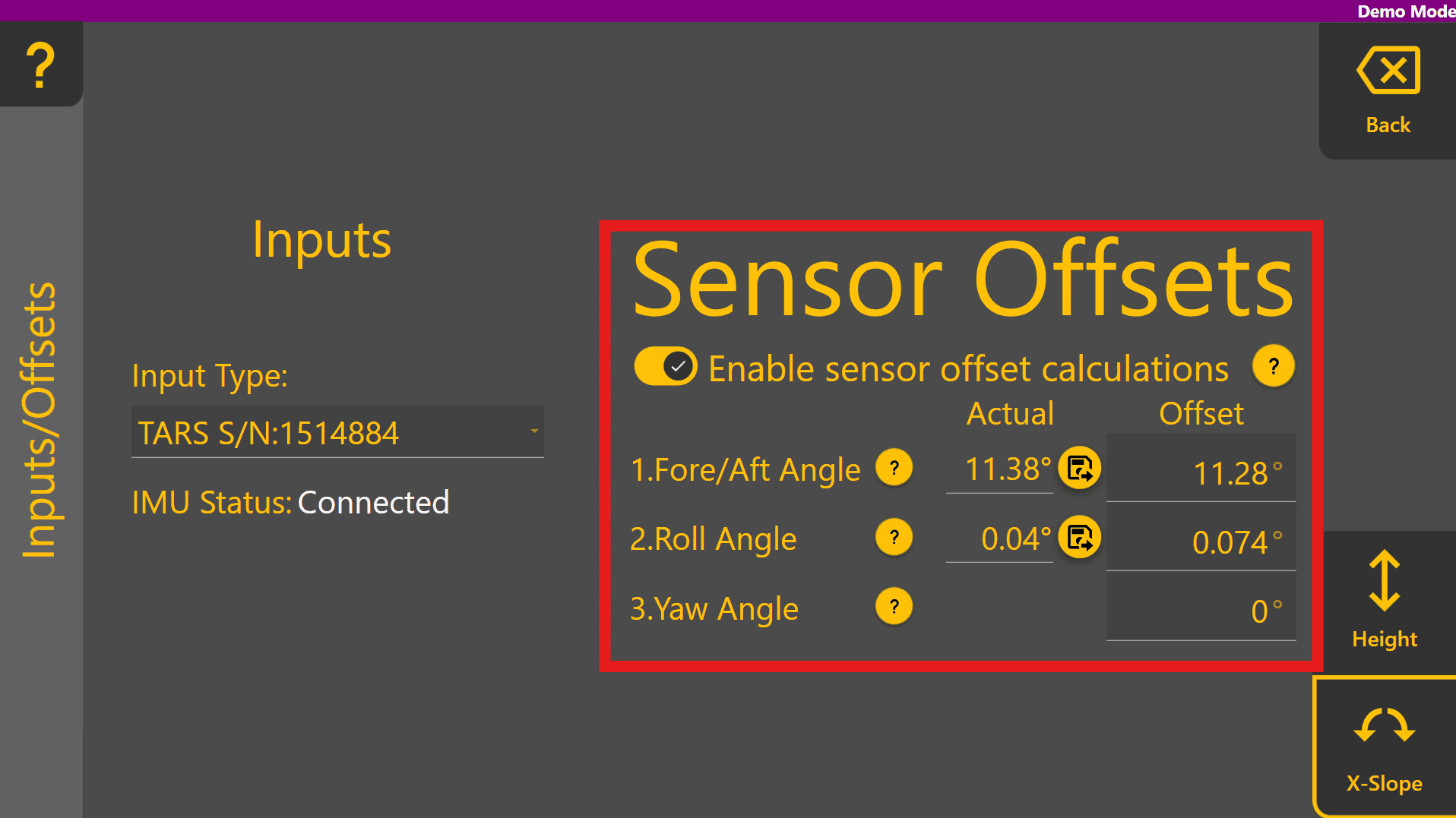
Enable sensor offset calculations using the toggle and then measure and enter each of the Height function offsets - tap the ? for more info on each offset:
If using the Height & XSlope profile, move to the X-Slope tab at the bottom right, then select the desired IMU sensor under Input Type:
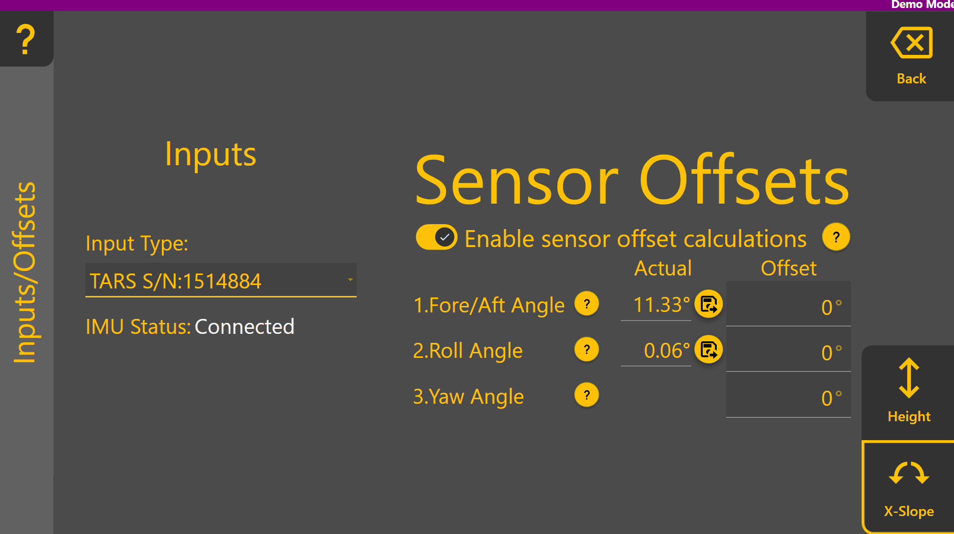
Level the implement blade using a spirit level or similar device to ensure the tilt angle is 0 degrees. Press the set buttons next to Actual Fore/Aft Angle and Actual Roll Angle to set the pitch and roll offsets for the IMU. This calibrates the IMU sensor's mounting angle within the Level COMMAND.
Valve Configs
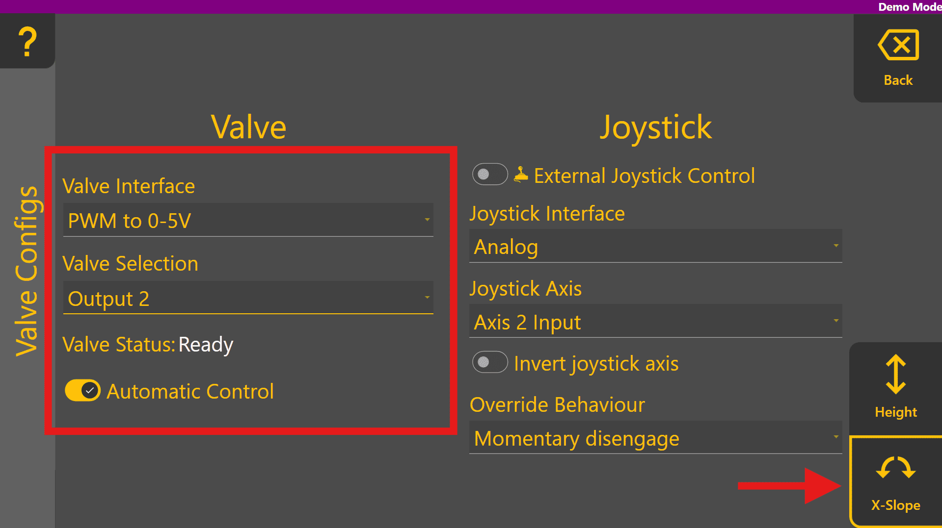
Press the Back button and then select the Valve Configs Page. Select the desired valve interface depending on the tractor or external hydraulics and select the appropriate valve for that function.
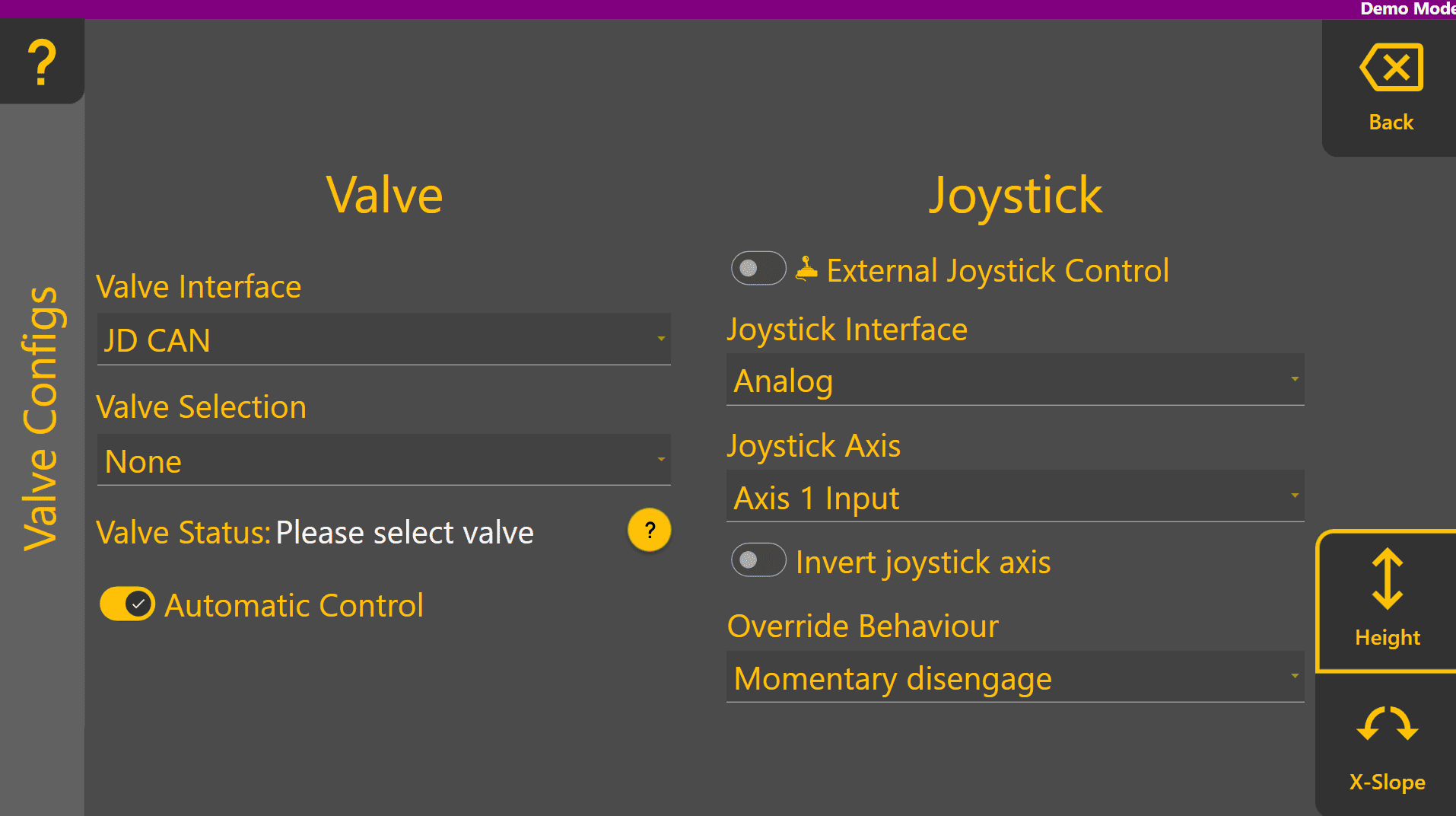
IF "SYSTEM NOT ARMED" is displayed, turn the arm/engage switch off and then back on to arm the system. If the valve status is "Ready", the valve is likely configured correctly but will need to be tested in calibration to be sure.

Do the same for the X-Slope function by swapping tabs and selecting the correct Valve Interface option and Valve Selection. If using Height only, skip this step.
Valve Cals
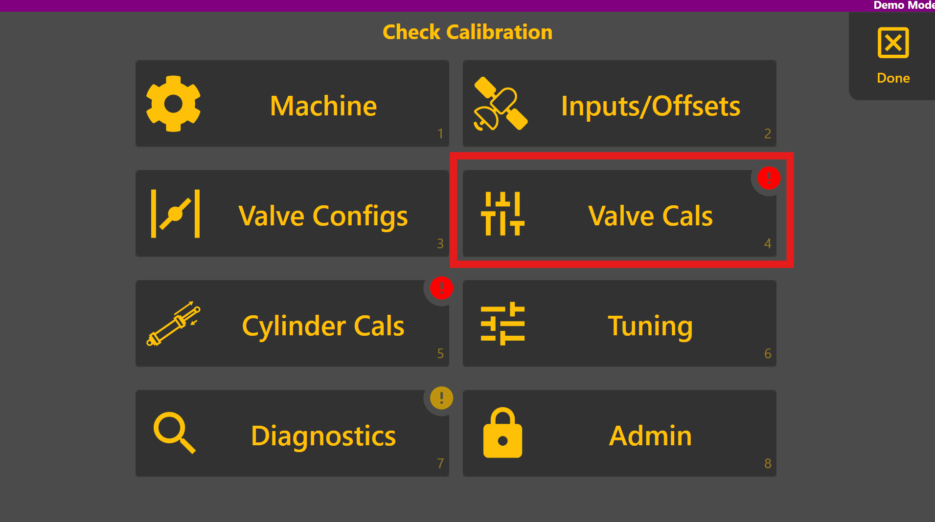
Now that the valves have been selected, calibration of each function can be performed. Press Back and select the Valve Cals page:
For each of the function tabs present at the bottom right, the minimum and maximum calibrations for each direction need to be set. Calibration may be performed while stationary (the operator must hold the engage button down for the valve signal to trigger) or while moving, but no faster than 5 km/h. For more detailed information on calibration, refer to the Settings section in this manual.
To perform calibration begin with the Min Up threshold. A starting point of 20% is recommended for the minimum thresholds and leaving the maximum thresholds on 100% generally, however these can be reduced if the implement moves too quickly at full hydraulic flow. Set the minimum Up % to 20 and press the "TEST" button on the right. Once the pop up window is displayed, holding the engage button will activate the up direction at 20% intensity - ensure that it's safe to move the implement before holding the engage button.
Set the min % such that the implement is just beginning to move upward at a very slow speed.
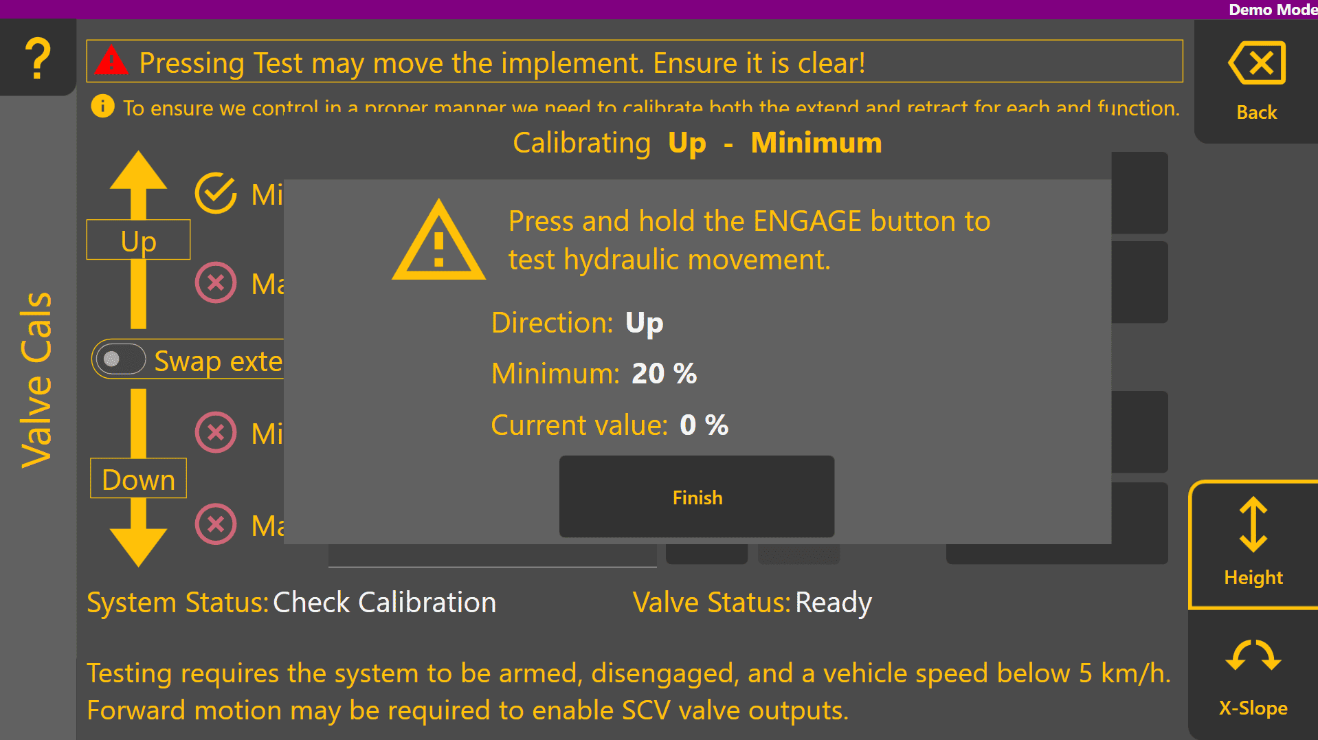
If the implement moves downward instead of upward, press the swap extend/retract toggle to reverse the direction of movement.
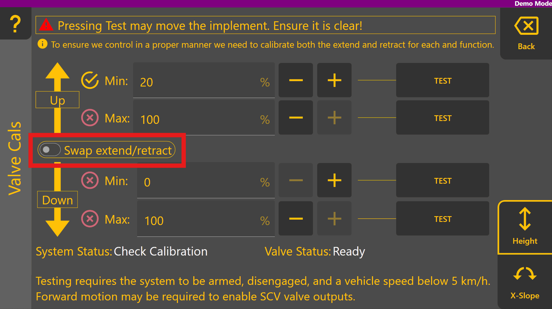
Test Max and ensure that the implement does not move too quickly for safety reasons - if it does, reduce Max until the implement moves at an appropriate maximum speed upward.
Repeat the process for Down Min and Max, setting the percentage needed for minimum and maximum downward speed. Once each of the thresholds for a function have all been tested, all four parameters will be ticked instead of crossed.
Ticks in this instance simply mean that the test button was pressed and do not indicate a correctly calibrated function.
Perform the same calibration routine for the X-Slope function if present, otherwise skip this step:

Once each function has been fully calibrated, the System Status will now change to Ready to Engage indicating that automatic control can now be engaged.
Press the Back button to return to the COMMAND Settings overview page.
Checking Control Performance
To check whether control performance is initially acceptable, there are two options:
- Load a suitable design file OR
- Create a basic plane
Loading a Design File
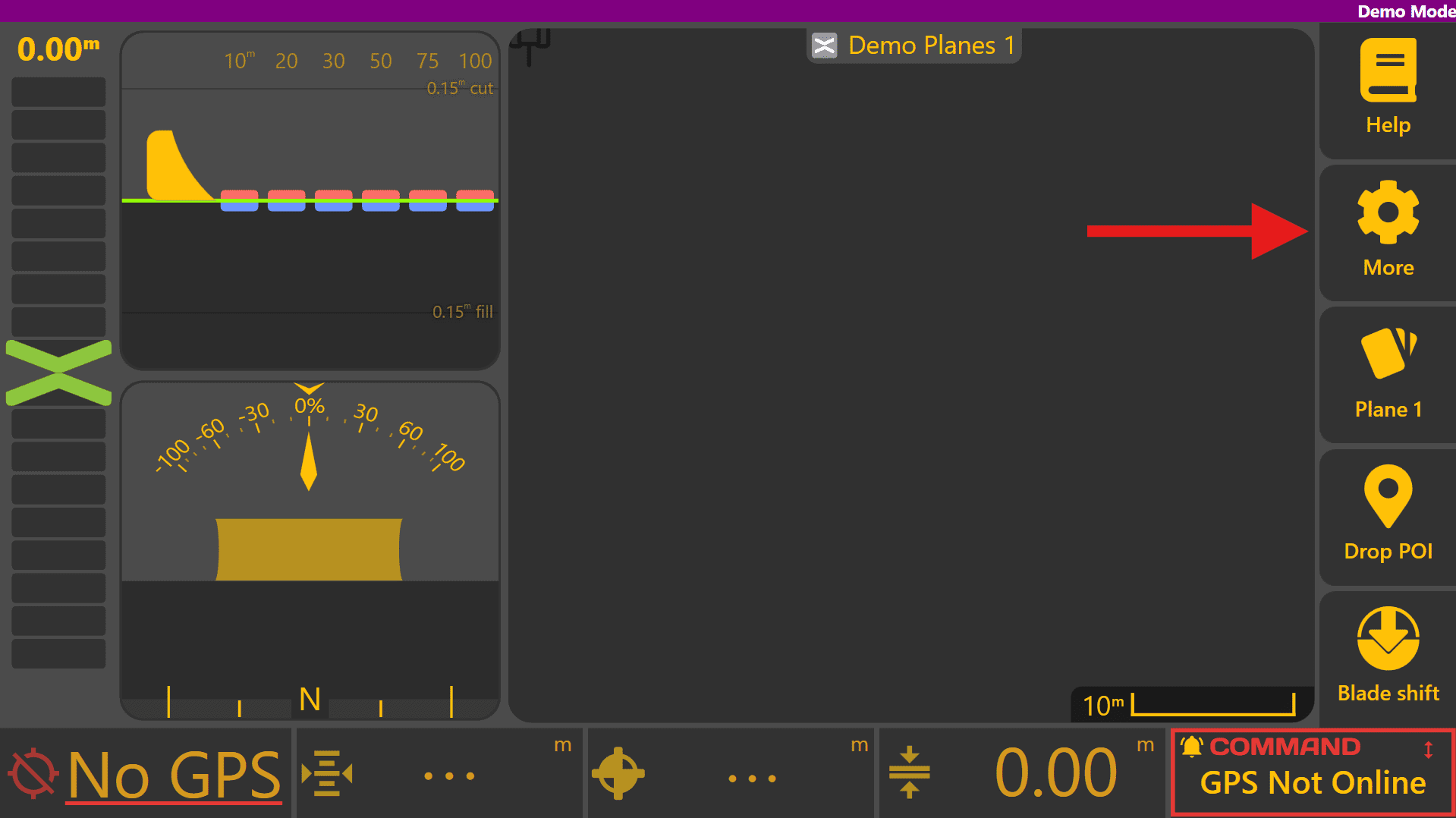
To load a design file, press Done at the top-right to return to the Level COMMAND apply page, then press More > Change Project:
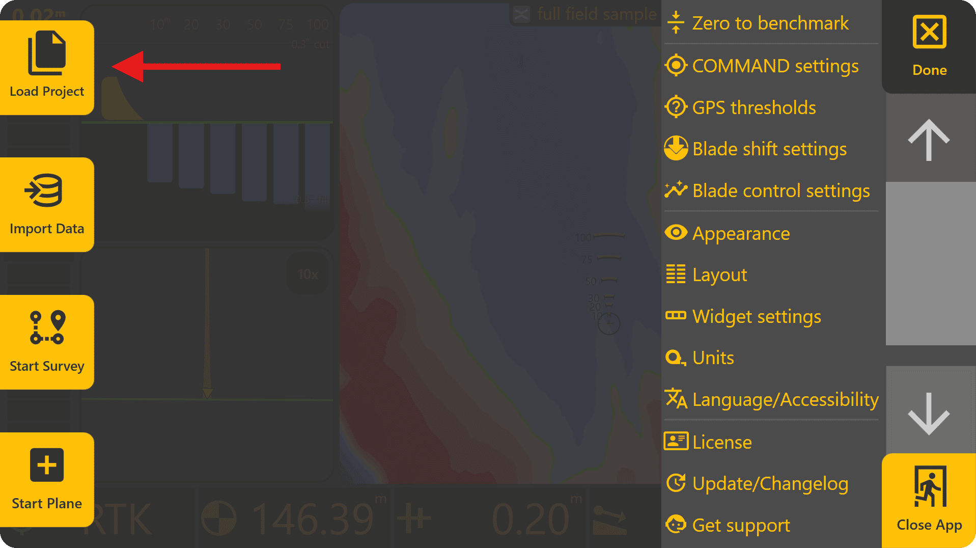
If loading an existing Plane Project, select it from the list and press Load Selected. If loading a .tci or .gps design file, press To Import.
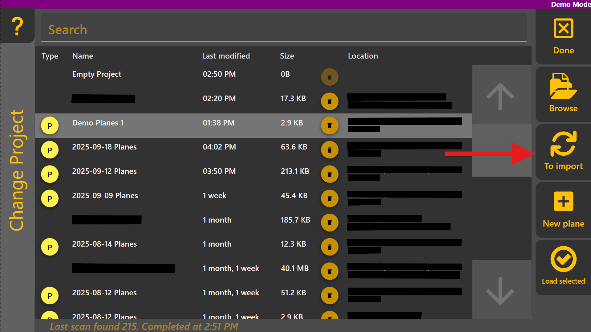
Select the design file from the list and press Load Selected.

Creating a Basic Plane
To create a basic plane, begin by pressing More > Start Plane, then name the plane project and choose where it should be saved. Begin designing a plane by pressing Create Plane at the bottom right (or alternatively the Planes button and then select one of the Plane slots).
Set the height of the implement cutting edge about 20cm / 0.5ft above the ground surface to begin with and set the origin. If working on a steeply sloped area, you may want to "drive-out" the primary slope using the plane tool and can then test control above the surface without risking implement contact with the ground.
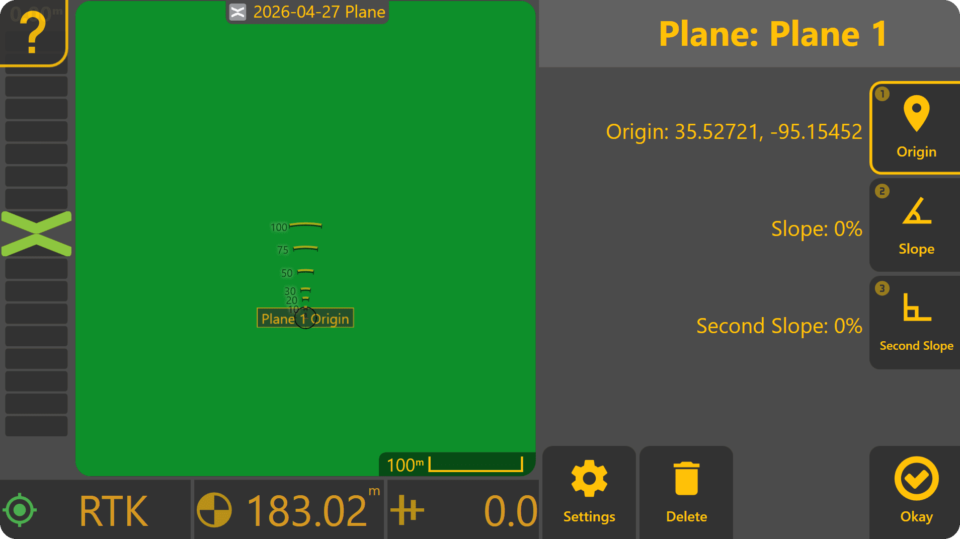
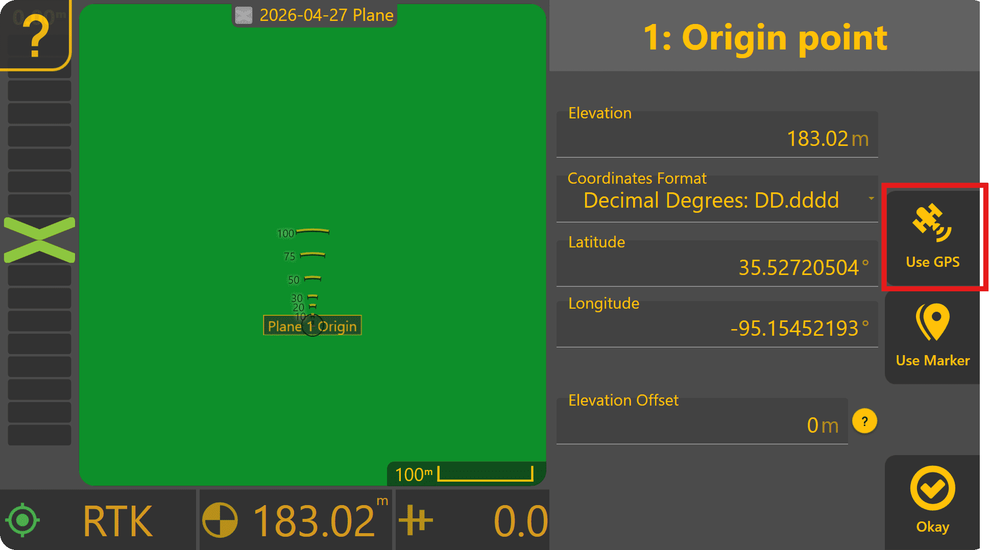
Press Origin to edit the plane's origin point. Press Use GPS to set the plane origin to the current implement height.
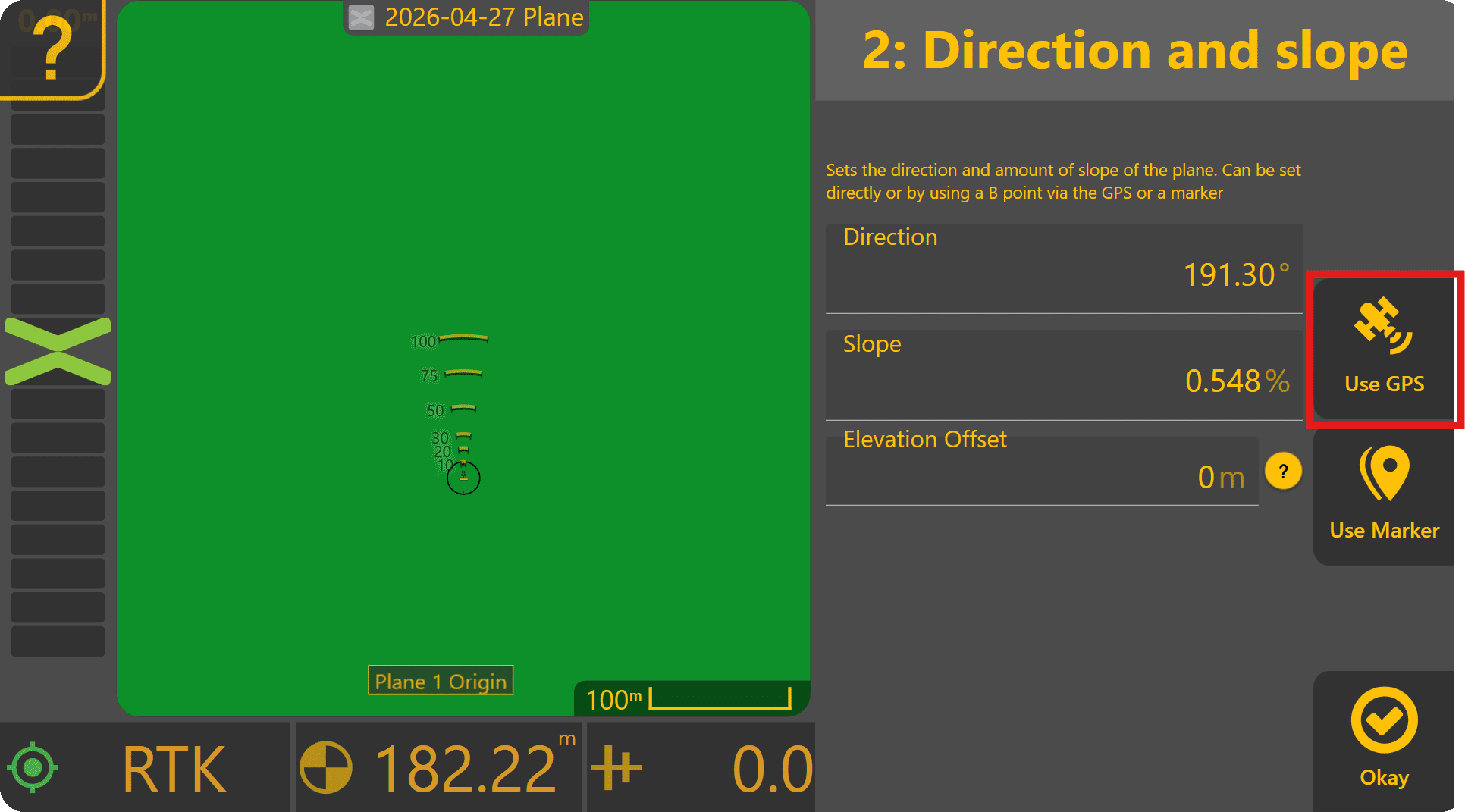
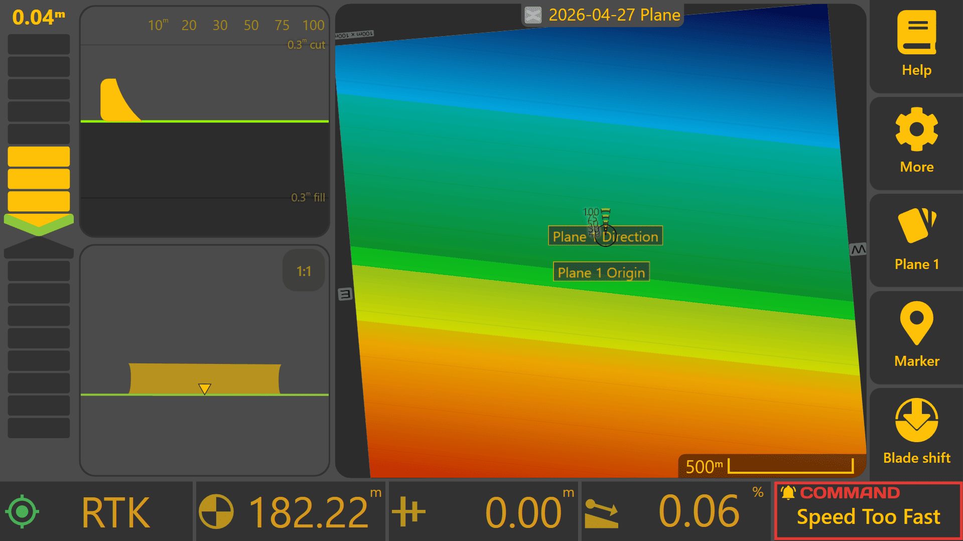
Press Okay - a flat plane has now been created at the origin point. If testing on a slope, press Slope, then drive from the origin point to the lowest point of the surface. Press Use GPS to set the slope point to the current implement height - the plane should now have a new slope angle and direction.
Preliminary Tuning - Air-levelling / Air-grading
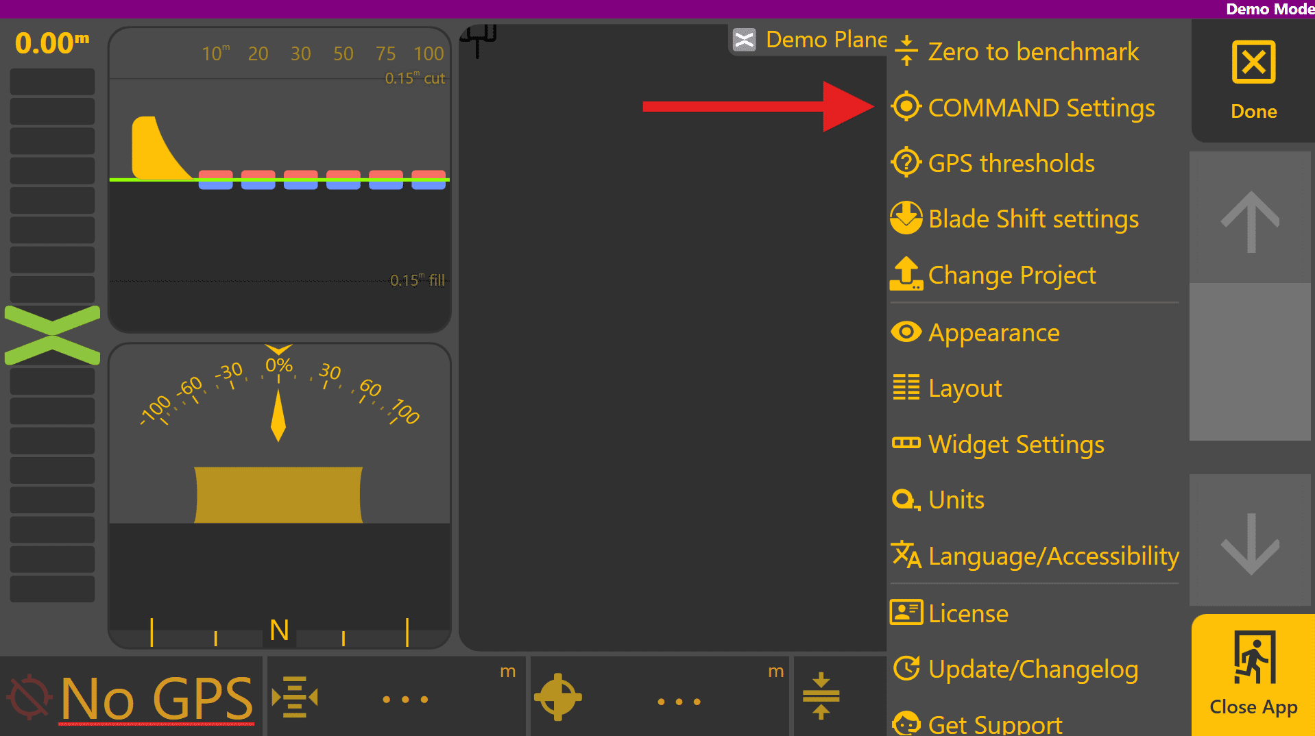
Press More > COMMAND Settings > Tuning.
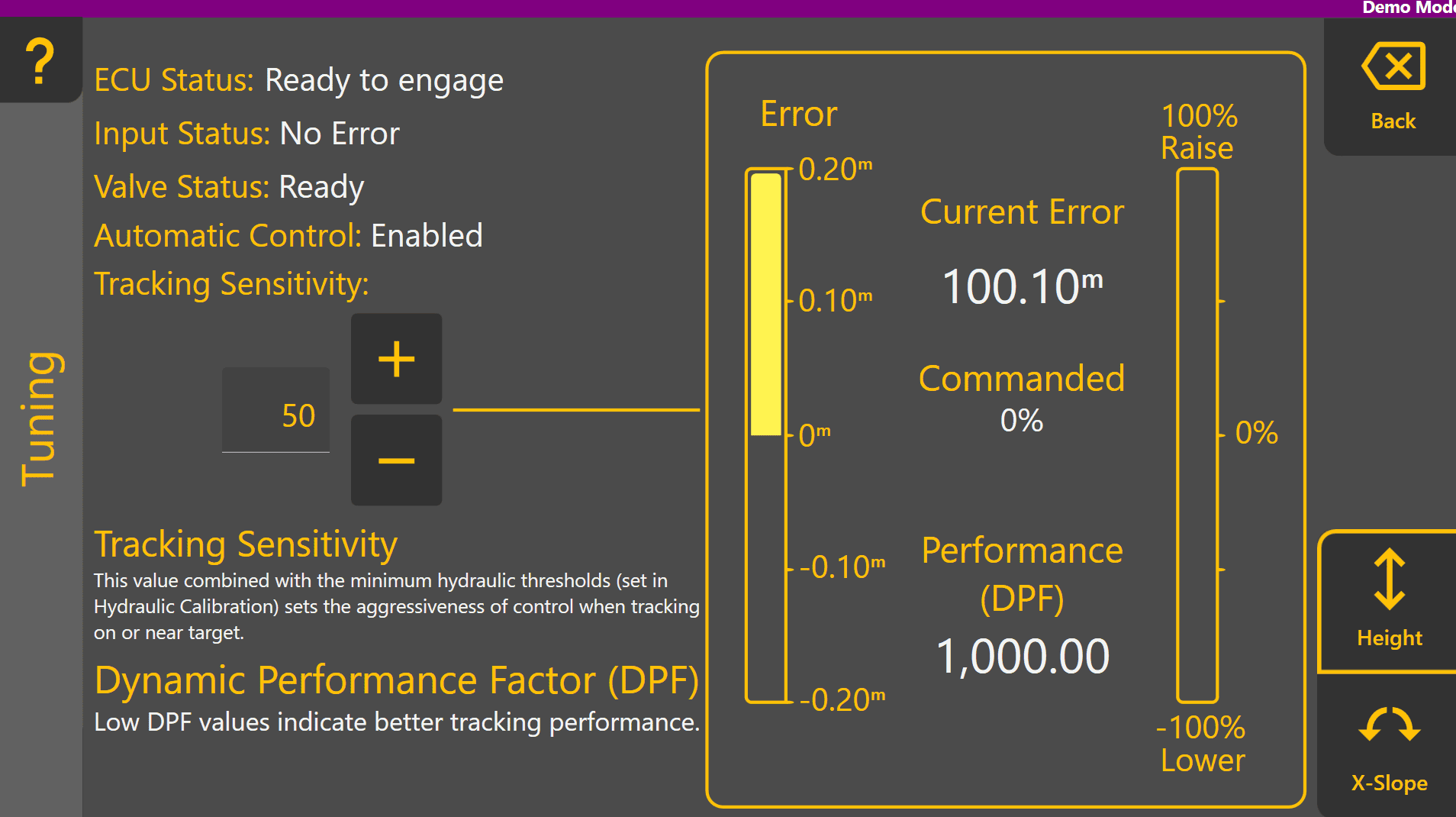
Important ECU status information is displayed at the top left to help identify any configuration or calibration issues before or during tuning. Tracking Sensitivity sets the aggressiveness of automatic control when tracking close to the target. At the right side, the amount of error and commanded % can be visually monitored in real time once engaged, and control performance is indicated by Performance (DPF).

Begin moving at a low speed, above 0.5km/h and enable any detent or limit switches allowing automatic control of tractor valves if required. Fully raise the implement/blade to maximum height.
Engage automatic control with the Arm/Engage switch while carefully observing the implement. Level COMMAND will target the height of the plane, and the implement should begin to acquire and lower to the target height. Once within tracking range, the implement will begin tracking and maintaining the target automatically.
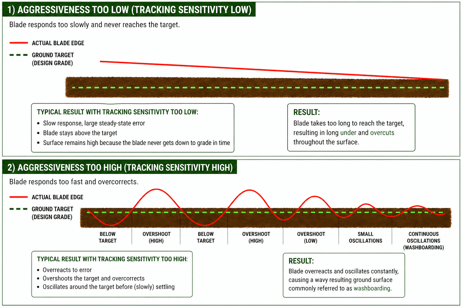
Tracking Sensitivity sets the overall aggressiveness of control and should be set to minimise control error while implementing. Performance (DPF) indicates how well the implement is matching with the target. A DPF value of 0 represents perfect 1:1 control of the blade position at all times. As the DPF value increases, the indicated control performance is worse.
If the blade is raising/lowering or tilting back and forth quickly or erratically, reduce the Tracking Sensitivity by a larger amount like 10 and check whether this improves the performance.
If the blade is lagging behind the target and the error chevron isn't reaching zero, increase the Tracking Sensitivity by a larger amount like 10 and check whether this improves the performance.