
7.6 | External Proportional Solenoid Valves
Applicable to: Implements fitted with compatible external proportional solenoid valves, typically mounted on the scraper or implement.
IMPORTANT: Confirm that the external valve’s electrical requirements are compatible with COMMAND. The ECU supports a maximum coil current of 2 A. If a coil would draw more than 2 A at full output (100% PWM), reduce the corresponding Max % setting in Level COMMAND before operating the valve. This limits the maximum output to prevent an overcurrent fault.
Connection Method
COMMAND directly controls the valve solenoids using current-controlled PWM outputs. The T3H-V002 valve extension connects to the T3H-C002 ECU breakout harness and provides a 6 m extension to the implement-mounted valves.
The T3H-V003 — Valve Adapter – Prop. Solenoid (2-way DT) connects the extension to valves fitted with compatible 2-pin Deutsch connections.
NOTE: For valves using other connector types, such as Hirschmann, the dealer or installer must provide a suitable adapter. T3RRA currently supplies the 2-pin Deutsch valve adapter only. Any alternative adapter must maintain the correct circuit connections and comply with the valve manufacturer’s polarity requirements.
Installation Steps
1. Complete the machine preparation steps in Section 5.1 and isolate the tractor electrical supply.
2. Connect the T3H-V002 valve extension to the valve output connector on the T3H-C002 ECU breakout harness.
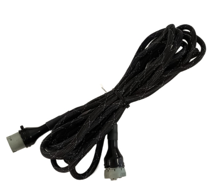
3. Route the extension to the external valve block. Allow sufficient slack for tractor articulation and implement movement, and secure the harness clear of moving parts, hot surfaces and pinch points.
4. Connect the T3H-V003 valve adapter, or suitable alternative adapter, to the implement end of the T3H-V002 extension.
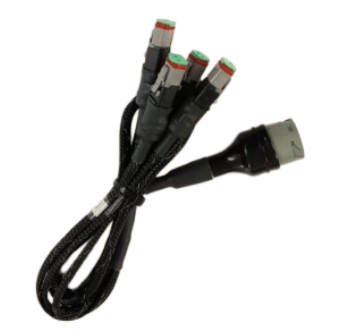
5. Connect the adapter’s solenoid plugs to the appropriate valve coils for each controlled function, such as height and cross-slope. Identify the raise/lower or tilt directions for verification during setup.
6. Secure the connections and protect any unused connectors against moisture and dirt.
7. Keep COMMAND disarmed and restore the electrical supply.
Valve Configuration
Confirm that the valve’s electrical requirements are compatible with COMMAND before operating the outputs. Refer to Section 2.4 for proportional solenoid compatibility.
In Level COMMAND:
- Select Proportional Solenoid as the valve interface.
- Assign the required valve outputs to each controlled function.
- Configure the PWM frequency and operating current limits to suit the valve manufacturer’s specifications.
- Verify that each function moves in the intended direction, then complete valve threshold and cylinder calibration.
For detailed configuration and calibration instructions, refer to the Level COMMAND Manual.
NOTE: The external valve block must have the hydraulic supply and return connections required by the implement manufacturer. Configure any tractor remote supplying the valve block according to those instructions.
Operation Notes
If manual control is not already provided, install a compatible joystick as described in Section 6.3.
COMMAND must be armed for a connected joystick to operate the valve outputs. Use the COMMAND Arm/Engage switch to arm the system and engage automatic control.
Joystick movement can disengage automatic control or temporarily override it, depending on the selected joystick configuration. Confirm the configured behaviour during commissioning and demonstrate it to the operator.
IMPORTANT: To stop automatic control, press the momentary side of the COMMAND Arm/Engage switch. Move the switch to OFF to disarm COMMAND and disable its hydraulic control outputs. Disarming also disables valve operation from a COMMAND-connected joystick.