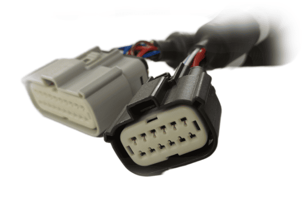
ECU Installation
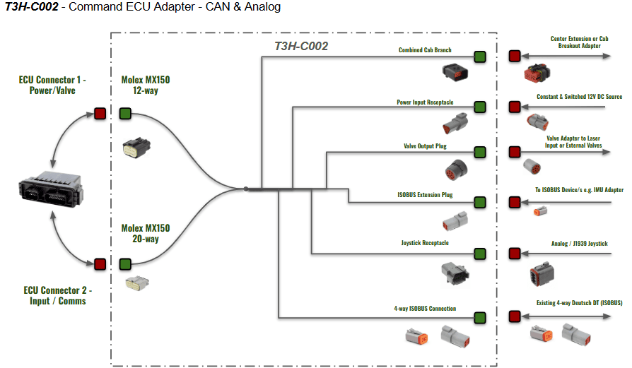
ECU Connections Overview
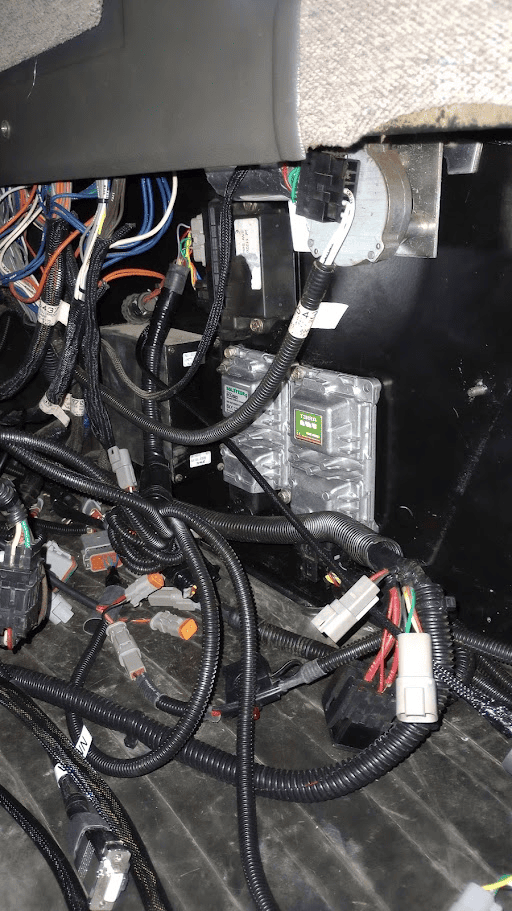
Option 1: In-cab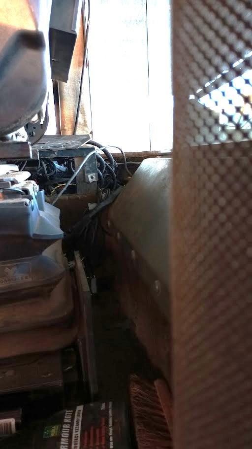
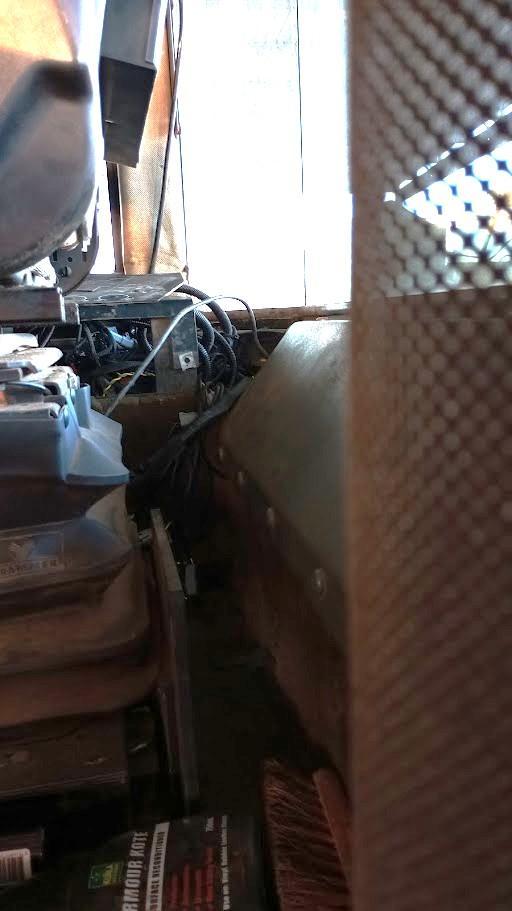
Mounting in the cab of the tractor is the preferred option, as it best protects the ECU and harnessing from the elements. Mounting the ECU in-cab is best suited to tractors with paneling, compartments or normally covered cab walls with enough room to mount the ECU.
Being mounted in cab will provide access to the following for the T3H-C002 ECU breakout harness:
- Power via convenience plug or power strip
- Arm/Engage Switch
- Tablet
- 4-way ISOBUS connection from Greenstar ISO harness
- Diagnostic ports for tractor CAN access
- Joystick
- Valve output connections to JD legacy inputs or Case EHR inputs
Cabling will need to be run outside of the cab if:
- Proportional solenoid or Danfoss PVE valve cabling must be run out to an external valve block
Option 2: Rear-panel 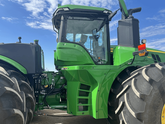
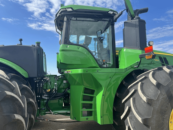
In situations where the cab doesn't have enough suitable space for mounting the ECU and neatening the harnessing, the ECU can be mounted at the back of the tractor
Option 3: Rear ISOBUS 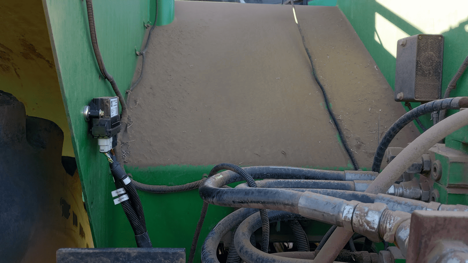
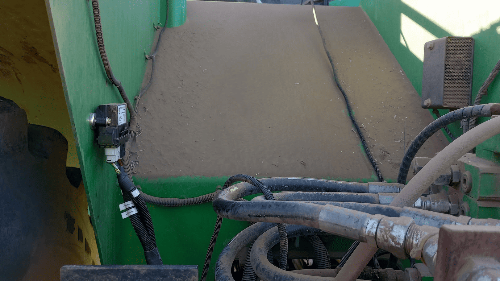
Recommended in these situations
Mechanical
Mounting
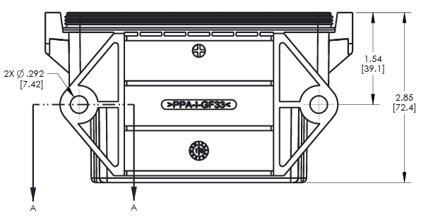
Information & ECU Dimensions
Magnets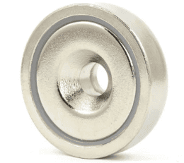
Mounting with strong neodymium magnets can provide a quick and robust method of mounting the COMMAND ECU.
Neodymium magnets with a countersunk centre hole of 7mm diameter along with 7mm fasteners should be used.
Rivnuts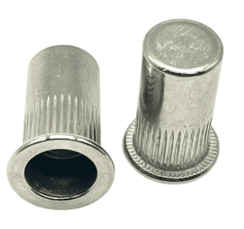
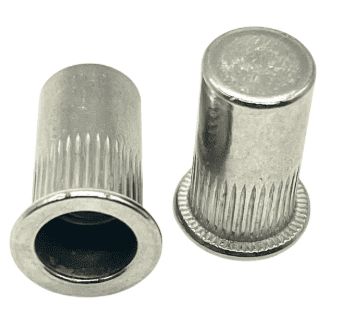
Mounting with Rivnuts is another effective way of securing the ECU to the inner or outer wall of the tractor.
Care should be taken to drill an appropriately sized hole of the Rivnut, then use the expansion tool and fasten the ECU securely.
Mounting orientation
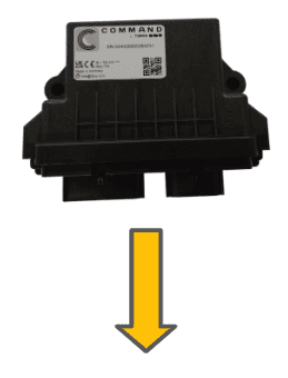
The COMMAND ECU should be mounted with the electrical connectors facing downward. Doing so will reduce any possibility of ingress by moisture or dirt. Do not mount the ECU with the connectors facing upward or to the side as moisture or dirt may accumulate and cause corrosion and/or connection issues.