# 9 | Implementing
# 9.1 | Starting Implementation
## T3RRA Software implementation startup instructions for UCC1
1. Drive to a zero cut/fill area and place the scraper cutting edge on the ground. Drop a marker for future reference. When zeroing on drains, ensure that the position indicator is on the drain surface.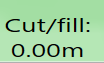 
2. Select **Set Zero** to zero the T3RRA Cutta, choose **Zero against the surface**, then select **OK**. 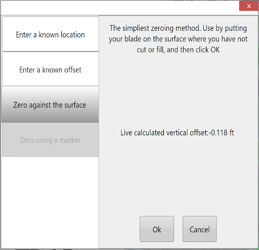
3. Select **Start** in your T3RRA software to begin implementation, then press **Set Offset – Zero Error** on the iGrade\*. 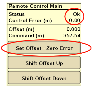
4. Place the applicable SCV’s in the **Detent** position, **not float**, to set iGrade™ to automatic control.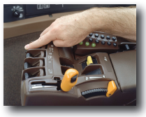
## T3RRA Software implementation startup instructions for UCC2
1. Drive to a zero cut/fill area and place the scraper cutting edge on the ground. Drop a marker for future reference. When zeroing on drains, ensure that the position indicator is on the drain surface.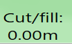 
2. Select **Set Zero** to zero the T3RRA, choose **Zero against the surface**, then select **OK**. 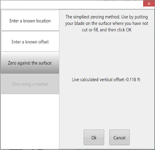
3. Select **Start** to start sending commands to iGrade.
4. Verify that **Elevation Error** remains **0.00**. If not, press the **Set Zero Error Button** on the iGrade\*.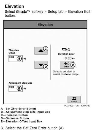
## Notes
- After placing the scraper cutting edge on the ground, verify that the selected SCV(s) (1 and/or 3) are in **Auto**.
- Manually adjusting blade height with SCV disables Automatic Control. Returning SCV to detent automates control.
# 9.2 | Understanding how "As-applied" works
Earthmoving has three states:
1. What you started with.
2. What you intended to do.
3. What you actually did.
The original field surface is your starting point; the intended result is a field surface that matches your design. An “As-applied” (or “As-built”) map records what you actually did.
The “As-applied” map continually records both completed work and work still to be done. At the start of a job, no work has been done, so the map is exactly the same as the original surface. At the end, the field surface will match the design surface, and the “As-applied” map should match the design map. During the job, both the map and the actual field surface will be somewhere between the original and design surfaces.
The software constantly tracks the blade and updates the “As-applied” map as cuts and fills occur. Initially, it knows only that the field matches the original surface map. When the blade goes below that surface, the software records a cut and updates the “As-applied” map, which then differs from the original surface map. As the blade cuts progressively lower, the map continues to update.
Cut measurements tend to be quite accurate: when the blade goes below a previous cut, the new cut level must be the new true earth surface. Fill measurements are more difficult. A blade above the surface does not necessarily mean that dirt is leaving the scraper pan; the implement may simply be travelling between locations. The software accounts for whether the design calls for a cut or fill and for the blade’s position relative to the design height, but fill measurements *will not be perfect.*
T3RRA software tracks activity over time, continuously surveying the current state of the job surface.
**Important:** T3RRA software cannot know what other equipment is doing. If another machine operates in the same work area as you, your “As-applied” map will not be accurate. You can track only your own activities.
**Important:** T3RRA software cannot know what work was done before you arrived. If the original surface map does not represent the terrain on arrival because another operator has already completed part of the job, the “As-applied” map will not be accurate. To make it accurate, drive over the entire surface again to calibrate the as-applied map. **It only knows what it has surveyed.**
# 9.3 | Understanding the relationship between the "As-applied" surface and the Dynamic Blade Limit.
The Dynamic Blade Limit depends entirely on “As-applied” functionality. If “As-applied” is not activated or is not working properly, the blade limit will not work. To distinguish this from “Static Blade Limit”, see that section in the [Limits Tab](https://t3rra-help.freshdesk.com/en/support/solutions/articles/51000328671-limits-tab).
GPS tells T3RRA software where the cutting edge currently is, and the software also knows the original surface. With “As-applied” functionality turned on, it tracks changes to the current (“As-applied”) surface, so it knows the actual surface height wherever you are in the field. It uses this information to limit the cutting edge’s target elevation to a certain amount below or above the “As-applied” surface.
If T3RRA software loses track of the current surface, the Blade Limit will no longer work. For example, on an untouched part of a field requiring 6 inches of cut, a 2 inch blade limit means you would expect 3 passes to reach final grade. If another operator has already removed the top 4 inches, you may expect to finish in one pass. However, T3RRA software does not know that those top 4 inches are gone. On your first pass, the blade limit will keep the cutting edge two inches above the current surface; on the second pass, it will only skim the surface. The blade will enter the ground only on the 3rd pass.
T3RRA software surveys as it goes, tracking blade heights to determine the surface. Any change to the surface since the software last surveyed it will cause Blade Limit errors. Blade Limit guides the blade relative to where it *thinks* the dirt surface is, not where it *actually* is. As long as **you alone** change the field, those positions will be the same. If someone else makes changes, that relationship cannot be relied on.
**Do NOT** expect Dynamic Blade Limit to work properly if anyone other than you is working in a field **OR** if anyone else has worked on the job since the original surface was surveyed.