# Surface Tools
# Surface tools overview
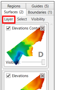When the Surface tab is selected on the right hand side, the relevant tools can be accessed in two different areas. Firstly, on the menu bar (this changes depending on which layer type is selected) and is explained below in Surface design tools and secondly, in the Layer menu on the selected tab and is explained in Surface tools - Layer Menu.
# Create a surface design for the selected area
This tool is the primary method for creating field designs. This tool opens a window with several design options to choose from: ‘Plane of Best Fit’, ‘Directional Best Fit Design’, ‘Multifit Design’, ‘Omni-fit Design’, ‘Surface Smoothing Design’, and Duplicating the current surface.
All the options available in the create a surface design tool can be limited to the boundary, all region parts, or an individual region.
The additional options that are available in most surface design options are ‘Shift design vertically’, ‘Cut/fill ratio’, and ‘Import/Export’.
‘Shift design vertically’ will move the design layer vertically according to the value that is input. A negative value should be used to move the design down.
‘Compaction ratio’ will adjust the design to accomodate a specific cut /fill ratio.
‘Import/Export’ will set the design to ensure a certain amount of soil is present to import or export. Importing and exporting volumes cannot be set at the same time, but you can set a compaction ratio. When you specify an import/export volume, please also indicate whether the imported/exported soil is already compacted with the check box that appears on the right.
Plane of Best Fit
A ‘Plane of Best Fit’ will attempt to create a flat plane on the elevation surface that flows with the field’s natural slope direction.
The ‘Plane of Best Fit’ will apply both a primary slope and a secondary slope. The secondary slope will always be at 90o to the primary. The direction of the slope is shown next to the slope and the severity of the slope is displayed on the right side of the window.
There are 3 design options for creating a ‘Plane of Best Fit’.
‘Shift design vertically’ changes how far above or below the design is made from the surface.
‘Cut/Fill Ratio’ allows you to set the ratio of the Cut and Fill to what is appropriate for your soil properties.
‘Import/Export’ allows you to set how much soil needs to be brought in from another location or how much needs to be taken from this location to be used elsewhere.
The Design details drop down will display information about the design such as the total area, total area cut, total area filled and volumes.
Show cut/fill surface, this button is a toggle which will only show the Cut/Fill while it is selected.
Directional Best Fit Design
‘Directional Best Fit’ creates a straight plane and allows you to completely control the direction of the field slope.
When using ‘Directional Best Fit’ a blue line will appear on the field. This line is used to control the direction of the plane.
‘Auto-calculate best fit’ will have the tool automatically generate the most effective plane of best fit in the set directions.
‘min(x)% to max(X)%’ will tell the tool to generate the most effective plane of best fit following the set direction and within the set parameters.
‘Set % slope’ will create a plane of best fit at the set slope value in the set direction.
‘Primary (X) Direction’ displays the current direction of the line and allows you to manually set the slope direction without using the blue line.
The field design is also able to be split into parallel strips. These strips will flow in the direction set by the primary slope.
There are also options such as shifting the design vertically by a set distance, set a Cut/Fill ratio and setting the Import/Export for soil that may be brought in from another location.
Multi-Fit Design
Using Multi-Fit design will create a design for the field in the work area that follows the movements of the surface more closely in an attempt to reduce the amount of earth moved.
The desired direction can be set using the ‘Direction (degrees)’ option which will shift the direction of the line.
A Multi-Fit design is made by breaking the surface into strips and cutting those strips into smaller sections. The algorithm works its way along each strip, balancing the dirt back towards the start of the strip as it makes its way down each strip.
‘Plane strip width’ controls how wide the strips are that the field is broken into.
‘Section length’ controls how long each segment is along each strip.
The smaller the value set in these options, the smoother the design will be, but the longer it will take to calculate.
‘Start lock’ and ‘End lock’ are used to tell Multi-Fit to match the elevations at the start or the end of each strip.
Setting Start lock to ‘at or below’ will help ensure that the Multi-Fit strips drain from head ditches.
An End lock can help ensure drainage into tail ditches.
Note: If you set these locks, sometimes a strip may not be able to satisfy the lock. In this case, you may change the strip width and try again, or use an unlocked Multi-Fit Design in the places that had troubles.
‘Set the slope range’ creates a minimum and maximum grade that you want to be present in the design. Multi-Fit will attempt to follow the natural flow of the field within the set range.
‘Calculate only cuts’ this option will tell the tool to ignore any section that requires a fill. The resulting surface will be at or below the original surface at all points. This parameter is normally activated in situations where you always want water to flow in the primary direction and do not care what the maximum slope is. It will create a design where obstructions to flow are shaved away and naturally draining sections remain undisturbed. The most usual use case for this option is when ‘flossing’ existing beds in furrow irrigation scenarios (the cut dirt is swept up onto the beds, so fill zones are not required).
‘Perform cross-strip optimization’ tells the tool to tilt the strips in the cross-strip direction to optimize cut and fill. This may not be needed with fields that have a low side slope. This will attempt to tilt the strip sections to match the actual side slope present, up to the maximum slope set for the main direction. Use this parameter in fields that have high side slopes.
‘Target Cut/Fill’ allows you to set the desired cut and fill ratio for the field.
'Perform preliminary side slope adjustment' this option will cause an initial side slope adjustment to occur. It will attempt to ensure that the side slope is no greater than the minimum row slope. Use this parameter if water might have a tendency to run across rows rather than down the rows. It always uses the ‘minimum parameter’ as it’s ‘maximum parameter’.
‘Execute multiple, sequential, directional fits’ is an option to “customize” the land forming design by breaking it down into multiple slope directions. This is for an advanced user with engineering knowledge.
Multi-Fit tends to keep closer to the starting elevation of each strip than the end elevation. If you want the Multi-Fit to keep the end elevation close to the existing level, reverse the direction (add or subtract 180°), and swap your minimum and maximum grades. Additional options include being able to Shift design vertically by a set distance, Cut/Fill allows you to set the cut and fill ratio, and Import/Export which allows you to set the amount of soil that may be brought into or out of the field.
NOTE: Vertical offset relates to the ground, not the orientation of the computer monitor.
Omni-Fit Design
‘Omni-Fit’ is best suited for smaller fields.
‘Omni-Fit’ is the implementation of a Multi-Fit surface with an added secondary slope allowing for further controlled water flow direction.
‘Primary direction’ is used to adjust the main direction you wish the slope to move in.
‘Secondary direction’ will always be at a 90° angle to the ‘Primary direction’.
‘Target Cut/Fill Ratio’ will adjust the design in order to match the cut and fill ratio that you put in this section.
‘Import/Export’ sets the amount of soil that would be brought into and out of the field, this is measured in cubic meters.
‘Limit slope change to at most (%/m)’ is an optional setting, by putting a value in this setting you are able to limit how sharply the field’s slope may change.
Pressing the Question mark button next to this tool will open a graphic calculator making it easier to find the % per unit of measurement.
Primary and Secondary direction slope allows you to set the minimum and maximum grade of slope that can be present in the design. Setting the slope for the secondary direction is an optional setting.
The Following settings are available by clicking on Advanced Options
The ‘Engine’ setting. These are external optimization software engines. COIN-OR Clp will complete the work faster, whereas LP Solve is more robust. If you are having issues with COIN-OR Clp try switching to LP Solve.
The ‘Quality’ option controls the field resolution used by the optimizer. “Draft” is recommended for normal use as it takes far less time to process. “Final” takes significantly longer to process the field data but creates a finer surface, best used to optimize finer details. When you have settings you are happy with in Draft mode, save your work (as a separate file), then you can try running it overnight with Quality set to Final. Be sure to stop your computer from going to sleep while running the optimization. Be warned, it can take a lot longer to complete a final run.
The Advanced Options allow for specific limitations to the elevation as well as maximum cut and maximum fill. The maximum cut and fill can be set to a maximum distance to cut or fill by, as well as a maximum total amount of soil cut or filled from the area. Be careful with these, as if restricted too much there will be no valid solution.
The Cut/fill option at the bottom of the window is disabled in the Omni-Fit tool to ensure it does not interfere with the ‘Target Cut/Fill’ setting.
Surface Smoothing Design
The surface smoothing will smooth out any dips or bumps in the surface by taking samples from the surrounding points and generating an average of what the surface should be.
The smoothing tool changes depending on whether you have ‘Directional smooth’ checked or not.
Without Directional smooth
The ‘smoothing strength’ slider controls the size of the radius T3RRA Design Plus will look at for each point in order to smooth the surface. The larger the radius, the smoother the surface.
With Directional smooth
This will smooth more in one direction than the other. It is useful to quickly increase trafficability in the row direction, and will move less dirt than the equivalent ‘non-directional’ smooth. The second slider that appears controls the smoothing strength in the secondary direction (right-angles to the primary direction). It should normally be less than the first smoothing strength.
NOTE: This can tool can be used prior to beginning any design work. We refer to this as ‘smoothing noisy data’ and only requires a slight smooth. It will create a Surface tile with the letter ‘D’ (indicating it is a design surface). This surface tile can then be changed to a base (no letter on tile), so it can then be used to design on.
Duplicate Current Surface
Duplicating a surface will create an exact copy of the currently selected surface.
The area that is copied can be limited to the boundary of the surface in the working area, all the regions, or a single specific region.
# Adjust surface (used to adjust a design surface)
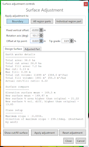‘Surface Adjustment’ allows you to make additional changes to the designs that were made in the layer creation.
- ‘Vertical offset’ which can be adjusted with up and down buttons at 0.01 increments or by typing in a set value to shift the design vertically up or down.
- ‘Rotation axis’ This can be adjusted by typing in a value, using the up and down buttons or by using the yellow dot that appears in the working area.
- ‘Offset at tip point’ works in conjunction with the ‘Rotation axis’ setting to make the changes along the set point.
- The bottom portion of the window displays information about the whole design surface and the adjusted part, including a comparison to the original elevation surface.
As you make changes, the cut/fill map will automatically adjust accordingly. Once you are done changing it, you need to accept or reject it by pressing either the ‘Apply adjustment’ or the ‘Reset adjustment’ button at the bottom.
# Structured Surface Warping
‘Structured Surface Warping™’ allows controlled manipulation of the field. This tool can be used to create non-standard designs.
- The warping area is designated by the blue square and can be manipulated by using the yellow anchor points.
- The blue numbers under each point in the pop-up window are the distance of each anchor from the central point.
- ‘Rotation (A->B)’ Displays the current heading of the line between the A point and the B point. The rotation can also be manually set in this option.
- The values corresponding to each anchor point will adjust the vertical shift of the surface around the area of said point.
# Combine Surfaces
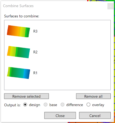Combine surfaces allows you to combine multiple elevation and design surfaces into a single layer. This tool can be used to:
- Combine multiple surveyed fields into a singular layer for a full farm view
- Combine separate region’s designs into a full design
- Combine a (possibly filtered) difference or cut/fill layer with an elevation surface.
Drag the layers you wish to combine into the pop-up window. Select what type you want the output layer to be before closing the tool.
NOTE: If there are any overlapping areas in the selected layers, it will pick the topmost in the list for the result.
# Expand/contract surface
The ‘Expand/contract surface’ tool allows you to make a surface larger or smaller.
To expand the surface:
Enter a positive value into the “Expand or contract” field. When making a surface larger, it takes the available information and makes an estimate to try to create the area outside the existing elevations. You can choose between these expansion methods:
- Flat: Simply uses the closest elevation point and extends based on that data
- Trend 1: Each new pixel is calculated from just the original elevation surface pixels. Pixels close to the edge use near elevations. Pixels further from the edge use existing elevations in a wider range.
- 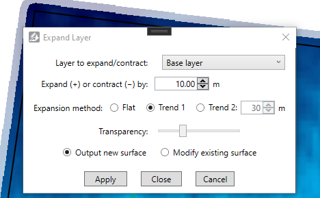Trend 2: Expands the field iteratively, in pixel layers out from the existing edge. An additional parameter is available for this method. It allows you to modify how far the pixel by pixel expansion of Trend 2 will look for elevations. A larger number will lead to a smoother expanded surface.
NOTE: Expanding a surface is by nature an estimate or guess. It will not be accurate.
To shrink the surface, enter a negative value into the “Expand or contract” field. When shrinking, elevation points will be deleted.
The option is also available to either create a new surface or to modify the existing surface. Select the appropriate button for this.
To calculate and apply the expanded or contracted surface, click the Apply button. Once it has been calculated, you may modify its transparency with the slider. To keep your new/changed surface, click the Close button.
# Shift Surface
The function of this tool is to horizontally offset whole surfaces. This can be done in whole pixel increments only. It is, however, advisable to avoid the need for this tool by chasing up the correct projection when importing, or to use markers to properly zero and determine your location accurately in the field.
# Change pixel size for all surfaces
The function of this tool is to change the size of the pixels across all surfaces. The pixel sizes are read in meters, for example if the pixel size is set to 2 then each square dot on the screen is equal to 2 square meters in the real world. The sizes available in T3RRA Design Plus go from 0.5 meters all the way up to 1024 meters.
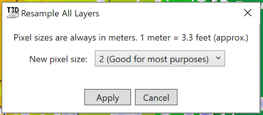The smaller the pixel size the more detail there will be on the surface in the working area and vice versa, however the smaller the pixel size the more strain T3RRA Design Plus will put on your computer, so use at your own discretion.
# Smooth Region Boundary
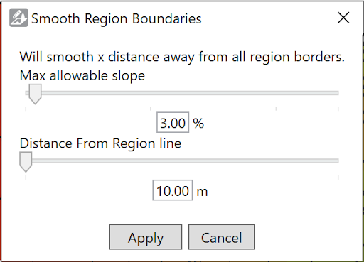‘Smooth Region Boundaries’ is used to smooth the transition between different regions in a design.
- The top slider is the ‘Max Allowable slope’. It sets the steepest allowable slope in the transition around the region lines.
- The bottom slider is ‘Distance From Region line’. This sets how far away from the region line blending can occur.
- Both values can be set manually by typing a value into the spaces available underneath the sliders.
# Create a cut/fill overlay
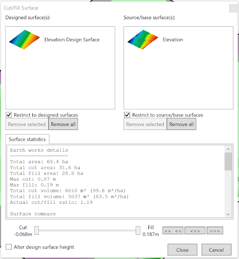‘Create a cut/fill surface’ creates a surface layer that shows how much soil must be moved to and from areas to reach the design surface.
- To create a cut/fill map start by selecting a design surface and dragging it into the left side box, and drag an original elevation surface into the right box.
- ‘Surface statistics’ displays the earth moving details between the 2 layers.
- The slider allows you to adjust the point of the largest fill and deepest cut and set whether the Cut/Fill surface should display heights equal to and within this range, equal to the slider points and outside the range or just everything equal to the range found.
# Show design surface balance figures
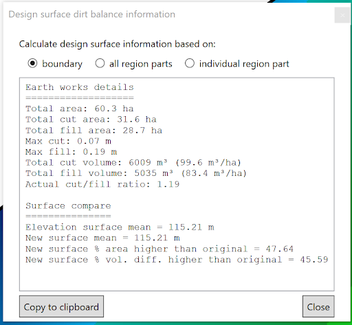This tool provides a separate output of the information that is available in other tools, this tool is limited to only design surfaces. This information displayed can be limited to the boundary, a single region or a group of regions.
# Layer Menu
- 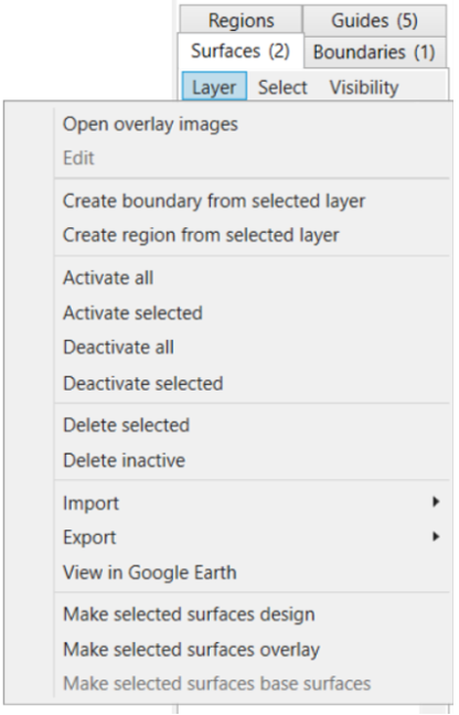Open overlay images - this allows layers (such as yields, or imagery etc) to be draped over the elevation layers. These layers are not used in any elevation related calculations and are denoted by the letter ‘O’ (overlay)
- Edit
- Create boundary from selected layer - this will draw a boundary around the most outer points of the selected surface and will populate a new boundary in the Boundary tab
- Create region from selected layer - this will draw a region around the most outer points of the selected surface and will populate a new region in the Region tab
- Activate all - this will activate the surface so it is now visible on the Working Area. This is shown by the checkbox being selected.
- Activate selected - this will activate the surface which you selected (shown by the tile having a blue highlight around it) so it is now visible on the Working Area. This is shown by the checkbox being selected.
- Deactivate all - this will deactivate all surfaces
- Deactivate selected - this will deactivate the surface which you currently have selected (shown by the tile having a blue highlight around it)
- Delete selected - deletes the surface you have currently have selected (shown by the tile having a blue highlight around it)
- Delete inactive - deletes all inactive surfaces (i.e. those without a tick in the checkbox)
- Import >
- T3RRA Cutta elevations (\*.tci) - see Importing elevations from T3RRA Cutta (.tci) in section: Importing and Exporting in T3RRA Design Plus
- From existing elevation surface - see Importing a Surface from an Existing Elevation Surface in section: Importing and Exporting in T3RRA Design Plus
- From raw data points (Deere RCD, CSV, etc) - see Importing a Surface from Raw Data Points in section: Importing and Exporting in T3RRA Design Plus
- View in Google Earth - this will open the selected surface in Google Earth
NOTE: You must have Google Earth Pro installed on your PC for this to work.
- Make selected surfaces design - this will change either a ‘base’ or ‘overlay’ surface/s to a ‘design’ surface and will be denoted by the letter ‘D’ on the surface/s tile
- Make selected surfaces overlay - this will change either a ‘base’ or ‘design’ surface/s to a ‘overlay’ surface and will be denoted by the letter ‘O’ on the surface/s tile
- Make selected surfaces base surfaces - this will change either a ‘design’ or ‘overlay’ surface/s to a ‘base’ surface