Full Field Design tools
- Design Functions
- AB Profile Tool
- Best-fit Design
- Multi-fit Design
- Smooth Design
- Regular Smoothing
- Directional Smoothing
- Region Blending
- Offset Design
Design Functions

Best-fit
'Best-fit' creates a plane of best fit for the field or region. The best-fit calculation produces the slope and direction required to achieve a single plane, while minimizing the amount of dirt moved.

Multi-fit
'Multi-fit' builds multiple smaller planes that follow the contours of the ground to drain water in a single direction, usually in the direction of irrigation and/or wheel tracks. The minimum and maximum slopes influence the individual plane design which will improve the drainage on a field while moving as little soil as possible by staying truer to the existing elevation gradients.

Smooth
'Smooth' is used to smooth out gradients on a surface. The strength of smoothing is adjustable to influence the smoothing effect. The option of region blending allows you to set a slope between regions on your field to allow for smooth transition between regions.

Offset
This tool alters a surface’s elevation by adjusting it up or down. This relates to the importing and exporting of dirt volumes. A use case might be the importing of an inch of topsoil which you want to spread evenly over an entire region or field.
AB Profile Tool

AB Profile Tool - In the Design step of T3RRA Cutta Desktop, the AB Profile Tool allows the user to draw an AB line anywhere on the surface and view the side profile of the elevation between the two nodes. Access the tool using the icon above in the bottom left corner of the map. The square node is the "anchor" and point "A" and will represent the left hand side of the graph, and the round node can be moved to extend the line and set the "B" point representing the far right of the graph. Use this tool to get a better visual representation of the slope anywhere on the surface.


Here is a video on the AB Profile Tool.
Best-fit Design
'Best-fit' creates a plane of best fit for the field or region. The best-fit calculation produces the slope and direction required to achieve a single plane, while minimizing the amount of dirt moved.
A Best-fit design provides a single plane that most accurately fits the existing topography. Using a Best-fit plane ensures that you move the least amount of dirt possible to create a single plane for a field. Note that this can still result in large amounts of dirt being moved.
Tip: Dividing the field into regions, then fitting single planes to each region can help to decrease dirt volumes.
Enter design details to create a plane, or instruct the T3RRA software to auto-calculate your design details.

Setting slope parameters
The software will try to find the most appropriate line of best fit, however the primary and secondary slopes can also be manually set.
(It is recommended that only users with a good understanding of Laser Plane systems use manual settings)
To manually set the primary slope direction check the box labeled 'Manually set primary slope direction'.
When in doubt, consult an irrigation engineer.
Cut/fill ratio, Max cut depth, & Import can be set in 2 locations. The defaults that will be applied to new projects can be set in the Project tab of settings (see section B) or in the lower left corner of the Best-Fit (and Multi-Fit) page.

The 'Cut/fill ratio' is determined by the type of material being moved and how much of it will “settle” or “shrink” once compacted. This value depends on soil characteristics.
Enter a 'Max cut' for the maximum allowed cut depth. The following warning will appear to notify you if any points on the map exceed the max cut depth. adjustments may be required.

The 'Import' section is used when you need to bring in dirt from a stockpile or export dirt from the field to another area. Change the amount to a negative value for exporting.
Multi-fit Design
Select the 'Multi-fit' button to create an optimized non-linear surface with slopes between the entered minimum and maximum. Multi-fit balances the dirt down the field in the direction you specify. The balancing occurs within strips, and is great for working within rows and moving minimal dirt.
• A Multi-Fit design allows the slopes to vary within set tolerances and can greatly reduce the amount of dirt moved.
• Dividing the field into regions can further decrease the dirt movement required. Enter details in the below panel and into all fields to generate a Multi-fit plane.
NOTE: If ‘min%’ or ‘max%’ are left blank the design results will not be desirable.

'Set slope range'
You can use the iGrade™ Plane Calculator to find out the average slope percentage. Alternatively you can find this in T3RRA Cutta by doing a plane of best fit in a direction and then looking at the primary and cross slopes in the plane statistics window. If in doubt, consult an irrigation engineer.
'Perform cross-strip optimization'
This will attempt to tilt the strip sections to match the actual side slope present. Use in fields that have high side slopes (>2% slope). It is unlikely to provide any benefit in relatively flat fields. (this is enabled by default)
'Perform preliminary side slope adjustment'
This will cause an initial side slope adjustment to occur. It will attempt to ensure that the side slope is no greater than the minimum row slope (use if water might have a tendency to run across rows rather than down the rows).
Cut/fill ratio, Max cut depth, & Import can be set in 2 locations. The defaults that will be applied to new projects can be set in the Project tab of settings (see section B) or in the lower left corner of the Multi-Fit (and Best-Fit) page.

The 'Cut/fill ratio' is determined by the type of material being moved and what percentage of it will “settle” or “shrink” once compacted.
Enter a 'Max cut depth' for the maximum allowed cut depth. The following warning will appear to notify you if any points on the map exceed the max cut depth. adjustments may be required.
The 'Import' section is used when you need to bring in dirt from a stockpile or export dirt from the field to another area. Change the amount to a negative value for exporting.
Smooth Design

Select the 'Smooth' button to create a more regular surface with fewer and more gradual ridges and dips. The smoothing strength can be adjusted to produce a stronger or lesser effect as needed.
Before

After

Regular Smoothing
Regular smoothing applies an averaging filter to the surface of the field to remove bumps and dips. 
The ‘Smoothing strength’ slide bar controls how smooth it is by increasing the radius that is used in calculations. The smaller the slider value, the less of an effect the smoothing will have.
Smoothing can be applied to the whole field, or to individual regions. It can be applied to the original surface, or to an existing design.
Directional Smoothing
'Directional smooth' is a check box just below regular smoothing.
Directional smoothing causes the smoothing effect to be stronger in a particular direction and weaker in the perpendicular direction.
Enter the primary smoothing direction in the provided text box.
'Smoothing strength in the primary direction' allows you to set the influence radius in that direction.
'Smoothing strength in the secondary direction' controls the influence radius at a 90 degree angle to the primary direction.

Region Blending
Region blending allows you to “feather” the edges of regions to allow for smooth transitions between regions.
'Max Allowable slope' lets you set the maximum steepness that can be used to achieve a region blend.
'Distance from Region line' limits how far into each region the blend can go, in order to help make sure that other design elements are not affected.
NOTE: changes made with region blending may not be obvious in 2D view but can be much more prominent in 3D view, or in the cut/fill map.
Press 'Apply' after parameters are entered in order to see effects.
Before

After

Offset Design
Select the 'Offset' button to raise or lower the surface height of a field or region.

This can help with:
-
Importing and exporting dirt
-
Addition or removal of topsoil
-
Raising pads


You can either:
-
manually enter the desired offset amount (this can also be adjusted in set increments using the up and down arrows)
-
use the calculator to help set the offset amount. The calculator is useful if you want to offset the surface by a certain volume of imported or exported dirt.
-
Formular
Left over volume = (Cut/Fill ratio * Volumn of cut) + Volume of fill.
Result = (Import + Left over volume) / Selected area
-
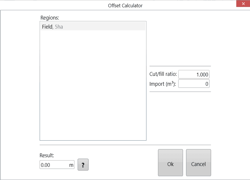
Negative import values are considered exports.
Press 'Apply' (shown as the offset design icon) after parameters are entered.
Once you are happy with the design follow the steps in the 'completing your design' section.