Appendix A | COMMAND Settings Reference
Introduction
The COMMAND Settings pages provide access to the configuration and diagnostic functions of the COMMAND Electronic Control Unit (ECU).
During a new installation, these pages are used to commission the machine as described in Chapter 3 | Dealer Commissioning. Once commissioning has been completed, they primarily serve as a reference for viewing configuration, performing maintenance and assisting with diagnostics.
Unless instructed otherwise, operators should not need to modify these settings during normal operation.
A.1 | COMMAND Settings Overview
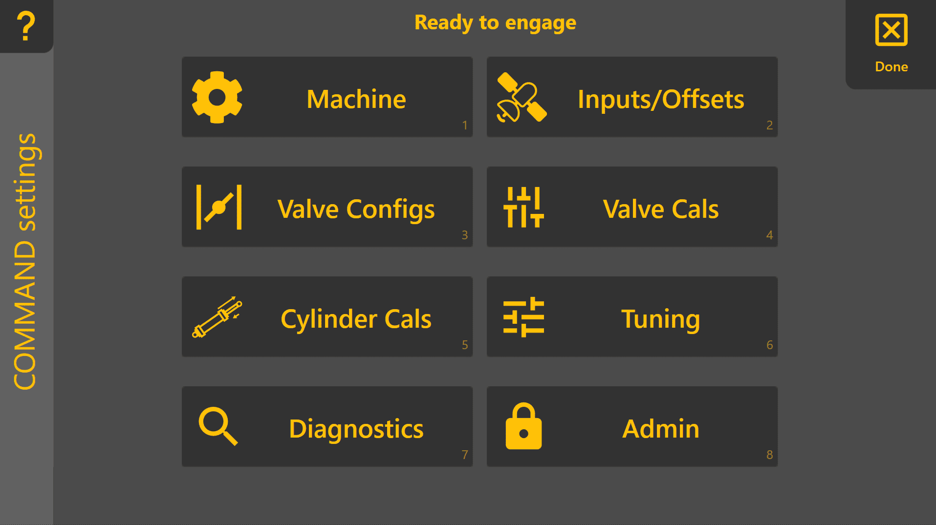
The COMMAND Settings home page groups the ECU configuration into a number of logical sections.
During commissioning, these pages are generally completed from top to bottom. If a configuration issue is detected, an indicator may be shown beside the relevant page to assist with troubleshooting.
A.2 | Machine
The Machine page defines the overall machine configuration used by the COMMAND ECU.
Typical functions include:
- Selecting the machine profile
- Viewing ECU connection status
- Confirming the active machine configuration
This page is generally configured once during installation and rarely requires further adjustment.
See Section 3.2 for commissioning instructions.
A.3 | Inputs & Offsets
The Inputs & Offsets page configures the positioning sensors connected to the system.
Typical settings include:
- GNSS receiver selection
- Receiver offsets
- Implement geometry
- IMU configuration
- Position source assignment
These settings determine how the system calculates the position of the implement relative to the design surface.
Changes should only be made if hardware has been replaced, repositioned or recalibrated.
See Section 3.4 for commissioning procedures.
A.4 | Valve Configurations
The Valve Configs page defines how the COMMAND ECU interfaces with the machine's hydraulic system.
Depending on the installation, this may include:
- Hydraulic output type
- Valve interface selection
- Joystick inputs
- Automatic control enablement
- Output direction assignment
This page should only require changes when installing on a different hydraulic system or replacing major components.
See Section 3.5 for configuration instructions.
A.5 | Valve Calibration
The Valve Calibration page adjusts the hydraulic output range used during automatic control.
Calibration determines:
- The minimum output required to begin implement movement.
- The maximum output that provides full operating speed without excessive hydraulic or mechanical stress.
Correct calibration allows automatic control to operate smoothly across the full available hydraulic range.
See Section 3.6 for calibration procedures.
A.6 | Cylinder Calibration
Cylinder calibration compensates for differences in hydraulic cylinder geometry and operating speed.
The calculated cylinder ratio improves tracking performance by ensuring extension and retraction movements remain balanced.
Cylinder calibration should normally only be repeated after hydraulic repairs or changes to the implement.
See Section 3.7 for calibration procedures.
A.7 | Automatic Control
The Automatic Control page contains tuning parameters used to optimise grading performance.
Examples include:
- Acquire Sensitivity
- Tracking Sensitivity
- Look Ahead
- Additional control parameters
Most machines will perform correctly using the default values established during commissioning.
These settings should only be adjusted when fine-tuning machine performance or when requested by T3RRA Support.
See Section 3.9 for recommended tuning procedures.
A.8 | Diagnostics
The Diagnostics page provides live information from the COMMAND ECU.
Typical information includes:
- Sensor status
- GNSS information
- IMU data
- Hydraulic outputs
- ECU status
- Diagnostic messages
This page is intended primarily for fault finding and support.
T3RRA Support may request information from this page when investigating a problem.
A.9 | Tech Mode
Tech Mode exposes additional engineering and diagnostic settings intended for advanced commissioning, development and technical support.
These parameters are not required for normal machine operation and may affect system performance if modified incorrectly.
Only change Tech Mode settings when instructed by T3RRA Support.
A.10 | Administrative Functions
The Admin page contains maintenance and service functions for the COMMAND ECU.
Depending on software version, these may include:
- Software updates
- Reset or maintenance functions
- Configuration management
- Service information
Administrative functions should generally only be used during commissioning, servicing or under the guidance of T3RRA Support.