**Blade Shift changes the current Target—not the Design.** Remove the applied shift at any time to return Automatic Control to the original design surface. If large Blade Shift values become necessary, verify the project alignment and consider performing **Zero** instead.
To access the Blade Shift controls from the Apply View: [](https://docs.t3rra.com/uploads/images/gallery/2026-06/jdJ7aPFb0dL7kNGT-image.png) **Press Blade Shift.** [](https://docs.t3rra.com/uploads/images/gallery/2026-06/74TgIUkRyCaW1uXd-image.png) #### [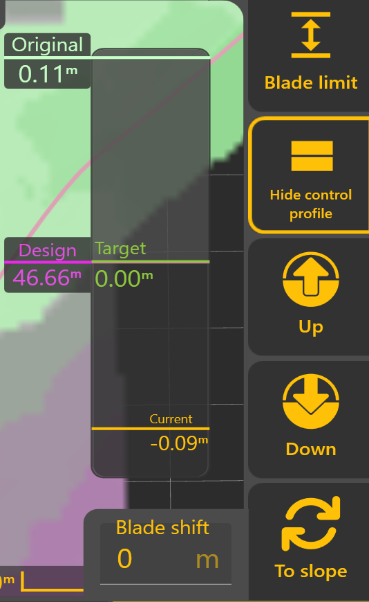](https://docs.t3rra.com/uploads/images/gallery/2025-10/jWRnJkGMLwE6RLwJ-image.png) ### Understanding the Control Profile The **Control Profile** provides a live cross-sectional view of the current grading state. It allows the operator to see how the original ground, Design, Target Position and current implement position relate to one another during **Automatic Control**. The Control Profile displays four key references: #### Original The original surveyed ground surface before grading began, shown relative to the Design. #### Design The intended finished surface. This remains fixed throughout the project and represents the final grading objective. #### Target The position currently being tracked by **Automatic Control**. Normally, the Target matches the Design. However, **Blade Shift** or **Dynamic Cut & Fill Limiting** may temporarily adjust the Target during grading. #### Current The current implement position relative to the Design. As **Automatic Control** operates, the Current position should progressively move towards the Target. ### [](https://docs.t3rra.com/uploads/images/gallery/2026-06/MG8RP10Mpsf8H8OH-image.png)Blade Shift The **Up** and **Down** buttons temporarily raise or lower the Target by the configured **Blade Shift Increment**. Multiple adjustments can be applied as required, and the current Blade Shift value is displayed within the **Blade Shift** window. Selecting the displayed value allows a specific offset to be entered directly. ### Dynamic Cut & Fill Limiting [](https://docs.t3rra.com/uploads/images/gallery/2026-06/5QNIparU1eiZEGRE-image.png)**Dynamic Cut & Fill Limiting** temporarily restricts how much material **Automatic Control** attempts to remove or place during a single pass. Rather than immediately targeting the finished Design, **Level COMMAND** calculates a temporary Target Position that respects the configured Cut or Fill Limit. As grading progresses, the Target automatically moves towards the Design until the finished surface is achieved. [](https://docs.t3rra.com/uploads/images/gallery/2026-06/hMvtO5HvXsy72yOf-image.png)Dynamic Cut & Fill Limiting is useful for: - Removing material over multiple controlled passes. - Reducing machine load. - Preventing excessive cutting or filling in a single pass. - Improving control on difficult ground. ### [](https://docs.t3rra.com/uploads/images/gallery/2026-06/G8n3SH6xjqIo88hQ-image.png)Manual X-Slope Adjustment Machines equipped with **Height & X-Slope** control can temporarily adjust the target cross-slope. Select **To Slope** to switch from Blade Shift controls to X-Slope controls. ### [](https://docs.t3rra.com/uploads/images/gallery/2026-06/sAjhmI6RPZrrI4UG-image.png) When **X-Slope Auto** is enabled, **Level COMMAND** automatically follows the Design cross-slope. When **Auto** is disabled, the operator may manually adjust the target cross-slope using the **Left** and **Right** controls or enter a specific value directly. Select **To Shift** to return to the Blade Shift controls. ### Blade Shift Increment [](https://docs.t3rra.com/uploads/images/gallery/2026-06/VqQ89Qc0hnMKD0n4-image.png)The amount applied by each press of the **Up** or **Down** buttons is determined by the configured **Blade Shift Increment**. Likewise, manual X-Slope adjustments use the configured **X-Slope Shift Increment**. To change the Blade Shift Increment, from the Apply View press: **More → Blade Shift Settings** Smaller increments provide finer control, while larger increments allow quicker adjustments during grading. Typical **Blade Shift Increment** values are:| Units | Recommended Increment |
|---|---|
| Metres | 0.01–0.02 m |
| Inches | 0.4–0.8 in |
| Feet | 0.03–0.06 ft |
**Operator Tip:** Use **Blade Shift** to make temporary grading adjustments as conditions change throughout the day. If large Blade Shift values become necessary to maintain the desired grade, verify the project alignment and consider performing **Zero** again rather than continuing to increase the applied offset.
Continue to **6.5 | Position Quality & GNSS Validation** to understand how **Level COMMAND** validates positioning information before Automatic Control is allowed to operate.