6.1 | Understanding Surface Layers
Every grading operation performed by Level COMMAND is based on one or more surface layers. Although only a single machine is moving across the field, Level COMMAND continuously compares several different representations of the terrain to determine where the implement should be positioned.
Understanding how these surface layers relate to one another makes it much easier to understand Automatic Control, Blade Shift, Cut/Fill Limiting and the information displayed throughout the Apply View.
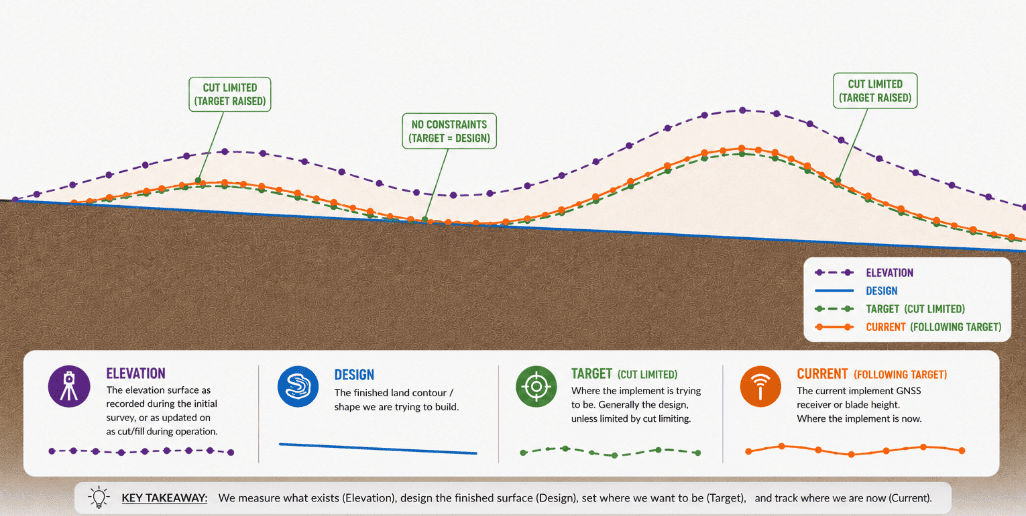
The diagram above illustrates the relationship between the four primary surface layers used during grading. Although each layer serves a different purpose, they work together to guide the implement towards the finished design.
Existing Ground (Elevation)
The Elevation surface represents the terrain as it currently exists.
This surface is typically created by surveying the work area before grading begins, although it may also be imported as part of a pre-designed project. The Elevation surface records the natural shape of the ground, including slopes, depressions and other terrain features.
As grading progresses, the original Elevation surface remains unchanged and continues to represent the ground before any earthmoving took place.
Design Surface
The Design surface represents the desired finished ground profile.
It may be:
- Created directly within Level COMMAND using a Plane Project.
- Imported from external design software as part of a pre-designed project.
Unlike the Elevation surface, the Design surface normally remains unchanged throughout the grading operation. It defines the final surface that the operator is working towards.
Target Position
The Target surface is the position that Level COMMAND is currently attempting to guide the implement towards.
Under normal operation, the Target surface is derived from the Design surface. Depending on the selected control mode and operator settings, the Target may temporarily differ from the Design while still guiding the implement toward the same finished result.
Examples include:
- Blade Shift
- Dynamic Cut Limiting
- Dynamic Fill Limiting
- Blade Control Modes
This distinction is important. Level COMMAND maintains the relationship between the implement and the current Target surface, while the Design surface remains the long-term grading objective.
Current Position
The Current position represents the measured location of the implement relative to the Target surface.
As the machine moves, Level COMMAND continually compares the Current position with the Target surface to determine whether the implement needs to raise, lower or maintain its present position.
The difference between the Current position and the Target surface is referred to as the Current Error, which is displayed throughout the Apply View and used by Automatic Control.
Surface Interpolation
Survey data consists of individual measured points rather than a continuous surface.
To create a usable grading model, Level COMMAND interpolates between the recorded survey points to form a continuous terrain surface. This allows the system to determine elevations at locations between individual survey measurements.
The quality of this surface depends on the quality of the original survey.
Generally:
- Higher survey density produces a more accurate representation of the terrain.
- Sparse survey data may smooth or omit smaller terrain features.
- Poor-quality survey data cannot be fully corrected by Automatic Control during grading.
For this reason, accurate surveying is an important foundation for achieving accurate grading results.
Surface Updates During Grading
Not every surface changes during operation.
| Surface | Updated During Grading |
|---|---|
| Elevation | No (represents the original surveyed ground) |
| Design | No (represents the desired finished surface) |
| Target | Yes (may change due to Blade Shift, Cut/Fill Limiting or other operating modes) |
| Current | Continuously (tracks the live implement position) |
| As Applied Elevation | Yes (records the surface produced during grading) |
| As Applied Cut/Fill | Yes (records remaining cut and fill after grading progress) |
The As Applied surfaces provide a continuously updated representation of the work being performed. These are the surfaces displayed when viewing the As Elevation or As Cut/Fill map layers in the Apply View, allowing operators to monitor grading progress as work is completed.
Operator Tip: Think of the surface layers as answering five different questions: Elevation — What does the ground look like today?
Design — What do I want it to look like when I'm finished?
Target — Where should the implement be right now?
Current — Where is the implement right now?
As Applied — What have I actually built so far?
Once you understand how these surface layers interact, the operation of Automatic Control, Blade Control Modes, Blade Shift and the other features described throughout this chapter becomes much easier to understand.