5.4 | Plane Projects & Surface Creation
Plane Projects allow simple design surfaces to be created without first surveying the entire work area. They are commonly used for creating flat pads, graded surfaces, drain batters and other simple earthworks. Each Plane Project can contain up to four individual Plane surfaces, making it easy to switch between different work areas or design surfaces without creating additional projects.
Creating a Plane Project
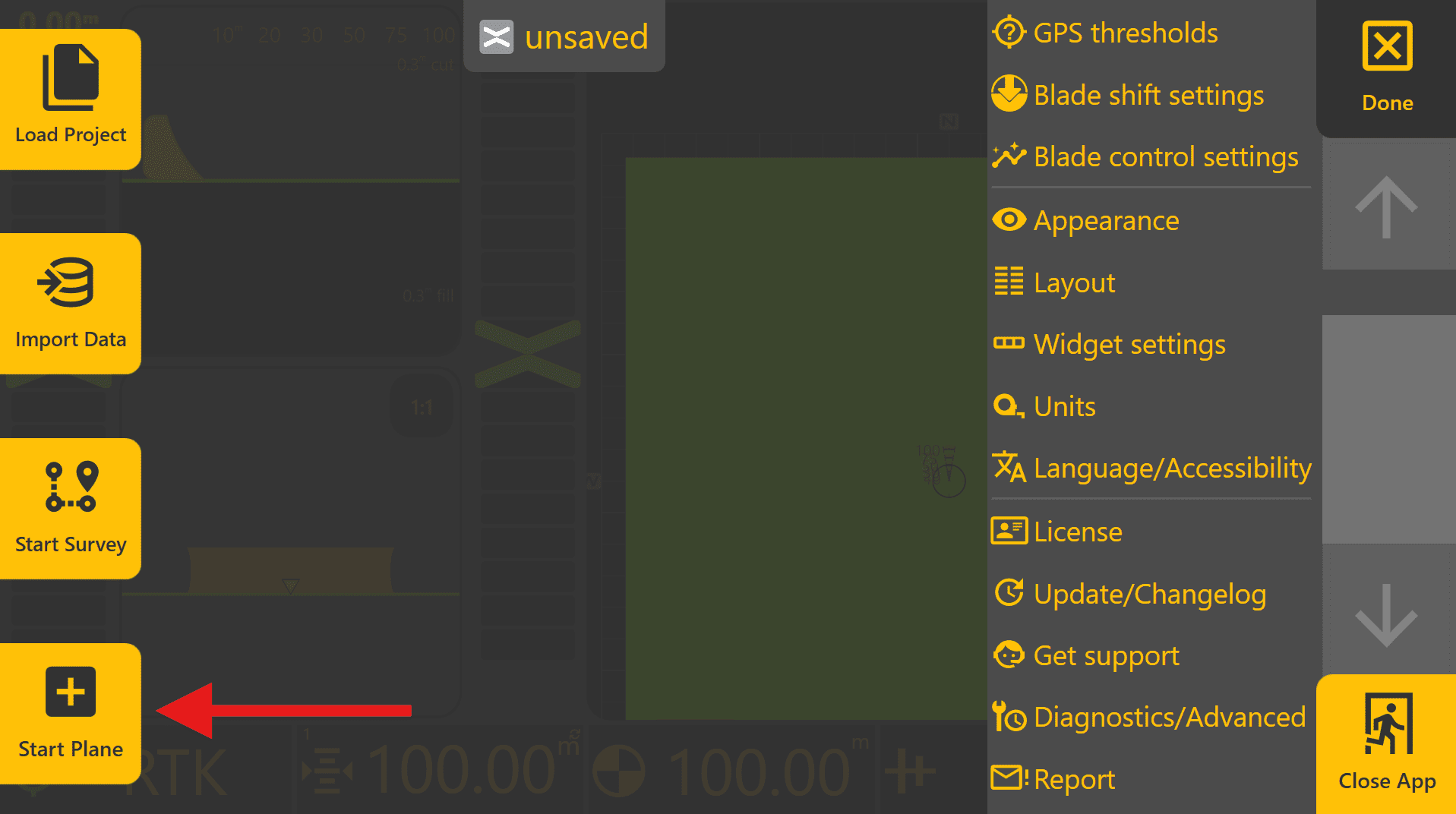
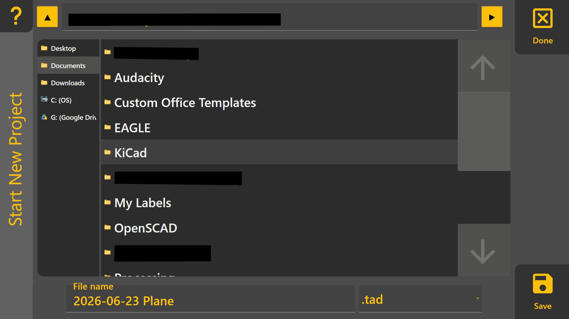
Selecting and Managing Plane Surfaces

Press Planes on the right side of the Apply View to display the available Plane slots.
Up to four Plane surfaces can be stored within a single Plane Project. Each Plane can have its own:
- Name
- Size
- Origin Point
- Primary Slope
- Secondary Slope
- Elevation Offset
To create a new Plane, select any unused slot labelled Create and the Plane Editor will open on the right side of the screen.
To switch between existing Planes, select the desired Plane from the list. The active Plane is indicated by a yellow outline.
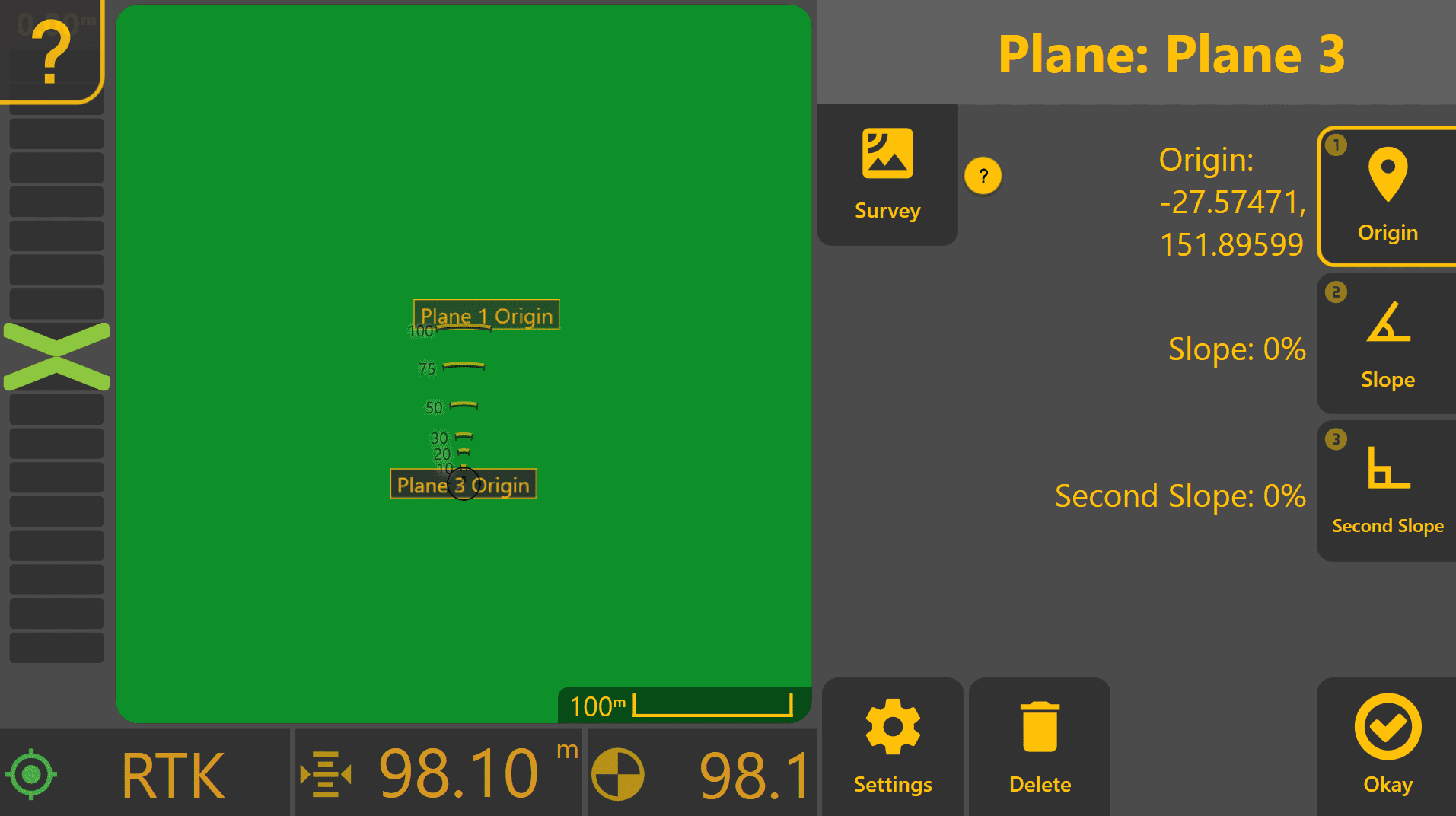
To edit an existing Plane, select it and then select it again to open the Plane Editor. The Plane Editor is used to define and modify all Plane properties, including origin, slopes and survey-based Plane generation.
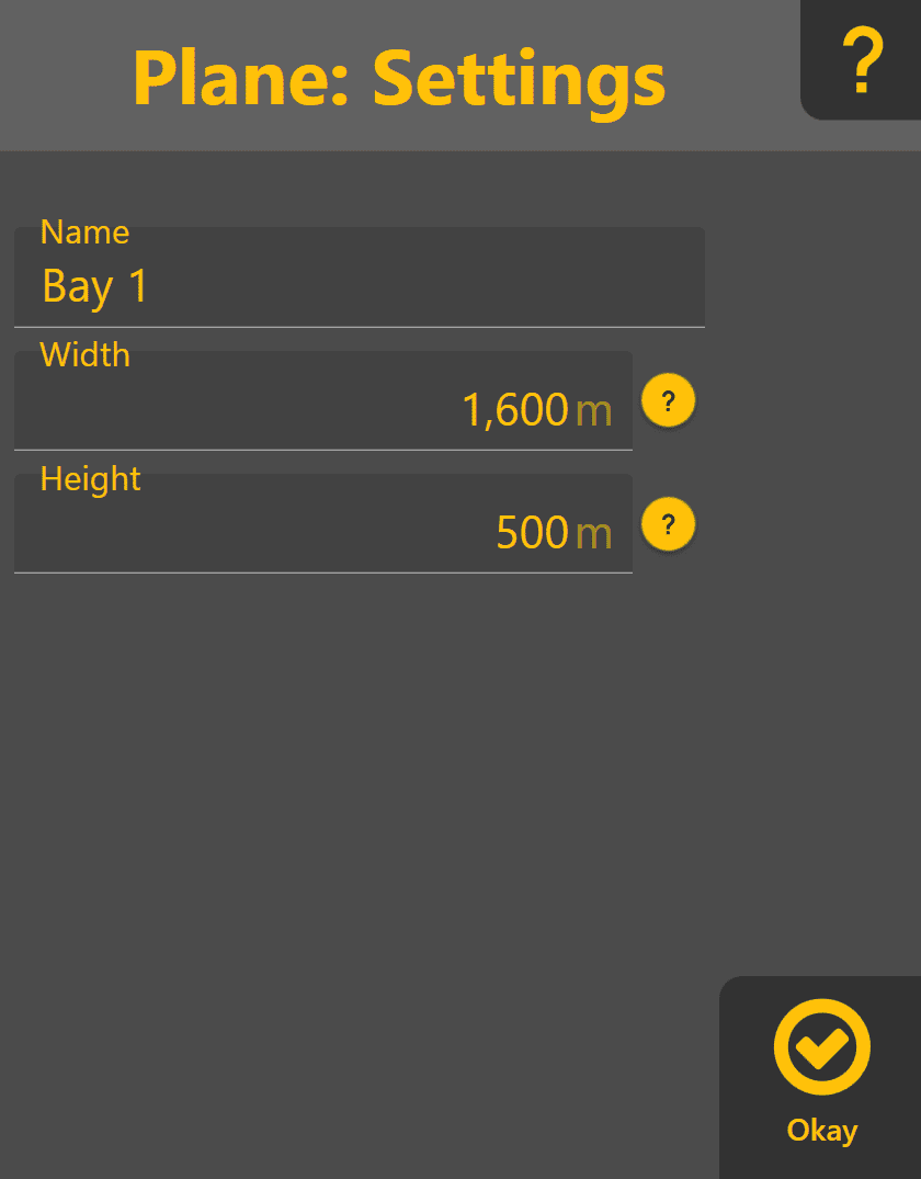
Plane Settings
Press Settings within the Plane Editor to configure the Plane name and dimensions. Assigning a meaningful Name makes it easier to identify different work areas within a project.
Plane Width and Height determine the visible extent of the generated Plane surface. These values may be adjusted at any time without affecting the calculated grade of the Plane.
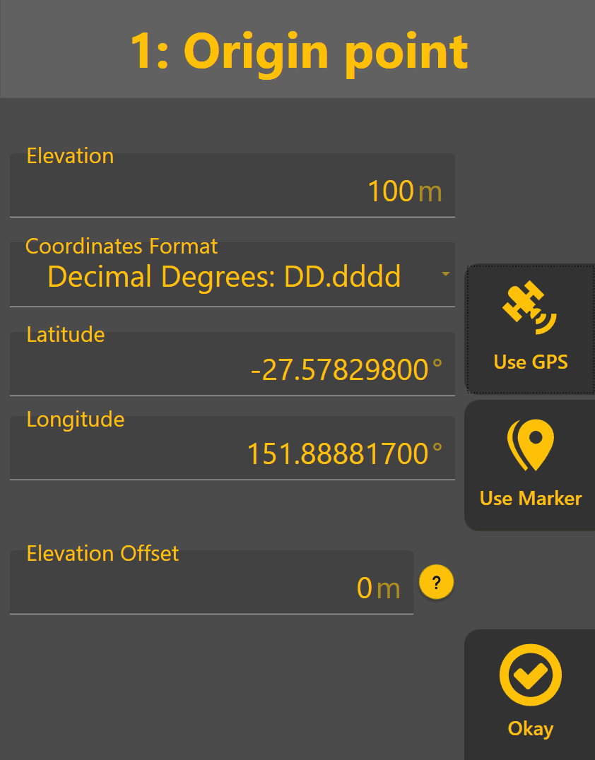
Defining the Origin Point
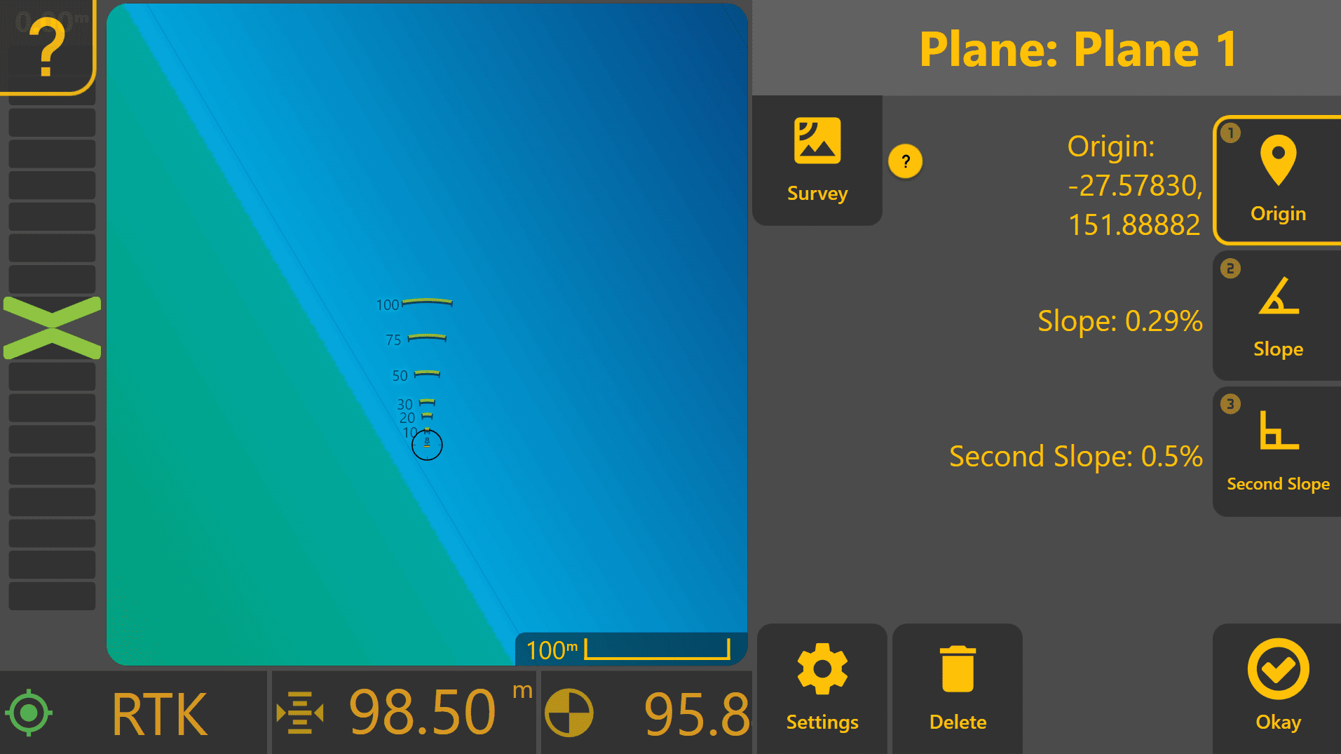
The Origin Point is the reference position used to define the Plane elevation and calculate all Plane slopes. It can be thought of as the anchor point of the Plane.
Press Origin within the Plane Editor to define or modify the Origin Point.
The Origin may be defined using:
- Use GPS – Sets the Origin to the current implement position and elevation.
- Use Marker – Uses an existing marker as the Origin Point.
- Manual Coordinates – Allows Latitude, Longitude and Elevation values to be entered directly.
Manual coordinate entry is commonly used when creating a Plane from a surveyed benchmark or known control point.
Once the Origin has been defined, press Okay to return to the Plane Editor. A newly created Plane will initially be flat, with the Origin positioned at the centre of the surface.
Elevation Offset
Elevation Offset allows the entire Plane to be shifted vertically without changing the underlying Plane definition. This is commonly used to quickly raise or lower a design surface when filling, trimming or removing surface irregularities while preserving the existing Plane slopes.
Positive values raise the Plane. Negative values lower the Plane.
Coordinate Formats
The Coordinate Format setting changes how Latitude and Longitude values are displayed. This is a display preference only and does not affect the actual position of the Plane.
Defining the Primary Slope
The Primary Slope defines the main grade direction of the Plane and determines how the surface rises or falls across the work area. Press Slope within the Plane Editor to define the Primary Slope.
The Primary Slope may be created automatically by using a second point on the desired grade surface:
-
Position the machine at the desired second point on the Plane.
-
Place the blade on the ground or at the desired design elevation.
-
Press Use GPS.
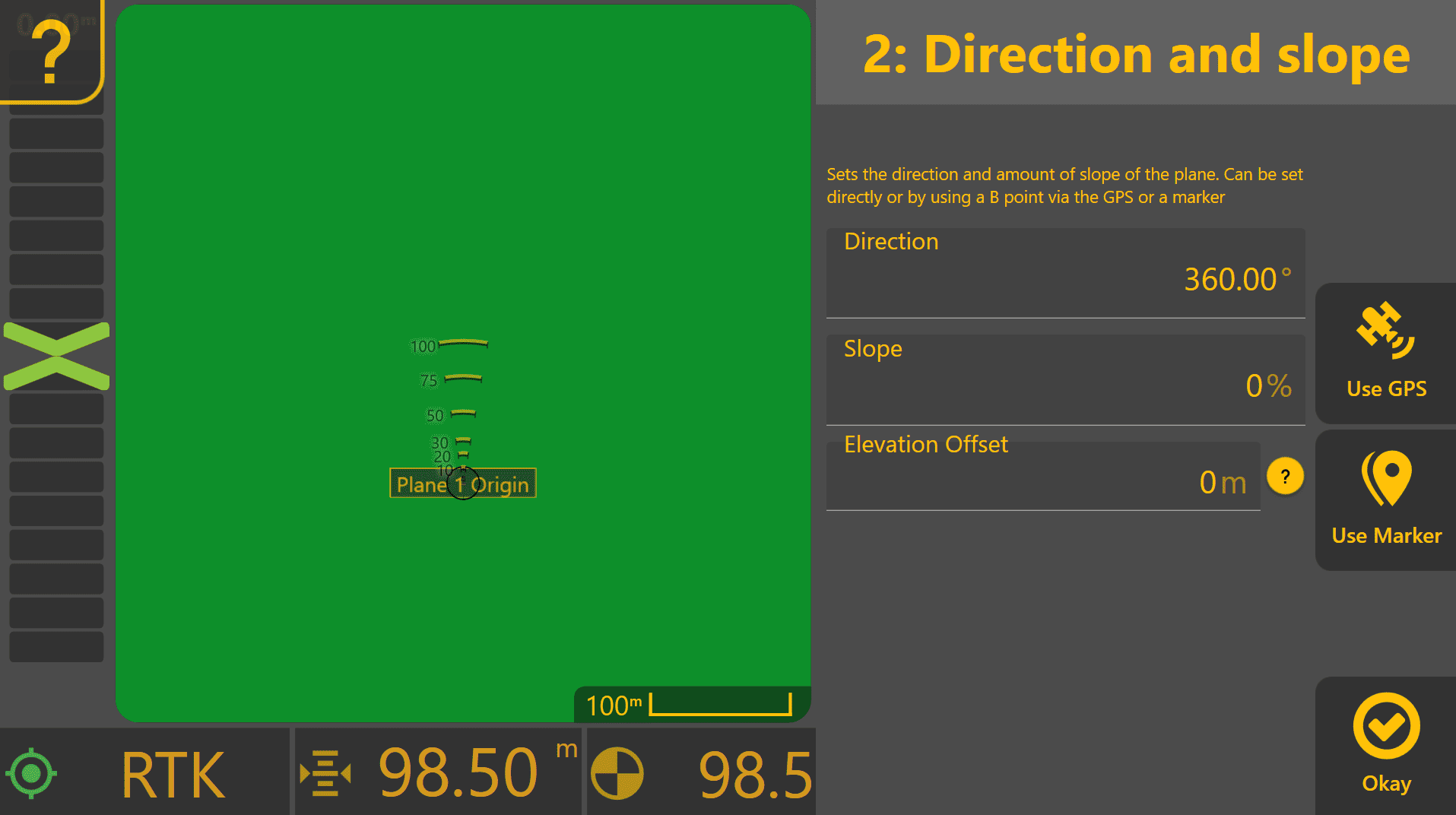
Level COMMAND will calculate the slope and direction between the Origin Point and the selected location, then update the Plane surface automatically. Alternatively, the slope percentage and direction may be entered manually if the desired grade is already known.
Once the desired slope has been defined, press Okay to return to the Plane Editor.
Direction
Direction determines the heading along which the Primary Slope is applied.
Slope
Slope determines how steeply the Plane rises or falls along the selected direction. Slope values are expressed as a percentage:
Slope (%) = 100 × Rise ÷ Run
Use GPS
Calculates the slope and direction automatically using the current implement position and the Origin Point. The calculated values may be edited afterwards if required.
Use Marker
Calculates the slope and direction using a previously created Marker and the Origin Point. The calculated values may be edited afterwards if required.
Defining the Secondary Slope
The Second Slope (X-Slope) defines the cross-fall of the Plane at right angles to the Primary Slope. This is commonly used when creating crowned surfaces, side-falls, drain batters or other surfaces requiring grade in two directions.
Press Second Slope within the Plane Editor to define the Secondary Slope. As with the Primary Slope, the Secondary Slope can be generated automatically using a second reference point:
-
Position the machine at a point representing the desired cross-fall of the Plane.
-
Place the blade on the ground or at the desired design elevation.
-
Press Use GPS.
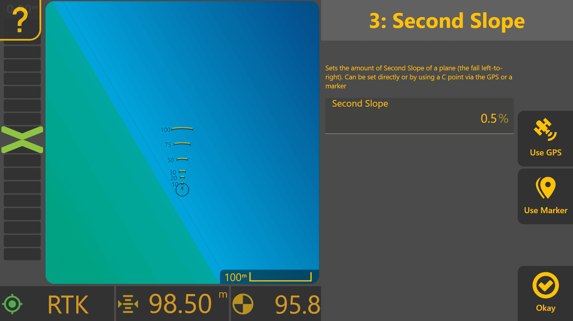
Level COMMAND will calculate the Secondary Slope relative to the Origin Point and update the Plane surface automatically. Alternatively, a known Secondary Slope percentage may be entered manually.
Unlike the Primary Slope, direction does not need to be specified because the Secondary Slope is always applied at 90 degrees to the Primary Slope.
Once the desired Secondary Slope has been defined, press Okay to return to the Plane Editor.
The final Plane surface is calculated using the Origin Point, Primary Slope and Secondary Slope together to define the overall grade of the design surface.
Surveying & Generating A Best Fit Plane
 When the desired Plane slope and direction are not known, Level COMMAND can survey an area and automatically generate a best-fit Plane surface.
A best-fit Plane represents the average grade of the surveyed area by calculating the most suitable Plane from the collected survey positions and elevations.
This workflow is commonly used when:
- Levelling an existing paddock while maintaining the current fall.
- Smoothing high and low spots without significantly changing overall drainage.
- Creating a Plane surface when the desired grade has not been surveyed or designed beforehand.
- Quickly generating a reference surface for testing and machine setup.
Creating a Best-Fit Plane
- Press Planes from the Apply View.
- Select an available Plane slot.
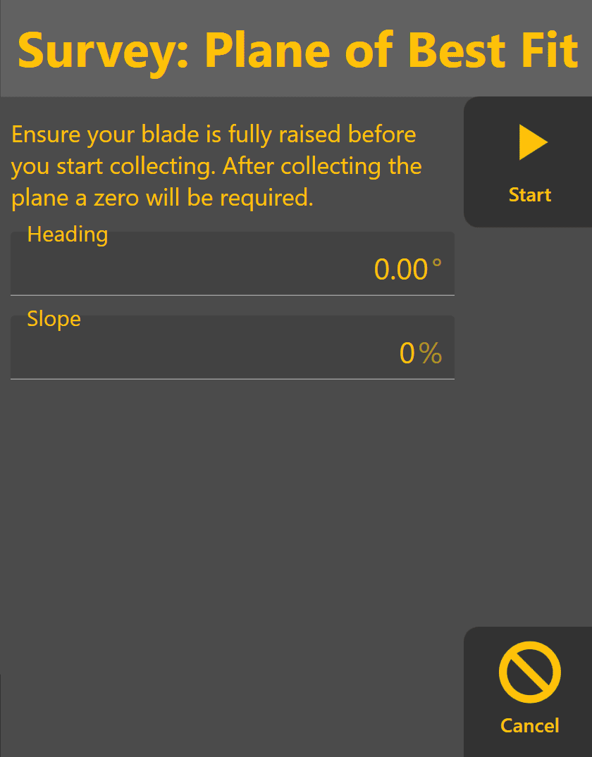
- Press Survey.
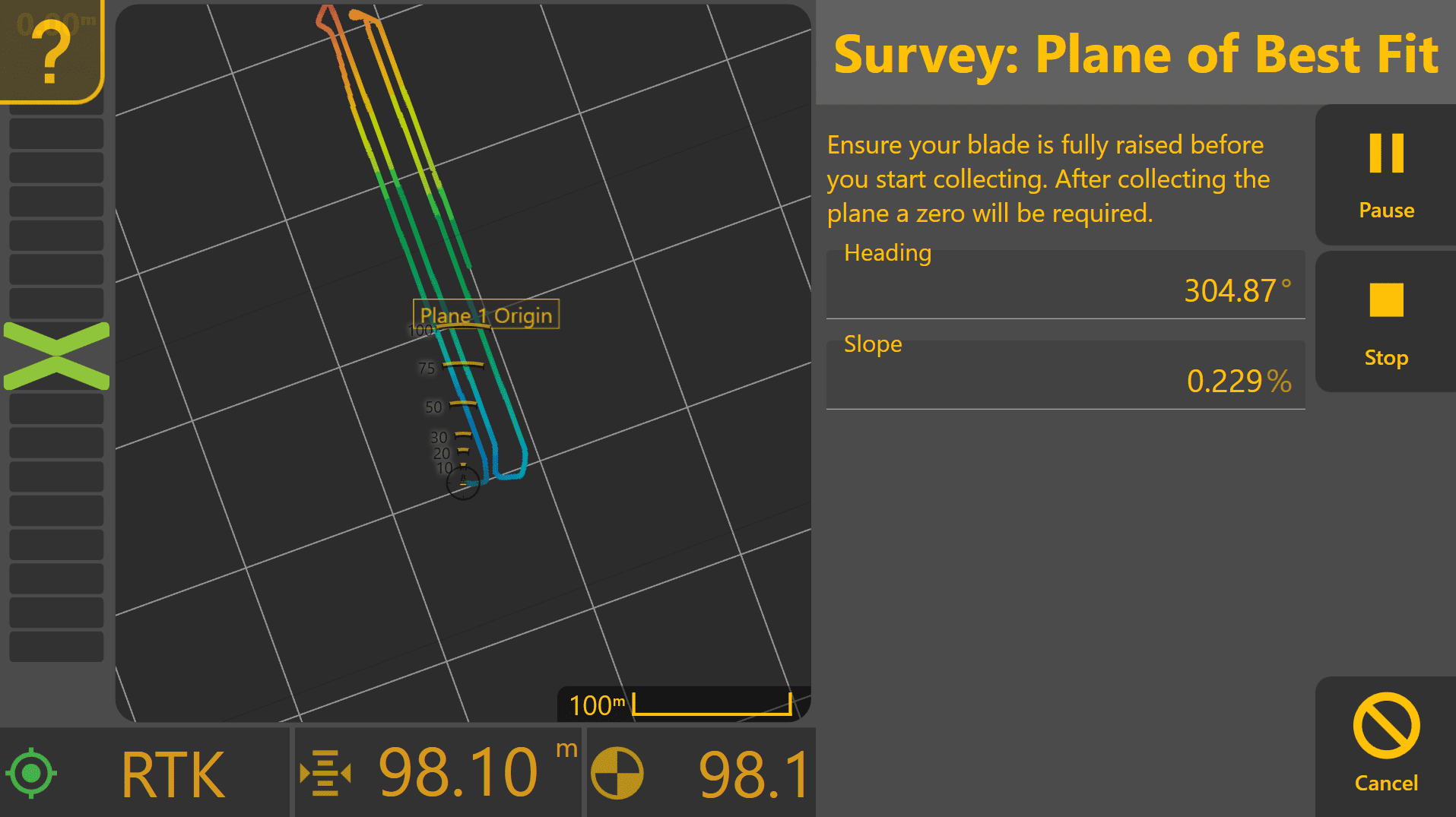
- Press Start to begin recording survey points.
- Drive throughout the area to be represented by the Plane surface.
- Press Stop once the survey is complete.
Level COMMAND will analyse the collected survey points and automatically calculate a best-fit Plane.
Once generated, the calculated Plane will be displayed and can immediately be used for Automatic Control.
Surveying Tips
For best results:
- Survey the entire area that will be worked.
- Collect points from both high and low areas.
- Avoid surveying only a small section of the work area.
- Raise the implement while surveying to avoid unintended grading. Once surveying has started, maintain a consistent implement height and avoid making manual height adjustments until the survey is complete.
As additional survey points are collected, the calculated Plane heading and slopes will generally become more stable and representative of the surveyed area.
Reviewing the Calculated Plane
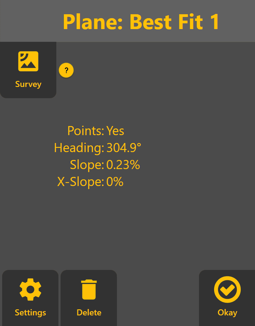 Once the Plane has been generated, selecting the Plane from the Planes menu will display the calculated:
- Heading
- Primary Slope
- Secondary Slope (X-Slope)
These values may be entered into a new plane if adjustment is required.
Additional Controls
The following controls remain available while working with a surveyed Plane:
- Settings – Modify the Plane name and dimensions.
- Delete – Remove the Plane and free the slot for reuse.
- Survey – Perform a new survey and recalculate the Plane.
- Okay – Save the Plane and return to the Apply View.