4.6 | Performing Your First Pass
Understanding the Operator's Role
Level COMMAND automatically controls the implement to follow the selected design surface, but it does not decide where material should be moved from or where it should be placed.
The operator remains responsible for planning the earthmoving operation, including:
-
Selecting suitable cut and fill areas.
-
Determining haul directions and travel paths.
-
Deciding where material should be sourced from.
-
Deciding where material should be placed.
Careful planning can significantly improve productivity by reducing unnecessary material movement and minimising rework. Material that is moved multiple times before reaching its final location increases both operating time and fuel consumption.
Monitoring Automatic Control
Once Automatic Control is engaged, monitor the Apply View to verify that COMMAND is operating as expected.
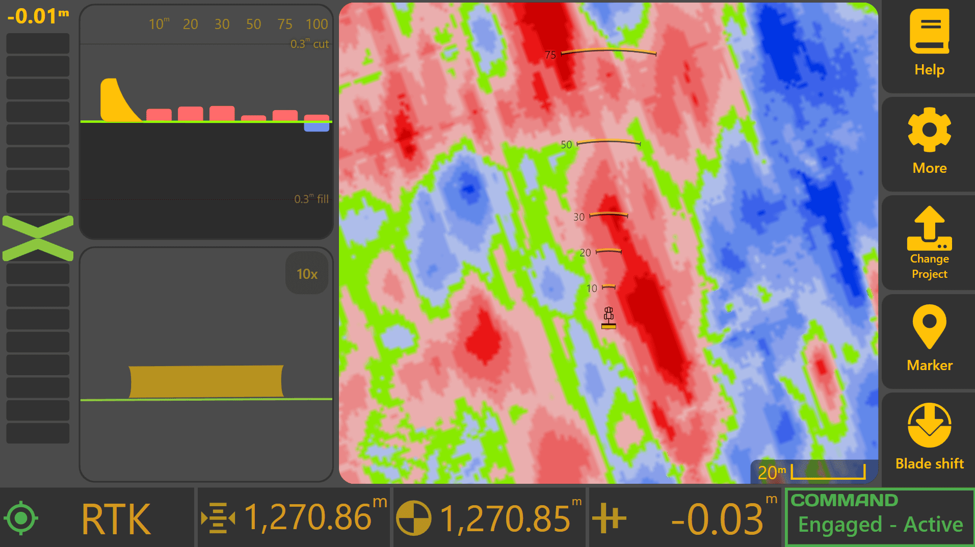
Important indicators include:
Error Chevron
The Error Chevron indicates whether the implement is above or below the design surface. As Automatic Control operates, the Error Chevron should generally move toward zero as the design elevation is approached.
Cross Section View
If using both Height and X-Slope control, monitor the Cross Section View to verify that both elevation and cross-fall are tracking correctly.
Cut/Fill Information
Monitor upcoming cut and fill values to understand how much material is approaching. Large cut or fill values may require a different operating strategy than smaller corrections.
Understanding the Control Profile
 The Control Profile provides a visual representation of the current Automatic Control target and implement position.
To display the Control Profile, press Blade Shift from the Apply View. The Control Profile will appear on the right side of the screen.
The profile displays:
Original
The original surveyed surface elevation.
Target
The elevation that Automatic Control is currently attempting to achieve.
Design
The final design elevation.
Current
The current measured implement elevation.
As Automatic Control operates, the Current position should generally move toward the Target position.
If Dynamic Cut Limit or Dynamic Fill Limit is active, the Target position may intentionally differ from the Design elevation. The shaded area of the Control Profile indicates material that will not be cut or filled during the current pass.
Using Blade Shift
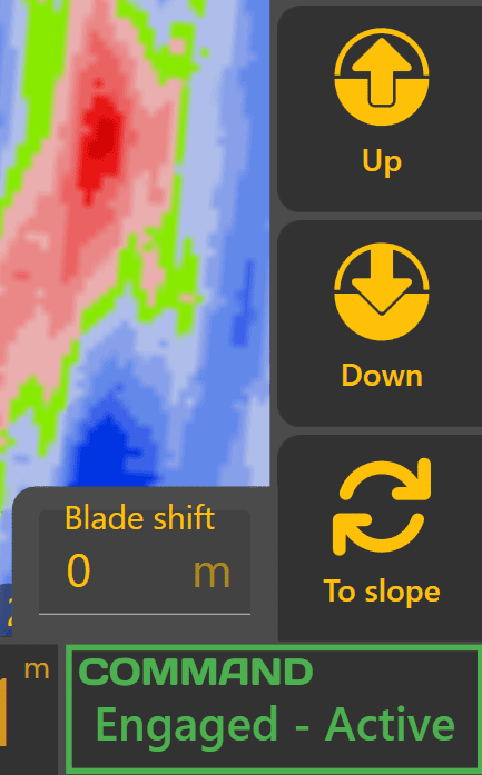
Blade Shift allows the operator to temporarily raise or lower the Automatic Control target without modifying the underlying design surface.
Use the Up and Down buttons to adjust the shift value.
Common uses include:
-
Leaving additional material for later trimming.
-
Reducing cutting depth during difficult conditions.
-
Making temporary grading adjustments without changing the design.
Blade Shift affects Automatic Control behaviour only and does not modify the design file.
Using Cut/Fill Limit
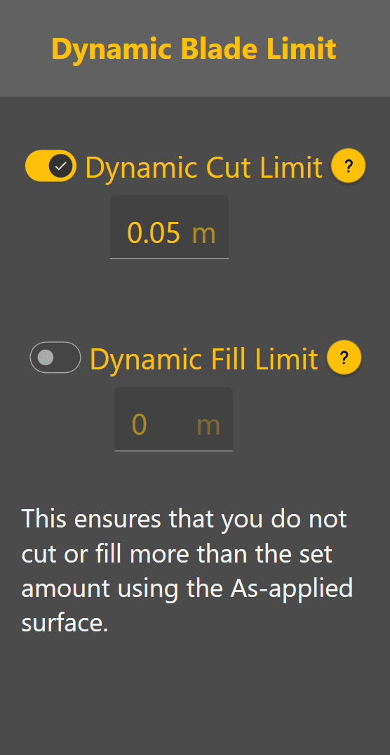
Cut/Fill Limiting allows Automatic Control to progressively work toward the design surface over multiple passes.
To access Cut/Fill Limiting:
-
Press Blade Shift.
-
Press Blade Limit.
-
Enable Dynamic Cut Limit and/or Dynamic Fill Limit.
-
Enter the desired limit value.
For example:
A Dynamic Cut Limit of 0.05 m will cause Automatic Control to target only 5 cm of cut during each pass, even if the full design requires a larger cut.
This can assist with:
-
Reducing blade loading.
-
Preventing machine overload.
-
Improving material control.
-
Maintaining smoother machine operation.
Multiple passes may be required to reach final grade when Cut/Fill Limiting is enabled.
Changing Surface Display Modes
Different map layers can be displayed depending on the information required.
Display settings can be changed from:
More → Appearance
Common display modes include:

Design
Displays the intended finished design surface.
 As Elevation

Displays the measured surface elevation collected during operation.
 As Cut/Fill
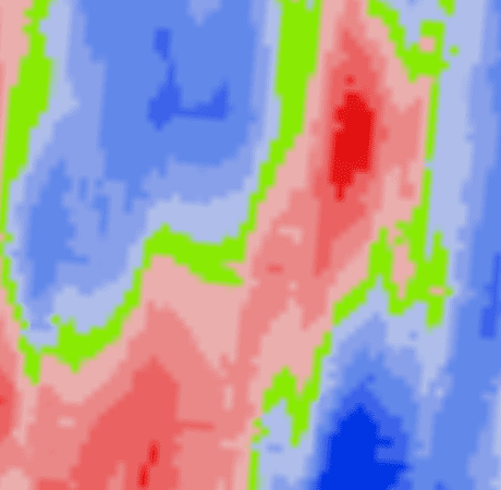
Displays current cut and fill values based on the latest surveyed surface.
The As Elevation and As Cut/Fill layers update dynamically as work progresses, making them useful for monitoring grading performance during operation.
Signs That Automatic Control Is Working Correctly
During normal operation:
-
The Error Chevron generally trends toward zero.
-
The Current value in the control profile moves toward the Target value.
-
The worked area updates on the map.
-
The finished surface visually matches the displayed cut/fill changes.
-
COMMAND Status remains Engaged - Active.
If Performance Appears Incorrect
If the implement appears slow to respond, struggles to reach grade or behaves erratically, verify that commissioning and calibration have been completed correctly.
Common causes include:
-
Incorrect valve calibration.
-
Hydraulic systems not placed into automatic mode.
-
Poor GNSS quality.
-
Tracking Sensitivity requiring adjustment.
Tracking Sensitivity controls the overall aggressiveness of Automatic Control:
-
Values that are too low may result in slow response and difficulty reaching target grade.
-
Values that are too high may result in excessive corrections and unstable implement movement.
If required, adjust Tracking Sensitivity in small increments and observe the resulting behaviour.
Verifying the Completed Pass
Once a pass has been completed, inspect both the worked surface and the map display. The completed area should generally show reduced cut/fill values and move closer to on-grade conditions. Multiple passes may be required where large cut or fill values are present.
In some situations, manual intervention may still be required to relocate material efficiently between cut and fill areas.
Confirming Surface Accuracy
Inspect the completed surface and check for:
-
Washboarding.
-
Dips.
-
High spots.
-
Surface irregularities.
If concerns remain about the accuracy of the completed work, a survey may be performed and compared against the updated surface displayed within Level COMMAND.
Ready to Continue
Once Automatic Control is producing smooth implement movement and the completed surface matches expectations, continue operating normally.
Refer to Chapter 5 for additional operational workflows and Chapter 6 for detailed information on Automatic Control behaviour. Continue on to 4.7 | Closing Level COMMAND.