The default **Tracking Threshold** and **Acquire Threshold** values are suitable for almost all applications and should not normally require adjustment. Modification of these parameters is generally not recommended.
Three operating regions are used: #### Tracking Region (e.g. < 10cm Error) The Tracking Region is the area immediately surrounding the design surface. This region provides the highest grading accuracy and is where the implement should spend most of its operating time. When the current error is within the configured **Tracking Threshold**, **COMMAND** continuously adjusts hydraulic output using its tracking control algorithm to accurately maintain the implement on grade. By default, the tracking threshold is 10cm for height functions, and 10 degrees for x-slope functions. Within the Tracking Region, hydraulic output is continuously adjusted between the calibrated minimum and maximum valve thresholds according to the current control error. #### Acquisition Region (e.g. > 10cm but < 1m Error) The Acquisition Region exists between the **Tracking Threshold** and **Acquire Threshold**. When the implement is outside the Tracking Region but remains within the **Acquire Threshold**, **COMMAND** prioritises returning the implement to the Tracking Region as quickly as possible. During acquisition, the ECU commands hydraulic output at the calibrated **Max %** threshold until the implement re-enters the Tracking Region. Once inside the Tracking Region, control automatically transitions back to normal tracking. #### Out of Range (e.g. > 1m Error) If the current error exceeds the configured **Acquire Threshold,** the implement is considered too far from the design surface for Automatic Control to operate safely or effectively. In this condition, **COMMAND** does not command hydraulic movement. This prevents large or unexpected hydraulic movements when the implement is significantly displaced from the design surface. The operator should manually reposition the implement closer to the design surface before Automatic Control resumes operation. ## Before Tuning [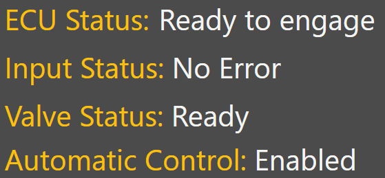](https://docs.t3rra.com/uploads/images/gallery/2025-08/xW68g0hjkQbD8asC-image.png) Before tuning, verify the following diagnostic indicators report normal operating status: - **COMMAND** ECU Status - Input Status - Valve Status - Automatic Control Diagnostics Any active faults or invalid status conditions should be corrected before tuning begins. ## Tuning Procedure ## [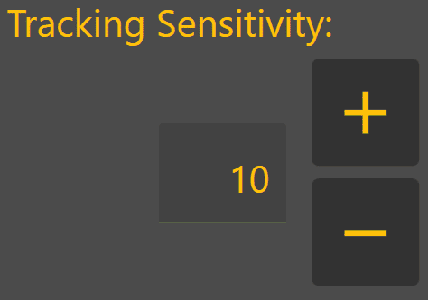](https://docs.t3rra.com/uploads/images/gallery/2025-08/3gRxv00W73mIGAJ2-image.png) Tuning should always be performed under normal working conditions using the same machine speed, hydraulic flow settings and operating practices that will be used during production work. **Level COMMAND** currently provides a single tuning parameter called **Tracking Sensitivity**. The objective is to achieve stable control while maintaining accurate tracking of the target surface. 1. Load a suitable project or design surface. 2. Engage Automatic Control. 3. Perform several passes under normal operating conditions. 4. Observe implement behaviour and control performance. 5. Adjust **Tracking Sensitivity** as required. 6. Repeat until the implement follows the target smoothly without excessive lag or oscillation. During normal grading, the implement should enter the Acquisition Region only briefly before returning to the Tracking Region, where it should remain for most of the grading operation. If the implement spends excessive time acquiring, overshoots repeatedly or oscillates around the target surface, further tuning may be required.| Adjustment | Typical Effect |
|---|---|
| Increase Tracking Sensitivity | Faster response, more aggressive control, increased risk of overshoot or oscillation. |
| Decrease Tracking Sensitivity | Slower response, smoother control, increased risk of lag and persistent tracking error. |
Correct [valve calibration](https://docs.t3rra.com/link/1147#bkmrk-minimum-threshold-%28m)—particularly the **Min** **%** thresholds—is essential before tuning begins. Incorrect **Min** **%** calibration can produce symptoms similar to incorrect **Tracking Sensitivity** and cannot be corrected through tuning alone.
#### Tracking Sensitivity Too Low - Implement responds slowly - **Current Error** remains visible for extended periods - Blade struggles to reach target grade - **DPF** remains elevated due to persistent tracking error Recommended Adjustment > Increase **Tracking Sensitivity**. [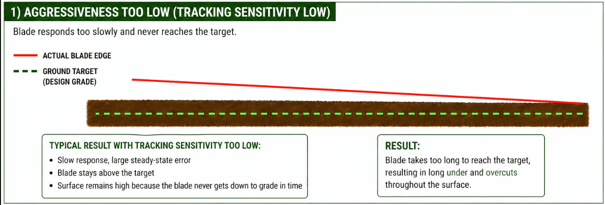](https://docs.t3rra.com/uploads/images/gallery/2026-06/zCOFaLwX6CtHlDpj-image.png) #### Tracking Sensitivity Too High - Implement reacts aggressively - Blade overshoots the target surface - Oscillation develops - **DPF** increases due to instability and overcorrection Reduce **Tracking Sensitivity**. Recommended Adjustment > Reduce **Tracking Sensitivity**. [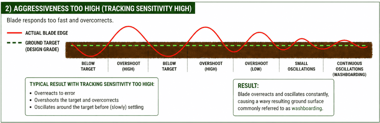](https://docs.t3rra.com/uploads/images/gallery/2026-06/k91zV9bYz3fcuqJi-image.png) Once Automatic Control is performing at an acceptable level, continue on to **3.9 | Validating System Operation**.