The **COMMAND** ECU will not request movement of the implement unless the user has pressed one of the test buttons and is holding the engage button.
1. Select the function and direction to calibrate. 2. Press **TEST** and hold the machine **ENGAGE** button when instructed. 3. Increase **Min. %** until the implement begins moving consistently at a very slow speed, e.g. about 1 centimetre per second. 4. Adjust **Max. %** as required: - For proportional solenoids, limit output to approximately **1800 mA**. - Reduce further if lower maximum implement speed is desired. 5. Repeat for all active directions and functions. #### Calibration Test Buttons The "+", "−" and "TEST" buttons are used during the calibration process to incrementally increase or reduce a given threshold, which can then be tested using the process described in the next section. #### Calibration Progress Icons This[](https://docs.t3rra.com/uploads/images/gallery/2025-08/8R3Nua9ds9TqSVa6-icon-uncalibrated.png) icon indicates that a value has not been calibrated yet. All minimum and maximum values for all active functions must be calibrated before performing automatic control. This [](https://docs.t3rra.com/uploads/images/gallery/2025-08/PdI75CypPWpfqpjF-icon-calibrated.png) icon indicates that a value has been calibrated. Once all min and max values display this icon, the function has been successfully calibrated.Ticks next to Min or Max values mean that the test button was pressed, but **do not indicate a correctly calibrated function**.
#### Example for Completed Height Function [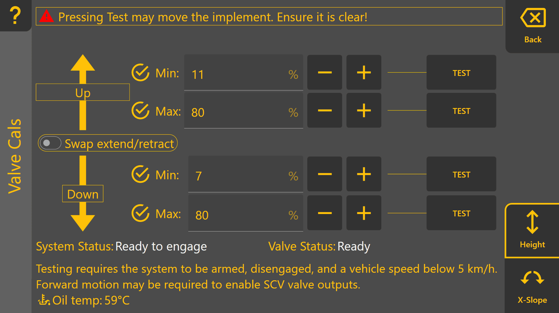](https://docs.t3rra.com/uploads/images/gallery/2026-06/I7RtWIj5rfmViFuw-image.png) #### Example for Completed X-Slope Function [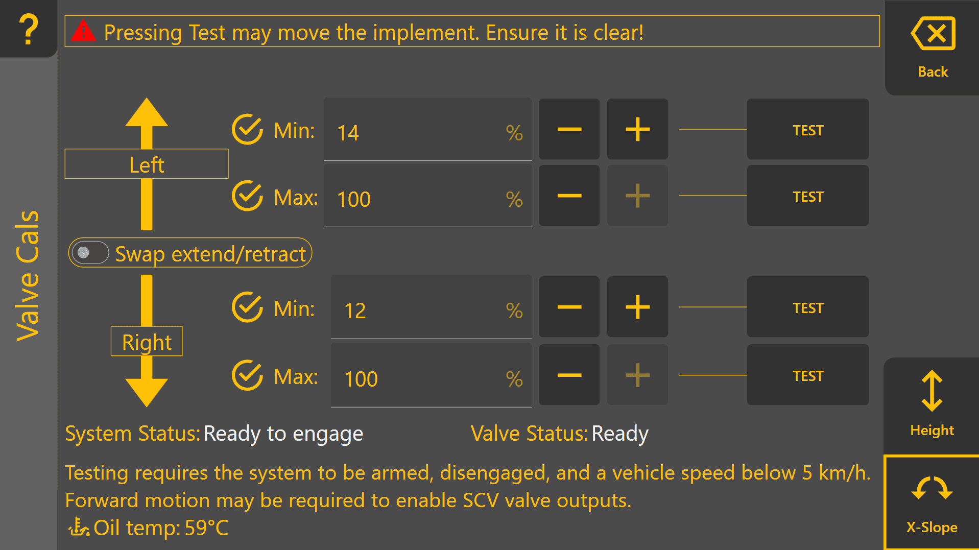](https://docs.t3rra.com/uploads/images/gallery/2026-06/OFVWGhCz3tIa1DHP-image.png) ## Verification Verify that: - Implement movement begins smoothly when Min % is tested. - No excessive delay or valve chatter occurs. - Full-speed movement is available when Max % is tested without hydraulic instability. - All calibration indicators show as complete before commissioning proceeds. Continue on to **3.7 | Cylinder Ratio Calibration**.