# 3.5 | Configuring Valve Outputs

[![image.png](https://docs.t3rra.com/uploads/images/gallery/2026-06/scaled-1680-/9uEsO89p0Nw2BAtu-image.png)](https://docs.t3rra.com/uploads/images/gallery/2026-06/9uEsO89p0Nw2BAtu-image.png)

The **Valve Configs** page is used to set up the control output interface for each control function. Appropriate signals of that interface type are then generated when automatic or manually controlling the implement. External joystick inputs are also configured on this page when making use of an analog or J1939 CANBUS joystick.

[![image.png](https://docs.t3rra.com/uploads/images/gallery/2026-06/scaled-1680-/OOdDozZSkAx6rcHT-image.png)](https://docs.t3rra.com/uploads/images/gallery/2026-06/OOdDozZSkAx6rcHT-image.png)

At the bottom right corner of the screen, buttons will be shown if there are two available control functions. If using a Height control only machine profile, only the Height page is displayed.

## Selecting the Valve Interface

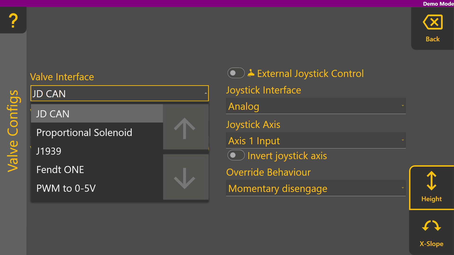
Select the appropriate **Valve Interface** for the tractor, machine or external valves being used for that function. To begin with, set the desired **Valve Interface** type for the Height control function.

<p class="callout info">Different **Valve Interface** selections display different **Valve Number** selections depending on how they work - for more information please see the section in the **COMMAND** manual.</p>

[![image.png](https://docs.t3rra.com/uploads/images/gallery/2025-08/scaled-1680-/CsyaCZMOhJtlnLtO-image.png)](https://docs.t3rra.com/uploads/images/gallery/2025-08/CsyaCZMOhJtlnLtO-image.png)

## Selecting the Valve Number

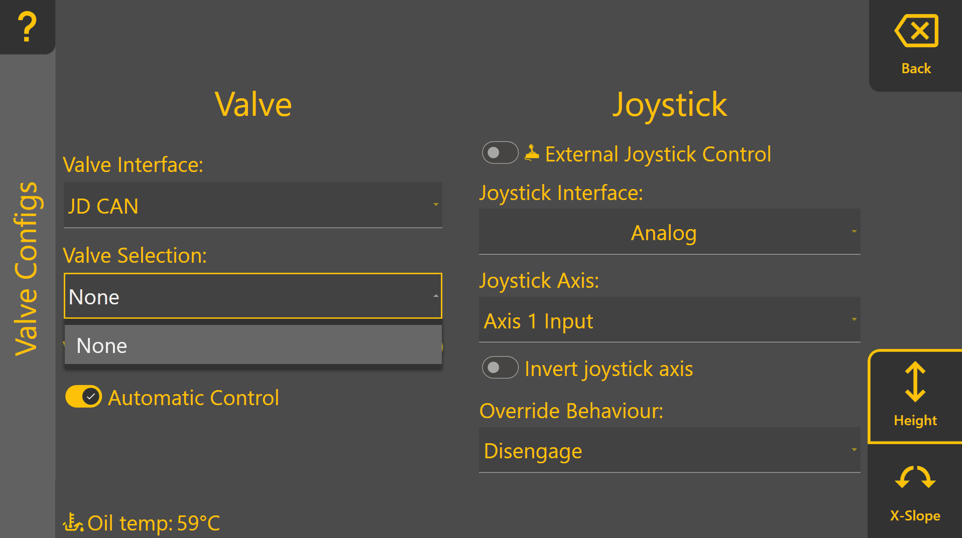
When selecting **Valve Interface** options like JD CAN, J1939 and Fendt ONE will only display valve numbers that have been detected on the ISOBUS or machine CANBUS. Below shows an example of the dropdown with the tractor switched off.

[![image.png](https://docs.t3rra.com/uploads/images/gallery/2026-06/scaled-1680-/vJVspAPIEaaHEpaz-image.png)](https://docs.t3rra.com/uploads/images/gallery/2026-06/vJVspAPIEaaHEpaz-image.png)
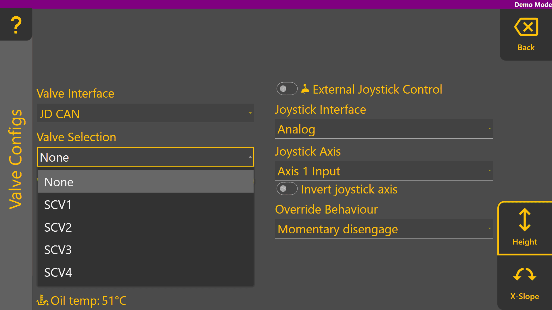
Once detected on the ISOBUS or machine CANBUS, any available SCV / Remote / Auxiliary valve selections will be displayed in the **Valve Selection** list as shown:

[![image.png](https://docs.t3rra.com/uploads/images/gallery/2025-08/scaled-1680-/Z1rpwjhhDtPDhwEv-image.png)](https://docs.t3rra.com/uploads/images/gallery/2025-08/Z1rpwjhhDtPDhwEv-image.png)
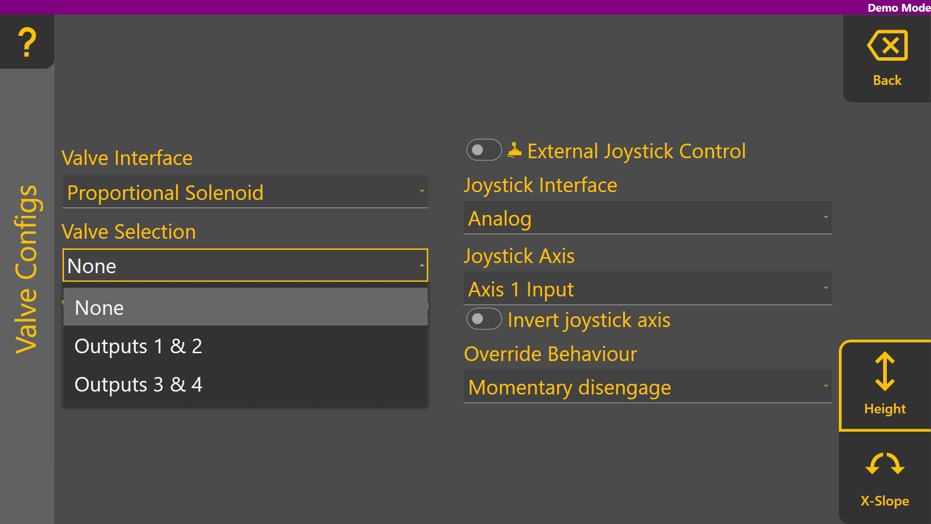
Analog valve interfaces such as Proportional Solenoid and PWM to 0-5V always display all available **Valve Selection** options. Valve signals for these selections generally rely on harnessing to connect the outputs of the **COMMAND** ECU to the proportional solenoid or laser system inputs.

[![image.png](https://docs.t3rra.com/uploads/images/gallery/2025-08/scaled-1680-/wmEjkiD9uWjcxzmQ-image.png)](https://docs.t3rra.com/uploads/images/gallery/2025-08/wmEjkiD9uWjcxzmQ-image.png)
## Valve Status

**Valve Status** provides information on the current status of the selected **Valve Interface** and **Valve Selection**. The table below explains each of the different possible valve statuses that may appear:

<table id="bkmrk-status-description-v" style="border-collapse: collapse; width: 100%; height: 620.25px;"><colgroup><col style="width: 30.395%;"></col><col style="width: 69.5255%;"></col></colgroup><tbody><tr style="height: 30.125px;"><td style="height: 30.125px;">**Status**</td><td style="height: 30.125px;">**Description**</td></tr><tr style="height: 46.9167px;"><td style="height: 46.9167px;">Valve Unavailable</td><td style="height: 46.9167px;">The selected valve is not available for use.

</td></tr><tr style="height: 63.7083px;"><td style="height: 63.7083px;">Waiting for Manual SCV Input</td><td style="height: 63.7083px;">Move the SCV lever corresponding to the selected SCV - this must be done when using John Deere tractors.

</td></tr><tr style="height: 63.7083px;"><td style="height: 63.7083px;">Short to Ground</td><td style="height: 63.7083px;">An overload has been detected and the resistance between the valve signal output pin and ground is near-zero, holding the output low.

</td></tr><tr style="height: 63.7083px;"><td style="height: 63.7083px;">Short to Batt</td><td style="height: 63.7083px;">An overload has been detected and the valve signal output pin is being fed power from another source holding the output high.

</td></tr><tr style="height: 63.7083px;"><td style="height: 63.7083px;">Open Load</td><td style="height: 63.7083px;">A connection or valve issue has been detected, and the resistance between valve signal output pin is too high, indicating a broken wire or valve solenoid/coil.

</td></tr><tr style="height: 46.9167px;"><td style="height: 46.9167px;">SCVs Locked</td><td style="height: 46.9167px;">The SCVs must be unlocked using the console SCV padlock button.

</td></tr><tr style="height: 177.75px;"><td style="height: 177.75px;">System Not Armed</td><td style="height: 177.75px;">The **COMMAND** Arm/Engage switch must be armed or re-armed.

If the Arm/Engage switch is currently Off:

- Switch the Arm/Engage switch to the middle position.

If the Arm/Engage switch is currently in the middle position:

- Switch the Arm/Engage switch to the OFF position, and then back to the middle position.

</td></tr><tr style="height: 63.7083px;"><td style="height: 63.7083px;">Ready</td><td style="height: 63.7083px;">The selected valve is currently not active and the ECU is ready for automatic control or manual control commands for that function.

</td></tr></tbody></table>

## External Joystick Setup

Settings related to external joystick inputs for each function can also be found on this page. Enable external joystick control for each function using the toggle shown below. Once **External Joystick Control** has been enabled, the **COMMAND** ECU will begin using the selected **Joystick Interface** and **Joystick Axis** for manual implement control.

[![image.png](https://docs.t3rra.com/uploads/images/gallery/2025-08/scaled-1680-/6zbPF2PbD8DWCDMH-image.png)](https://docs.t3rra.com/uploads/images/gallery/2025-08/6zbPF2PbD8DWCDMH-image.png)

#### Selecting the Joystick Interface

Select the appropriate **Joystick Interface** for the Height function, depending on the joystick being used:

- If using an analog voltage based joystick, select "Analog"
- If using a J1939 CANBUS based joystick, select "J1939"

[![image.png](https://docs.t3rra.com/uploads/images/gallery/2026-06/scaled-1680-/0bFQtizd9EpwJZB9-image.png)](https://docs.t3rra.com/uploads/images/gallery/2026-06/0bFQtizd9EpwJZB9-image.png)

#### Selecting the Joystick Axis (Analog)

Next, select the appropriate **Joystick Axis**. For the Analog interface, Axis 1 is intended for the joystick Y-axis, Axis 2 is intended for the joystick X-axis and Axis 3 is intended for the joystick Z-axis if present.

[![image.png](https://docs.t3rra.com/uploads/images/gallery/2026-06/scaled-1680-/G5DEJ6Hj0bh2d463-image.png)](https://docs.t3rra.com/uploads/images/gallery/2026-06/G5DEJ6Hj0bh2d463-image.png)

#### Selecting the Joystick Interface (J1939 / CAN)

For the J1939 interface, select the joystick axis to be used for the function, e.g. Y-axis for manual height control.

[![image.png](https://docs.t3rra.com/uploads/images/gallery/2026-06/scaled-1680-/oERuzJK99dyU1Scw-image.png)](https://docs.t3rra.com/uploads/images/gallery/2026-06/oERuzJK99dyU1Scw-image.png)

#### Swapping the Joystick Axis' Control Direction

If moving the joystick in a certain direction causes the wrong physical movement direction, the axis can be inverted using the **Invert Joystick Axis** toggle.

[![image.png](https://docs.t3rra.com/uploads/images/gallery/2025-08/scaled-1680-/tZCpqtw8Q7kPc5q9-image.png)](https://docs.t3rra.com/uploads/images/gallery/2025-08/tZCpqtw8Q7kPc5q9-image.png)

#### Selecting the Override Behaviour

Lastly, select the desired **Override Behaviour** for the function:

- "Disengage" will cause any joystick movement to disengage automatic control mode, requiring the operator to press the engage button again to resume automatic control.
- "Momentary Disengage" will cause any joystick movement to only momentarily disengage automatic control mode. Once the joystick is no longer being moved, **COMMAND** will resume controlling the implement automatically.

<p class="callout info">Regardless of **Override Behaviour** selection, **COMMAND** will always prioritise joystick/manual control signals over automatic control signals to maintain full operator control of the implement.</p>

[![image.png](https://docs.t3rra.com/uploads/images/gallery/2026-06/scaled-1680-/nNQwrwdSyaPstVDg-image.png)](https://docs.t3rra.com/uploads/images/gallery/2026-06/nNQwrwdSyaPstVDg-image.png)

#### Example Height Valve Configuration Page

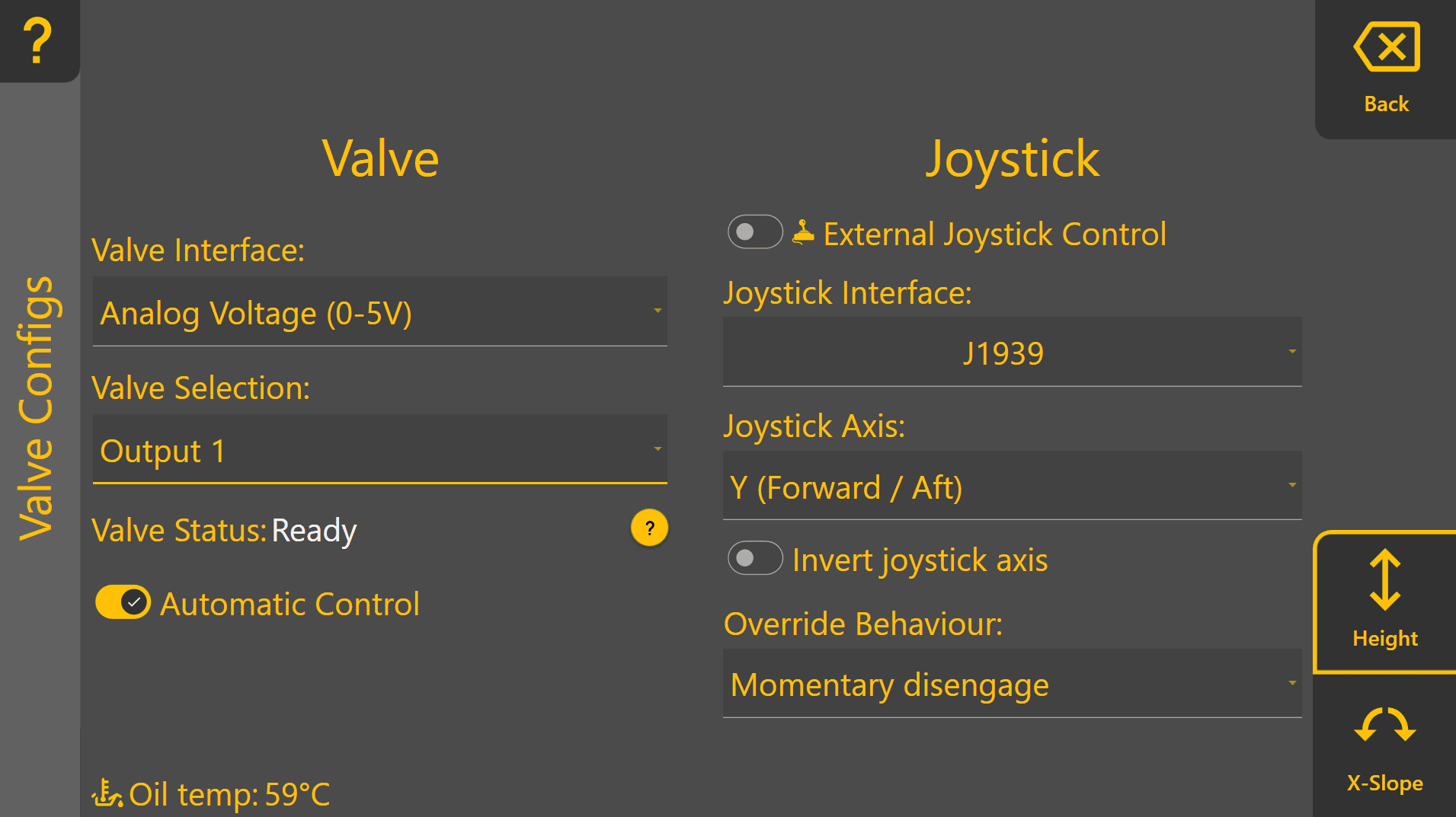
Below shows an example of a configuration using PWM to 0-5V **Valve Interface**, using the **T3H-V001** valve adapter on Output 1, with **Automatic Control** enabled. **External Joystick Control** has also been enabled for use with a J1939 CANBUS joystick, with the Y-axis controlling the Height function and will momentarily disengage automatic control when the joystick is moved.

[![image.png](https://docs.t3rra.com/uploads/images/gallery/2026-06/scaled-1680-/J3NTkoYgKZNqd3Va-image.png)](https://docs.t3rra.com/uploads/images/gallery/2026-06/J3NTkoYgKZNqd3Va-image.png)
#### Example X-Slope Valve Configuration Page

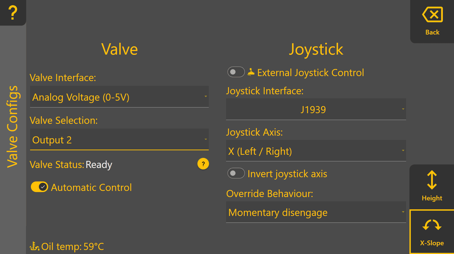
Swapping over to the X-Slope function using the bottom right button, an example configuration shown below is set up to use PWM to 0-5V **Valve Interface**, using the T3H-V001 adapter on Output 2. X-Slope is enabled for automatic control, and also has External Joystick Control enabled for use with a J1939 CANBUS joystick on the X-axis, momentarily disengaging when the operator moves the joystick.

[![image.png](https://docs.t3rra.com/uploads/images/gallery/2026-06/scaled-1680-/8qfvbowzlQLf2rcz-image.png)](https://docs.t3rra.com/uploads/images/gallery/2026-06/8qfvbowzlQLf2rcz-image.png)
Press "**Back**" to return to the COMMAND Settings Overview page and continue on to **3.6 | Valve Threshold Calibration**.