Level COMMAND Manual (EN)
Get moving dirt with the machine you know best. Purpose-built to get you working faster, with fewer hassles.
- 1 | Introduction
- 1.1 | Title
- 1.2 | About Level COMMAND
- 1.3 | Intended Use
- 1.4 | Important Notices
- 1.5 | Operator Responsibilities
- 1.6 | Important Safety Information
- 1.7 | Terminology & Definitions
- 2 | System Overview
- 2.1 | System Architecture
- 2.2 | Supported Machine Configurations (Profiles)
- 2.3 | Positioning & Sensor Requirements
- 2.4 | Hydraulic & Vehicle Interfaces
- 2.5 | System Components
- 3 | Dealer Installation & Commissioning
- 3.1 | Connecting to the COMMAND ECU
- 3.2 | Checking for Software & Firmware Updates
- 3.3 | Selecting A Machine Profile
- 3.4 | Configuring GNSS
- 3.5 | Configuring Valve Outputs
- 3.6 | Valve Threshold Calibration
- 3.7 | Cylinder Ratio Calibration
- 3.8 | Tuning Automatic Implement Control
- 3.9 | Validating System Operation
- 4 | Operator Quick Start
- 4.1 | System Startup
- 4.2 | Understanding COMMAND Status
- 4.3 | Loading or Creating a Project
- 4.4 | Setting Zero
- 4.5 | Engaging Automatic Control
- 4.6 | Performing Your First Pass
- 4.7 | Closing Level COMMAND
- 5 | Operational Workflows
- 5.1 | Apply View Overview
- 5.2 | Apply View Layout
- 5.3 | Widget Customisation
- 5.4 | Plane Projects & Surface Creation
- 5.5 | Pre-designed Projects & Data
- 5.6 | Surveying & Field Data Collection
- 5.7 | Markers & Benchmarks
- 5.8 | Choosing a Zeroing Method
- 6 | Automatic Control & Surface Behaviour
- 6.1 | Understanding Surface Layers
- 6.2 | Automatic Blade Control
- 6.3 | Blade Control Modes
- 6.4 | Blade Shift & Target Adjustment
- 6.5 | Reliable Positioning
- 6.6 | Automatic Control Tuning
- 6.7 | Look Ahead
- 6.8 | Tandem Blade Behaviour
- 7 | Settings & Preferences
- 7.1 | Appearance
- 7.2 | Units
- 7.3 | Language & Accessibility
- 7.4 | Updates & Release Management
- 7.5 | Licensing
- 7.6 | Support & Error Reporting
- 7.7 | Diagnostics / Advanced
- Appendix A | COMMAND Settings Reference
1 | Introduction
1.1 | Title
Operation & User Manual

2026
1.2 | About Level COMMAND
Level COMMAND (LC) is a GNSS-based machine control software operating environment developed by T3RRA for construction, earthmoving, and landforming machinery.
Operating together with the COMMAND hardware platform, Level COMMAND provides terrain visualisation, machine positioning, surface guidance, and automatic implement control for supported machine configurations.
Level COMMAND combines GNSS positioning, machine sensors, hydraulic control interfaces, and project design data to assist operators in achieving accurate terrain outcomes during grading and earthmoving operations.
Depending on machine configuration and enabled features, Level COMMAND may support:
- Terrain guidance
- Automatic blade control
- Plane and surface workflows
- Terrain surveying
- Benchmark and zeroing workflows
- Surface visualisation and cut/fill mapping
This manual describes operational workflows, machine-control concepts, commissioning procedures, calibration functions, and diagnostic tools associated with the Level COMMAND system.
1.3 | Intended Use
Level COMMAND is intended for use on supported construction, landforming, and earthmoving machinery equipped with compatible COMMAND hardware, GNSS receivers, hydraulic interfaces, and machine sensors.
The system is designed to assist operators with terrain guidance, grading operations, surface control, and automatic implement positioning during earthmoving and landforming activities.
System performance depends on:
- correct installation
- machine calibration
- GNSS signal quality
- terrain conditions
- hydraulic performance
- and operator supervision
Level COMMAND is an operator-assistance and terrain-control system. The operator remains responsible for safe machine operation, terrain awareness, and final work quality at all times.
The system must only be operated by personnel familiar with machine-control systems and safe equipment operating procedures.
1.4 | Important Notices
Level COMMAND Operators Manual
© 2026 T3RRA
Notice of Rights
No part of this publication may be reproduced, transmitted, transcribed, stored in a retrieval system, or translated into any language or computer language, in any form or by any means, electronic, mechanical, magnetic, optical, chemical, manual, or otherwise, without the prior written permission of T3RRA Pty Ltd.
Trademark Notice
T3RRA Cutta™, T3RRA Plane™, T3RRA Ditch™, T3RRA Survey™, T3RRA Apply™, COMMAND™ and Level COMMAND™ software images and their logos are the exclusive trademarks of T3RRA. All other trademarks, service marks, software images and logos used in this documentation belong to their respective owners.
Notice of Liability
The information in this document is distributed on an ‘as is’ basis, without warranty. While every precaution has been taken in the preparation of this manual, neither the authors nor T3RRA shall have any liability to any person or entity with respect to any loss or damage caused or alleged to be caused directly or indirectly by the instructions contained in this book or by the machine-control systems and associated equipment products described in it.
Disclaimer
We make a sincere effort to ensure the accuracy of the material described herein; however, T3RRA makes no warranty, expressed or implied, with respect to the quality, correctness, reliability, accuracy, or freedom from error of this document or the products it describes. Data used in examples and sample data files are intended to be fictional. Any resemblance to real persons or companies is entirely coincidental. While reasonable effort has been made to ensure the accuracy of this publication, T3RRA assumes no responsibility for errors or omissions, or for damages resulting from use of the information contained within this manual. Information contained within this manual was current at the time of publication.
1.5 | Operator Responsibilities
System Usage
The COMMAND hardware platform and Level COMMAND operating environment must only be installed, commissioned, and operated by personnel familiar with machine-control systems and associated safety procedures.
Any safety warnings or images used in this manual should be closely observed to ensure safe usage of the COMMAND and Level COMMAND system. If any information provided in this manual is not understood by the technician or operator, they must contact T3RRA prior to usage of the system.
Operators are responsible for verifying correct system setup, terrain alignment, project selection, and machine response before engaging automatic control.
Prior to operation, verify:
- machine calibration,
- active project data,
- benchmark alignment,
- GNSS quality,
- and hydraulic response.
Automatic control functions should only be engaged after confirming safe and predictable implement movement. Operators must remain aware of terrain conditions, nearby personnel, and machine behaviour at all times during operation.
Technical Support
For technical support associated with COMMAND or Level COMMAND, please contact your authorised T3RRA dealer.
1.6 | Important Safety Information
General Safety Guidelines
Read and Understand Instructions
Operators must read this manual in full before using the system. Do not operate the system without a complete understanding of its controls and functions.
Authorized Personnel Only
Only trained and qualified individuals should operate, maintain, or service the Level COMMAND system.
Operator Responsibility
Level COMMAND is designed to assist with terrain-control and grading operations but does not replace operator supervision. The operator must remain alert and in control at all times.
Operational Safety
Supervise All Automated Movements
The implement may move automatically in response to terrain, sensor or control inputs.
Maintain Safe Distance
Never stand or allow others to stand near the implement, or hydraulic components while the system is engaged.
Manual Override
Ensure all operators are familiar with how to disengage or manually override the system in an emergency.
System Activation Warnings
Automatic Movement Hazards
The implement may move without manual input during automatic operation. Clear the area of personnel before activating the system.
Hydraulic Pressure Hazards
This system operates using high-pressure hydraulic components. Do not inspect, service, or disconnect hydraulic lines while the system is active or pressurized. Use caution when working near hoses and actuators.
Sensor and Signal Dependency
GNSS Dependency
The system relies on accurate GNSS input data. A degraded or lost signal can lead to incorrect implement height or tilt adjustments.
IMU Sensor Calibration
Degraded sensor data may cause unintended implement movement.
Terrain and Environmental Awareness
Inspect Field Conditions
The system cannot detect soft ground, underground obstacles, ditches, or debris. Manually inspect and clear the field before use.
Slope Limits
Avoid operating the system on steep or uneven terrain beyond rated slope specifications. Excessive tilt may cause tipping or unsafe implement engagement.
Maintenance Safety
Pre-Start Inspection
Before each operation, inspect all components, including hydraulic lines, sensor mounts, and electrical connections.
Lockout/Tagout for Servicing
Fully power down the tractor and disable the land levelling system before performing any maintenance.
Emergency Protocols
Emergency Stop
Ensure the operator is aware of the emergency stop mechanism location and function. Adhere to Tractor/Machinery emergency stop protocols and testing requirements.
Error Handling
If the system displays a fault code, sensor error, or warning alert, cease operation immediately and refer to the Troubleshooting section.
Bystander & Site Safety
No Passengers
Never allow anyone to ride on the implement or tractor while the system is operating.
Establish Exclusion Zone
Mark the working area clearly. Unauthorized personnel should remain clear of the worksite during automated operations.
Safety Labelling
Ensure all safety labels on the implement and control interface are clean, visible, and intact. Replace damaged or unreadable labels immediately.
1.7 | Terminology & Definitions
Armed
Automatic control is enabled and ready to assume implement control when engagement conditions are met.
Benchmark
A known reference position or elevation used to align or verify machine position relative to the active project or terrain surface.
Blade Shift
A temporary adjustment applied to blade height or cross-slope relative to the active design surface without modifying the underlying project data.
Control Mode
The active automatic control strategy used to determine how the implement responds relative to the target surface or terrain.
Current Height
The measured elevation of the controlled point at the machine’s current position.
Design Height
The elevation defined by the active project surface or plane at the machine’s current position.
Engaged
Automatic implement control is actively controlling hydraulic output to achieve the target surface or control objective.
GNSS
Look Ahead
A predictive control function that anticipates upcoming terrain changes and adjusts implement response to improve surface accuracy and machine stability.
Marker
A user-defined reference point stored within a project for operational, surveying, or alignment purposes.
Original Height
The measured terrain elevation recorded before material movement or grading operations occur.
Plane
A mathematically defined flat grading surface generated using slope, elevation, and orientation parameters.
Position Quality
The estimated reliability of GNSS and sensor data used for terrain positioning and automatic control functions.
Project
The collection of surfaces, planes, linework, markers, terrain data, and operational settings associated with a worksite or job.
Surface
A terrain model or design representation used for guidance, visualisation, and automatic implement control.
Target Height
The elevation the system is attempting to achieve at the controlled point relative to the active surface or control mode.
Terrain Alignment
The process of aligning machine position and elevation relative to known terrain references, benchmarks, or project coordinates.
Zero
A positional or elevation offset applied to align the machine with known terrain or project reference data.
2 | System Overview
Level COMMAND is an integrated machine guidance and control system designed to provide real-time positioning, terrain visualisation, and machine control functionality for supported earthmoving equipment.
2.1 | System Architecture
Level COMMAND continuously determines the machine's position, compares it to the design surface and calculates the implement movement required to achieve the desired grade.
Theory of Operation
Level COMMAND is a closed-loop terrain-control operating environment that continuously compares the machine’s measured terrain position against the active design surface or plane in order to determine the required implement movement.
The system operates together with the COMMAND hardware platform, GNSS receivers, hydraulic interfaces, machine sensors, and operator inputs to provide terrain guidance and automatic implement control.
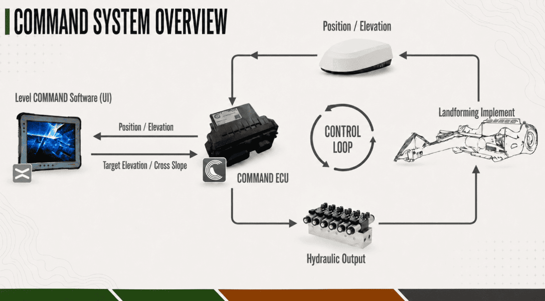
During operation, Level COMMAND continuously processes:
- GNSS position data
- Machine and receiver offsets
- Active design surfaces or planes
- Machine configuration information
- Operator-applied offsets and limits
- Vehicle movement and speed information
Using this information, the system calculates target elevations and control corrections which are transmitted to the COMMAND ECU for hydraulic or vehicle interface control.
The operator remains responsible for supervising machine behaviour and safe operation at all times.
Position & Elevation Processing
GNSS receivers are mounted at known positions relative to the controlled implement. Level COMMAND applies configured machine and receiver offsets to calculate the position of the controlled point relative to the terrain surface.
Using the calculated controlled-point position, the system determines:
- Current Height
- Design Height
- Target Height
- Cross-slope or tilt requirements where applicable
These values are used to determine the required implement correction relative to the active design surface or control mode.
Configured machine geometry and positional offsets are applied before hydraulic commands are transmitted to the COMMAND ECU to ensure implement movement corresponds correctly to the controlled point position.
Predictive Control (Look Ahead)
Hydraulic systems and machine movement introduce a delay between terrain measurement and implement response.
To improve grading accuracy during movement, the system uses predictive positioning behaviour referred to as Look Ahead.
Look Ahead estimates the future position of the controlled point based on current machine speed and configurable control response timing. Target elevations are then calculated ahead of the machine’s current position to reduce tracking lag and improve terrain-following performance.
Look Ahead settings may be adjusted during commissioning and advanced diagnostics procedures.
Blade Shift & Control Limits
Material movement requirements may exceed the desired cut or fill amount achievable in a single grading pass.
Blade Shift allows operators to temporarily offset the target elevation relative to the active design surface without modifying the underlying project data.
Additional control limits may also be applied to restrict:
- Maximum cut depth
- Maximum fill height
- Cross-slope correction
- Hydraulic response behaviour
- Automatic control engagement conditions
These limits assist in maintaining stable machine behaviour and predictable terrain outcomes during automatic control operation.
Off-Surface Behaviour
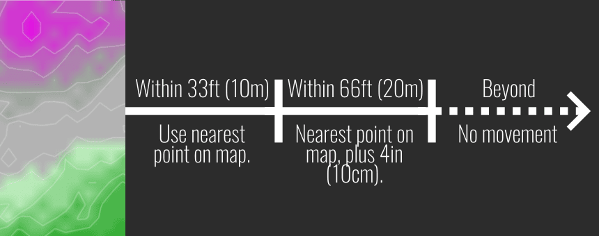
Automatic control operation requires valid design surface data. If the machine moves outside the available design surface area, the system may suspend automatic control movement commands until valid surface data becomes available again. Automatic control resumes as the implement approaches the design surface again.
This behaviour prevents unintended implement movement when operating beyond the active design boundary.
Manual & Automatic Control Modes
Level COMMAND supports both manual and automatic implement control operation.
Manual Control Mode
When automatic control is Disengaged, hydraulic movement remains under direct operator control using tractor SCVs, joysticks, or other configured control inputs.
In Manual Control Mode, the system continues to display terrain, project, and elevation information but does not actively control hydraulic outputs.
Armed State
When the system is Armed, the COMMAND ECU is enabled and prepared to assume automatic control once engagement conditions are satisfied.
While Armed, manual hydraulic control remains available to the operator. The Armed state allows the system to monitor positioning and control conditions while preventing automatic hydraulic actuation until automatic control is Engaged.
Automatic Control Mode
When automatic control is Engaged, the system continuously calculates implement corrections relative to the active design surface or plane.
The COMMAND ECU then controls hydraulic outputs using:
- Current terrain position
- Target elevation
- Cross-slope targets where applicable
- Control calibration parameters
- Tracking sensitivity settings
- Acquire and tracking thresholds
Depending on machine configuration, manual hydraulic input may temporarily override automatic control or disengage automatic control operation. Automatic control may be disengaged at any time using the configured disengagement controls or Arm/Engage switch.
2.2 | Supported Machine Configurations (Profiles)
Level COMMAND supports multiple machine configurations depending on machine type, hydraulic capability, installed hardware, and available automatic control functions.
Each machine configuration defines the supported automatic control functions and compatible machine architecture for the connected implement.
Available machine configurations may vary depending on installed hardware, software licensing, and machine compatibility.
Single Scraper — Height
The Single Scraper — Height profile provides automatic height control for supported single-channel scraper configurations.
Typical applications include:
- landforming,
- scraper levelling,
- and general earthmoving operations.
Single Scraper — Height & XSlope
The Single Scraper — Height & XSlope profile provides automatic height and Cross-Slope control for supported dual-channel scraper configurations.
Typical applications include:
- precision grading,
- drainage shaping,
- and controlled Cross-Slope operations.
This configuration requires compatible Cross-Slope sensing hardware.
Single Ditcher — Height
The Single Ditcher — Height profile provides automatic height control for supported ditching and channel-forming implements.
Typical applications include:
- drainage channel construction,
- irrigation works,
- and ditch grading operations.
Future Configuration Support
Additional machine configurations and automatic control capabilities may become available in future Level COMMAND releases depending on machine compatibility and installed hardware support.
2.3 | Positioning & Sensor Requirements
Level COMMAND uses GNSS positioning data, machine geometry information, and implement orientation feedback to calculate target elevations and automatic control corrections.
Depending on machine configuration and enabled functions, the system may require:
- RTK GNSS positioning,
- vehicle heading information,
- Cross-Slope feedback,
- machine geometry offsets,
- and compatible COMMAND hardware interfaces.
GNSS Positioning Requirements
Level COMMAND receives GNSS positioning information through the COMMAND ECU.
GNSS positioning data is used to determine machine location, implement elevation, and terrain position relative to the active design surface or plane.
Automatic control operation requires stable RTK-quality positioning suitable for precision terrain-control applications.
If GNSS quality falls outside configured operating limits, automatic control operation may be restricted or disengaged.
Heading Information
Vehicle heading information is used to determine machine movement direction relative to the active terrain design.
Heading information is typically supplied through GNSS data received by the COMMAND ECU.
If dedicated heading information is unavailable, the system may determine movement direction using positional change during vehicle movement.
Cross-Slope Feedback
Machine configurations supporting automatic Cross-Slope control require compatible implement roll-angle feedback.
Cross-Slope feedback is used to determine implement orientation relative to the active design surface and commanded Cross-Slope target.
Supported Cross-Slope feedback sources currently include:
- T3RRA TARS IMU systems,
- and compatible StarFire internal roll-angle sensors.
Invalid or unstable Cross-Slope data may prevent automatic control engagement or cause automatic control disengagement.
Machine Geometry & Offsets
Level COMMAND uses configurable machine geometry information to calculate implement position relative to the GNSS receiver location.
Depending on machine configuration, offsets may include:
- sensor height offset,
- lateral offset,
- and fore/aft offset.
Incorrect machine geometry configuration may result in inaccurate implement positioning or automatic control behaviour.
Sensor Stability & Control Protection
The COMMAND hardware platform continuously monitors positioning and sensor information during operation.
Automatic control engagement may be prevented, or automatic control may disengage, if:
- GNSS positioning becomes invalid,
- sensor information becomes unstable,
- positioning changes exceed configured operating limits,
- hydraulic faults are detected,
- or operating conditions fall outside configured control thresholds.
These protections assist in maintaining predictable implement behaviour during automatic control operation.
2.4 | Hydraulic & Vehicle Interfaces
The COMMAND hardware platform supports multiple hydraulic and vehicle interface methods depending on machine configuration, installed COMMAND hardware, and enabled automatic control functions.
These interfaces allow COMMAND to control implement movement and monitor machine information during automatic control.
Hydraulic Control Interfaces
Depending on machine configuration, COMMAND may support:
- single-channel height control,
- dual-channel height and Cross-Slope control,
- and implement-specific hydraulic functions.
Supported hydraulic interface methods may include:
- Selectable Control Valves (SCVs) / auxiliary control valves,
- proportional solenoid valves,
- and ratiometric load sensing proportional valves.
Hydraulic outputs are used by COMMAND to change implement position during automatic control based on elevation and Cross-Slope targets provided by Level COMMAND.
Vehicle Data Interfaces
COMMAND may receive vehicle and machine information using compatible communication interfaces.
Supported interface methods may include:
- J1939 vehicle communication,
- CANBUS communication,
- and supported OEM machine data interfaces.
Available machine data may include:
- vehicle speed,
- hydraulic state information,
- and supported machine sensor information.
Available interface methods may vary depending on installed COMMAND hardware and machine compatibility.
Manual Hydraulic Operation
Manual hydraulic operation remains available whether automatic control is Engaged or Disengaged.
Depending on machine configuration, manual implement control may be performed using:
- tractor SCVs,
- joysticks,
- external hydraulic controls,
- or OEM machine hydraulic controls.
The Armed state enables the COMMAND ECU while preventing automatic hydraulic actuation until automatic control is Engaged.
Disarming the COMMAND ECU will disengage automatic control and disable joystick inputs connected directly through COMMAND. Tractor-level SCV lever and joystick operation remain unaffected.
2.5 | System Components
A Level COMMAND system consists of multiple hardware and software components depending on machine configuration and enabled automatic control functions.
Required Components
The following components are required for normal Level COMMAND operation.
COMMAND ECU
The COMMAND ECU provides hydraulic control, machine interfacing, sensor monitoring, and automatic control management.
The ECU communicates with Level COMMAND and connected machine systems during operation.
GNSS Receiver System
A compatible RTK-capable GNSS receiver system is required for machine positioning and automatic control.
Supported receiver compatibility may vary depending on installed COMMAND hardware and machine configuration.
Operator Display Device
Level COMMAND operates on a compatible display device used for:
- project management
- terrain visualisation
- diagnostics
- and operator interaction
The display device communicates with the COMMAND ECU during operation.
Level COMMAND is primarily deployed on ruggedised RuggON tablet platforms including the PX501 and SOL7 due to their environmental durability, sunlight readability, and suitability for machine-control applications.
Hydraulic Control Hardware
Compatible hydraulic control valve hardware is required for automatic implement movement.
Depending on machine configuration, hydraulic interfaces may include:
- SCVs / auxiliary control valves
- proportional solenoid valves
- and ratiometric load sensing proportional valves
Optional Components
Additional components may be installed depending on machine configuration and enabled functionality.
Cross-Slope Sensors
Cross-Slope-capable configurations require compatible implement roll-angle feedback sensors.
Supported Cross-Slope feedback sources currently include:
- T3RRA TARS IMU systems
- and compatible StarFire internal roll-angle sensors
Additional Operator Controls
Optional operator control devices may include:
- External Engage switch,
- Joystick controls
Vehicle Data Interfaces
Supported machine configurations may include additional vehicle communication interfaces such as:
- ISOBUS
- J1939
3 | Dealer Installation & Commissioning
The purpose of dealer commissioning is to verify that all machine sensors, hydraulic outputs, GNSS receivers and automatic control functions are operating correctly, and that the machine is ready for operator use.
3.1 | Connecting to the COMMAND ECU
To access COMMAND ECU settings from the Apply View, press "More" at the right side of the screen, then "COMMAND Settings". The COMMAND Settings Overview page shows each page related to operation of the ECU.
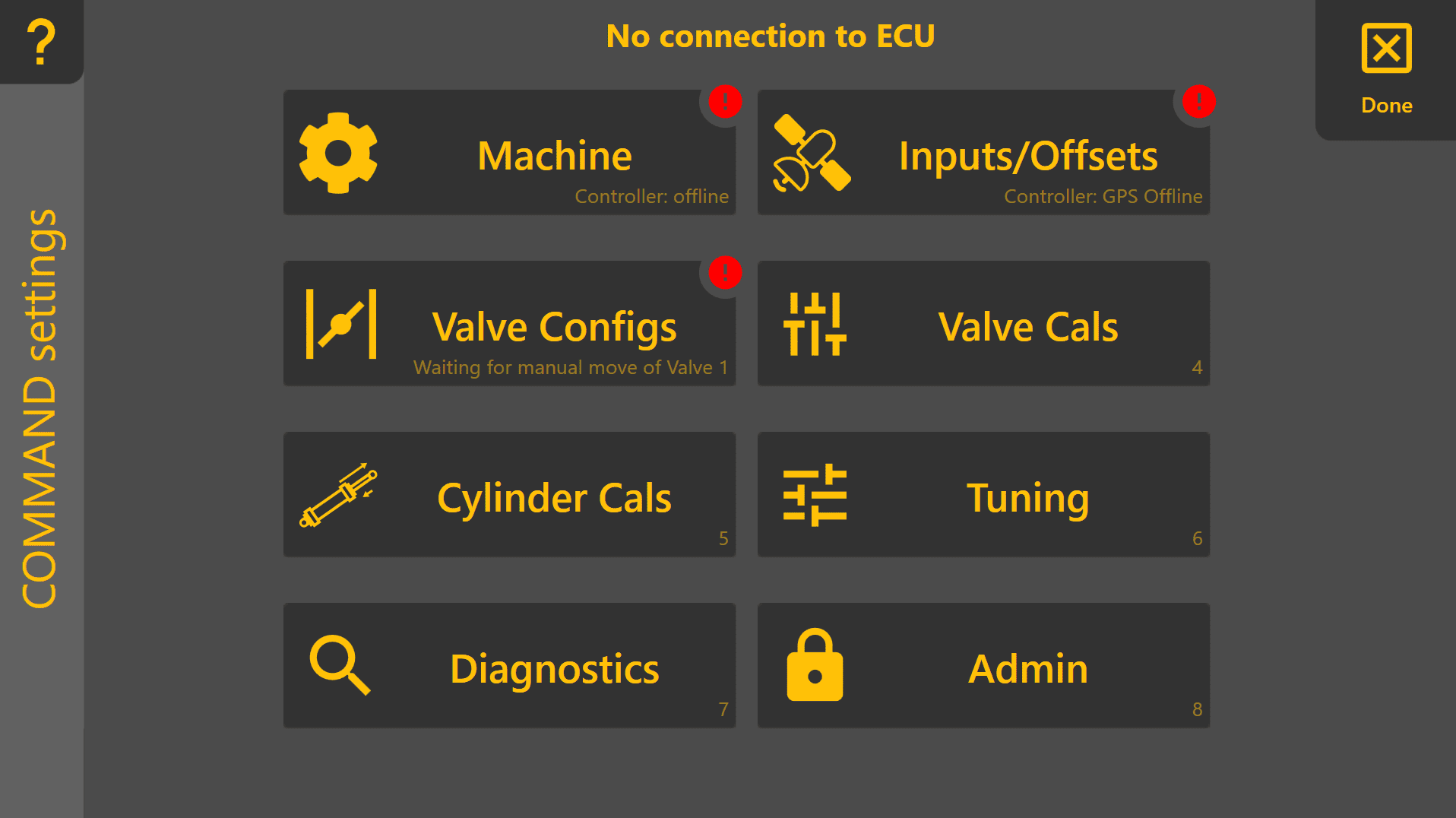
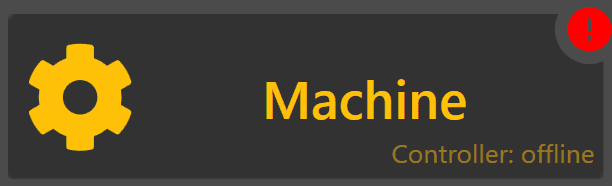
The Machine page is used to setup the connection between Level COMMAND software and the COMMAND ECU in addition to selecting the machine profile being used. To get to this page, first go to the COMMAND Settings page and click the top left 'Machine' button.
ECU Serial Connection
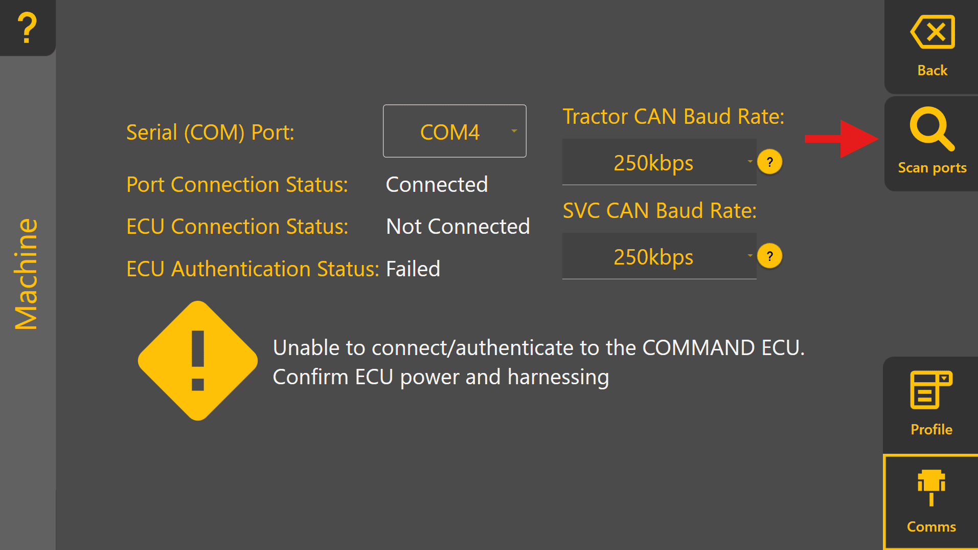
Begin by connecting to the COMMAND ECU using the Comms tab. Select the correct COM port from the list OR
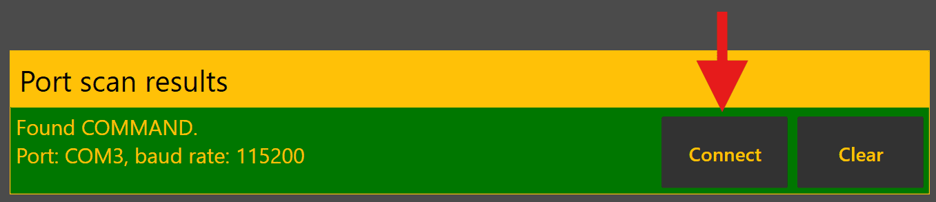
Click the 'Scan ports' button to search for COMMAND data among all serial ports present. If the ECU is detected successfully, click Connect.
Connection Failure
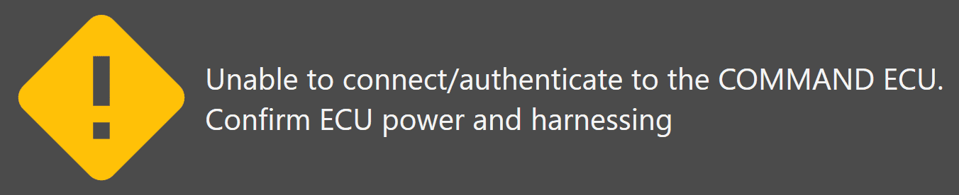
If Level COMMAND fails to connect to the ECU over the chosen COM port, a warning will be displayed. Verify power and communication connections before retrying.
Successful Connection
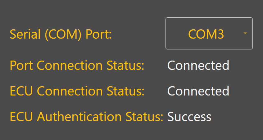
Once connected to the ECU successfully, Level COMMAND will:
- Establish communication with the ECU
- Read stored parameters
- Load the current machine configuration
Once connected, Continue to 3.2 | Selecting A Machine Profile.
3.2 | Checking for Software & Firmware Updates
Before proceeding with machine configuration and calibration, ensure both the Level COMMAND application and the COMMAND ECU are updated to the latest available versions.
Recommended Procedure
- Connect to the COMMAND ECU successfully as performed in section 3.1.
 Press Back to return to the COMMAND Settings Overview page, then press Done to return to the Apply View.
- Check for available Level COMMAND software updates by pressing More > Update/Changelog > Download Updates:
- Allow the updates to complete and restart Level COMMAND if prompted.
- Return to the Apply View.
- Check for available COMMAND ECU firmware updates by pressing More > COMMAND Settings > Admin > Update to Latest.
- Allow any updates to install completely.
- Restart the ECU by turning off the machine and restarting.

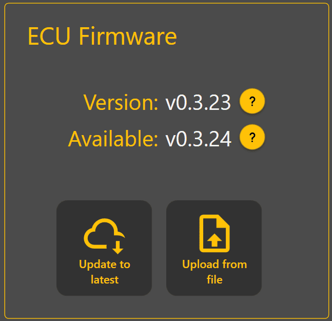 Software and firmware updates may include:
- Feature improvements
- Bug fixes
- GNSS compatibility updates
- Calibration improvements
- Stability enhancements
After updating:
- Verify communication with the ECU
- Ensure no active faults or warnings are present at machine-level.
Continue to 3.3 | Selecting A Machine Profile.
3.3 | Selecting A Machine Profile
Profile
 The profile is used to select the type of implement being used, for detailed information on available profiles please refer to the COMMAND hardware manual section.
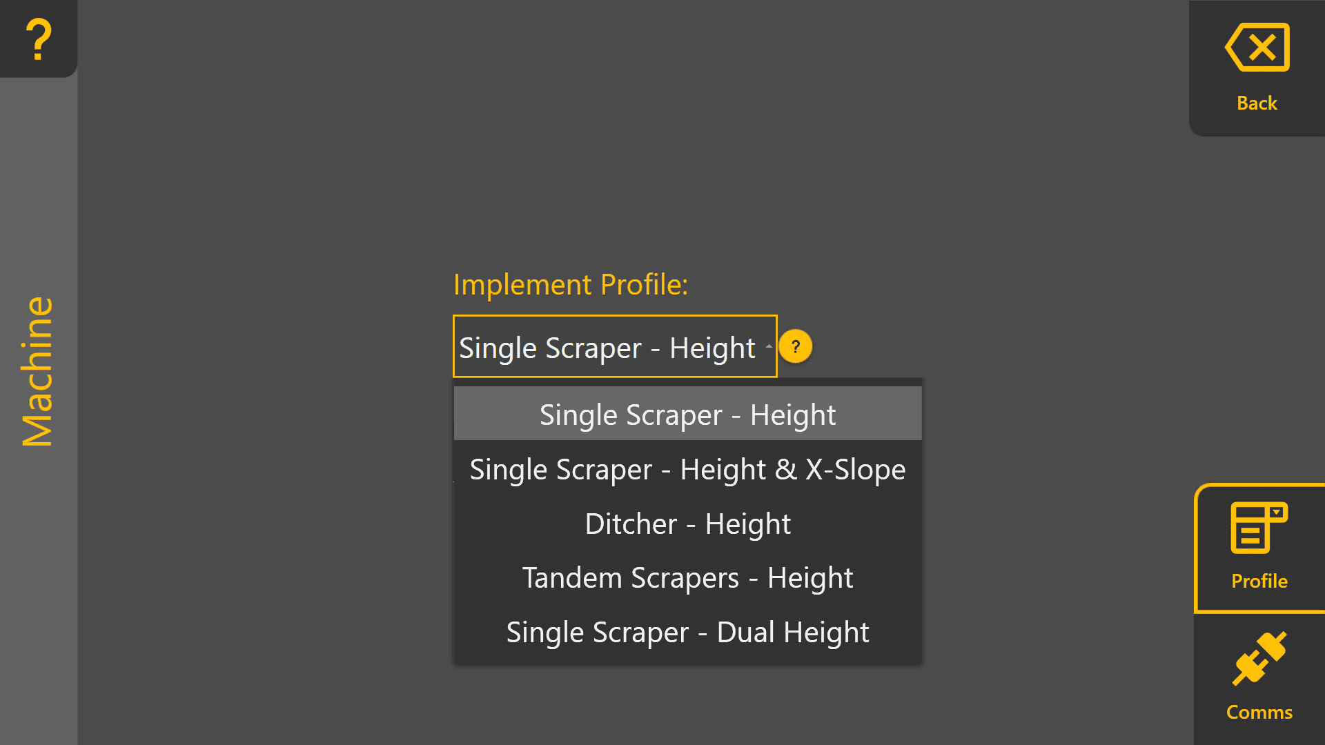
After selecting the appropriate machine profile, enter a Blade Width in the field shown - a red exclamation mark icon indicates that the blade width has not been set yet.
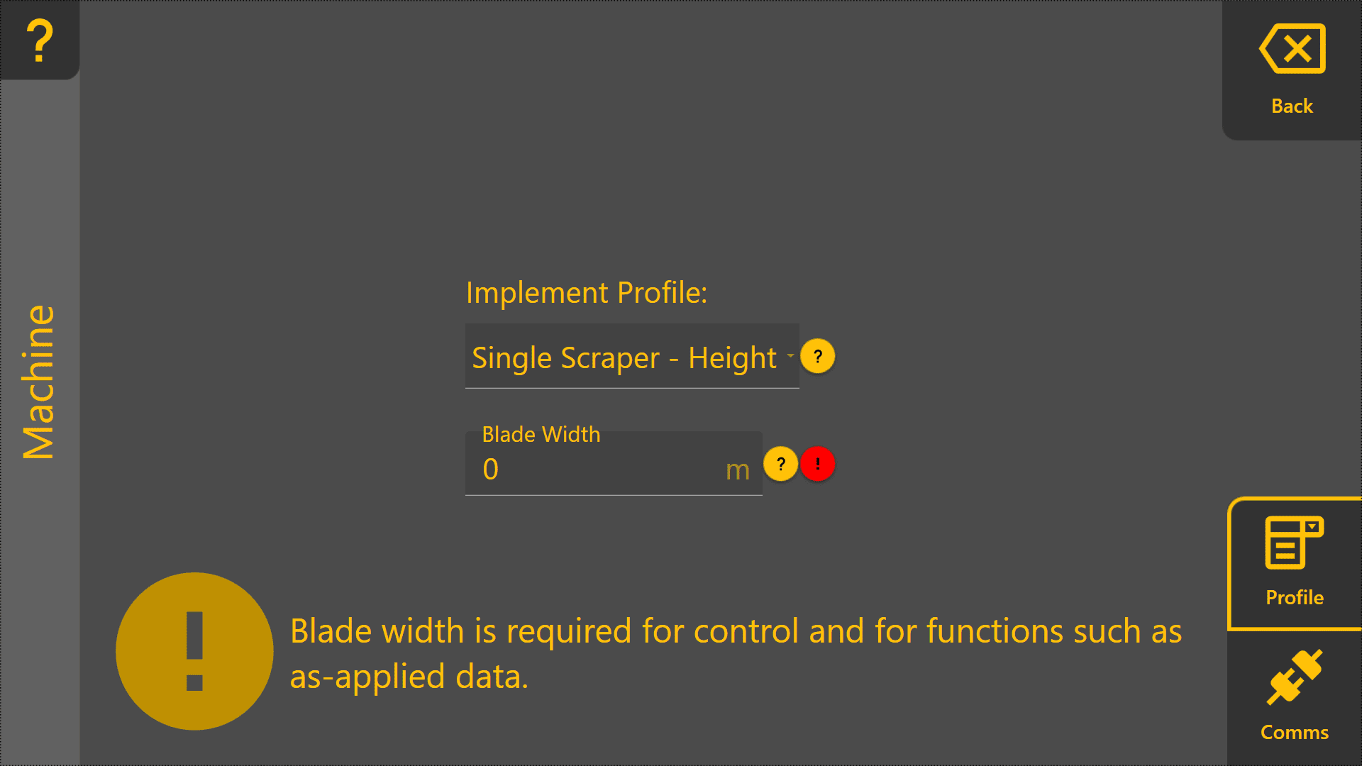
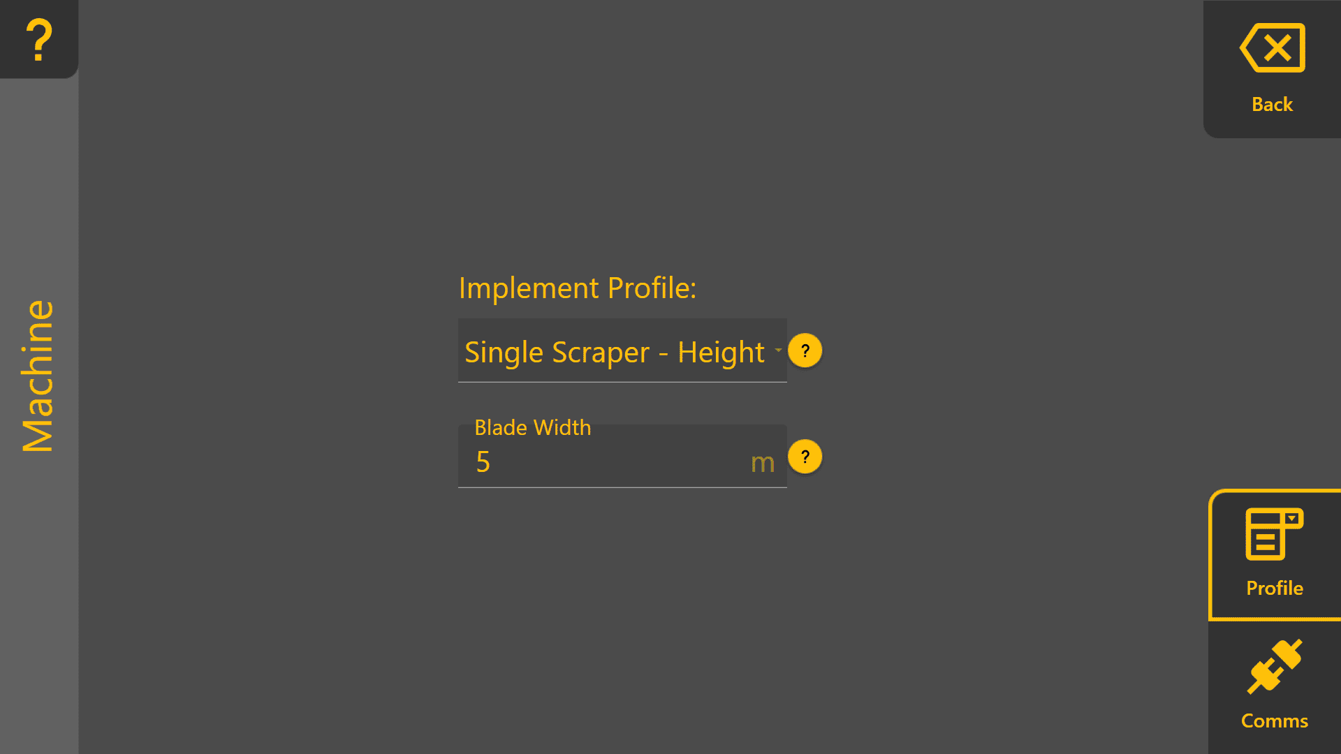
Press "Back" to return to the COMMAND Settings Overview and continue to 3.4 | Configuring GNSS.
3.4 | Configuring GNSS
The Inputs/Offsets page is used for selection of input sensors, such as GNSS receivers for height control or Inertial Measurement Units (IMU) for terrain compensation and Tilt / X-slope control.
GNSS Input Configuration
Pre-configuration
Before configuring Level COMMAND for use with receivers such as StarFire, ensure that the following settings have been checked and enabled/disabled as follows within the relevant system (e.g. Greenstar display for StarFire receivers):
Shared Signal - OFF/Disabled
This setting should be set to OFF/Disabled for usage with Level COMMAND.
RTK-X - OFF/Disabled
John Deere RTK-X is a backup correction feature for StarFire™ receivers that maintains high-accuracy guidance for up to 14 days if the primary radio or mobile RTK signal is lost.
This setting should be set to OFF/Disabled for usage with Level COMMAND.
 Inputs
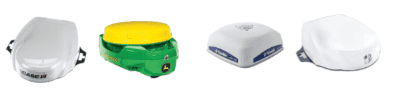
All COMMAND machine profiles have at least one height control function intended for use with a GNSS receiver for vertical position feedback.
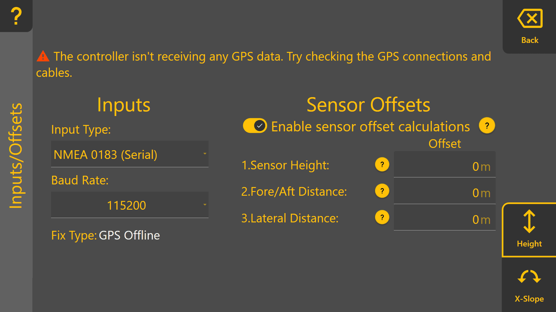
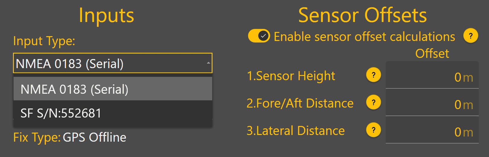
Tap on the dropdown box below Input Type to view the different GNSS input options currently available.
This dropdown will update with any StarFire or NMEA 2000 receivers currently connected, which are then displayed with either "SF" or "N2K" followed by the receiver serial number.
Verify that each function ("Height" if using a single receiver, "Height 1" & "Height 2" if using tandem or dual receivers) has a Fix Type of RTK before proceeding.
Fix Type MUST be RTK for accurate automatic control operation - lower accuracy fix types such as GPS only, Differential or Float RTK are not appropriate for accurate implement position control. Poor GNSS quality will affect machine positioning and automatic control performance.
StarFire Example:
NMEA 2000 Example:
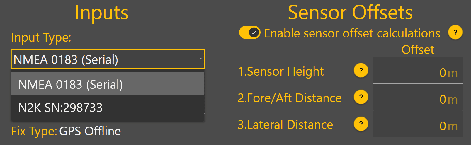
Once the GNSS receiver has been selected, Fix Type should change from GPS Offline to another status to indicate the current GPS quality. If GPS Offline is still shown, the receiver may still be initialising.
Sensor Offsets
If using a GNSS receiver with Level COMMAND that is not capable of IMU-based terrain compensation, sensor offset calculations can be enabled.
Blade Width - Enter the height of the GNSS receiver's measurement point above the cutting edge of the blade.
Positive = Above the cutting edge
Negative = Below the cutting edge
Fore/Aft Distance - Enter the distance forward or backward from the cutting edge of the blade to the GNSS receiver centre point.
Positive = Behind the cutting edge
Negative = In front of the cutting edge
Lateral Distance Enter the distance between the GNSS receiver centre point to the middle of the cutting edge of the blade.
Positive = To the right side of the middle as if standing behind the scraper
Negative = To the left side of the middle as if standing behind the scraper
Sensor Offsets Example:
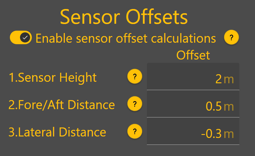 In the example screenshot below, the GNSS receiver has been mounted:
- 2 metres above the blade cutting edge
- 0.5 metres behind the blade (away from the tractor)
- 0.3 metres to the left of the middle of the blade (looking toward the rear of the scraper)
Inputs / Offsets setup is now complete for profiles with only a height control function.
If using Height & X-Slope, Tandem receiver or dual receiver profiles, continue on to set up the second control function's inputs/offsets.
Verifying GNSS Status & Health
GPS Thresholds
GPS Thresholds define the minimum GNSS performance requirements expected by Level COMMAND. These thresholds are used to determine when GNSS warnings should be generated and whether GNSS data quality is suitable for accurate automatic control.
The default values supplied by T3RRA have been selected to provide reliable operation in most environments and should not normally require adjustment. Only modify these values if directed by T3RRA Support or if site-specific conditions require alternative settings.
To access GPS Thresholds:
- Return to the main Level COMMAND screen.
- Press More on the right-hand side of the display.
- Select GPS Thresholds.
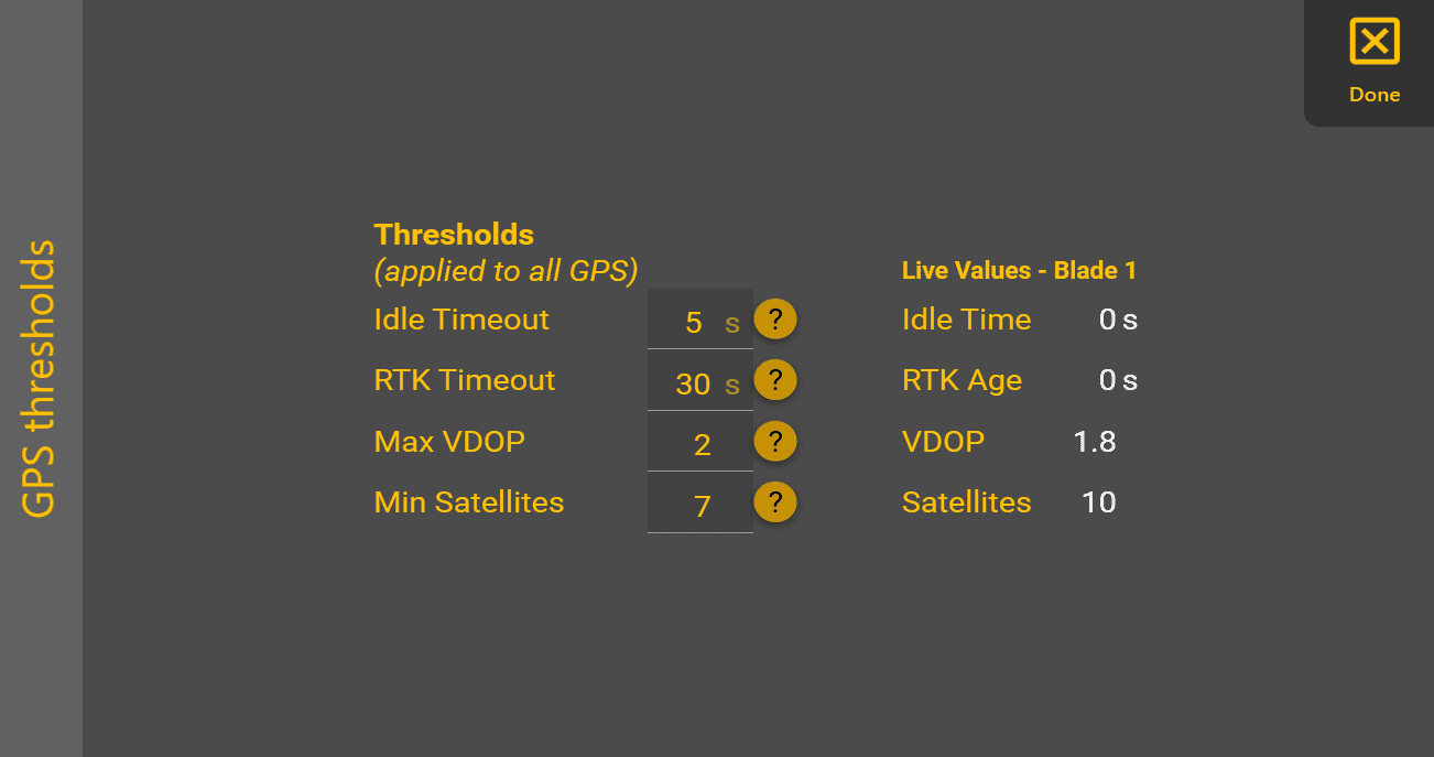
The GPS Thresholds screen allows the following values to be configured:
Idle Timeout
The maximum allowable period of time that GNSS data can stop being received before a warning is generated.
RTK Timeout
The maximum acceptable age of RTK correction data. If corrections exceed this age, GNSS accuracy may no longer be suitable for automatic control.
Max VDOP
The maximum allowable Vertical Dilution of Precision (VDOP).
Lower VDOP values generally indicate better vertical positioning accuracy. A value below 2 is recommended for normal operation.
Min Satellites
The minimum number of satellites required before a warning is generated.
Note that some receivers only report a maximum of 12 satellites even when additional satellites from multiple constellations are being used. This behaviour can be normal and depends on the receiver manufacturer.
Live Values
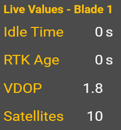
The Live Values panel displays the current GNSS values being compared against the configured thresholds.
During commissioning, verify that:
- GNSS data is updating continuously.
- RTK correction age remains within limits.
- VDOP remains within the configured threshold.
- Satellite count satisfies the minimum requirement.
The Live Values panel provides a convenient method of confirming GNSS health during commissioning. For continuous monitoring during operation, GNSS information can also be displayed using the Widget Interface.
Once GNSS receiver selection, sensor offsets and GPS Threshold verification have been completed, GNSS configuration is complete.
To get back to COMMAND Inputs set up, return to the Level COMMAND main page and press "More" at the right side of the screen > COMMAND Settings > Inputs/Offsets.
To set up a secondary receiver for Height 2, i.e. Tandem implements or implements with dual receiver follow the process above for Height 2 as well.
X-Slope Input Configuration
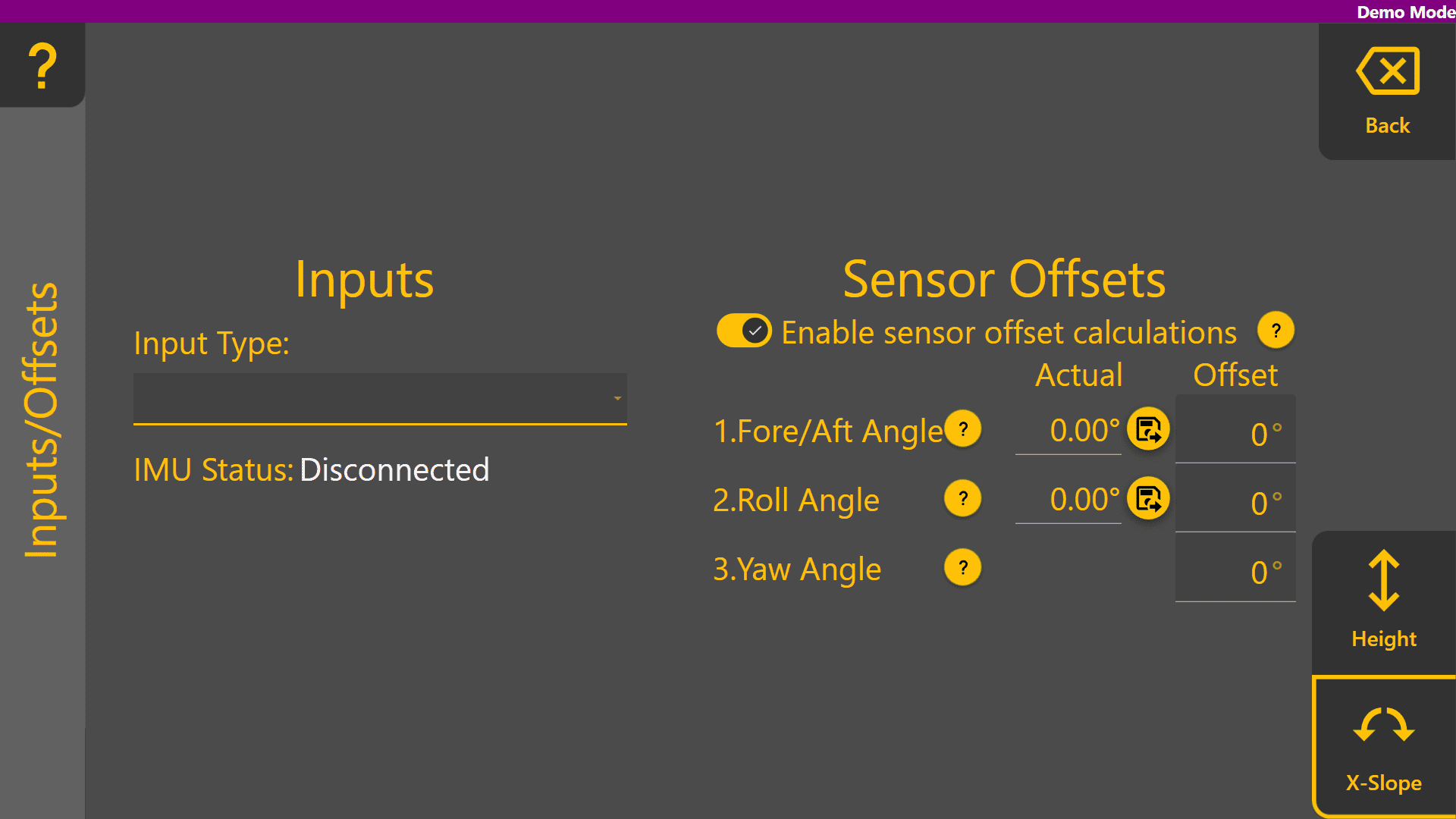
Some COMMAND machine profiles have a Tilt / X-slope control function intended for use with an IMU for blade tilt / x-slope angle feedback. Tap on the Input Type dropdown box to view currently connected IMU sensors, and select the desired input sensor.
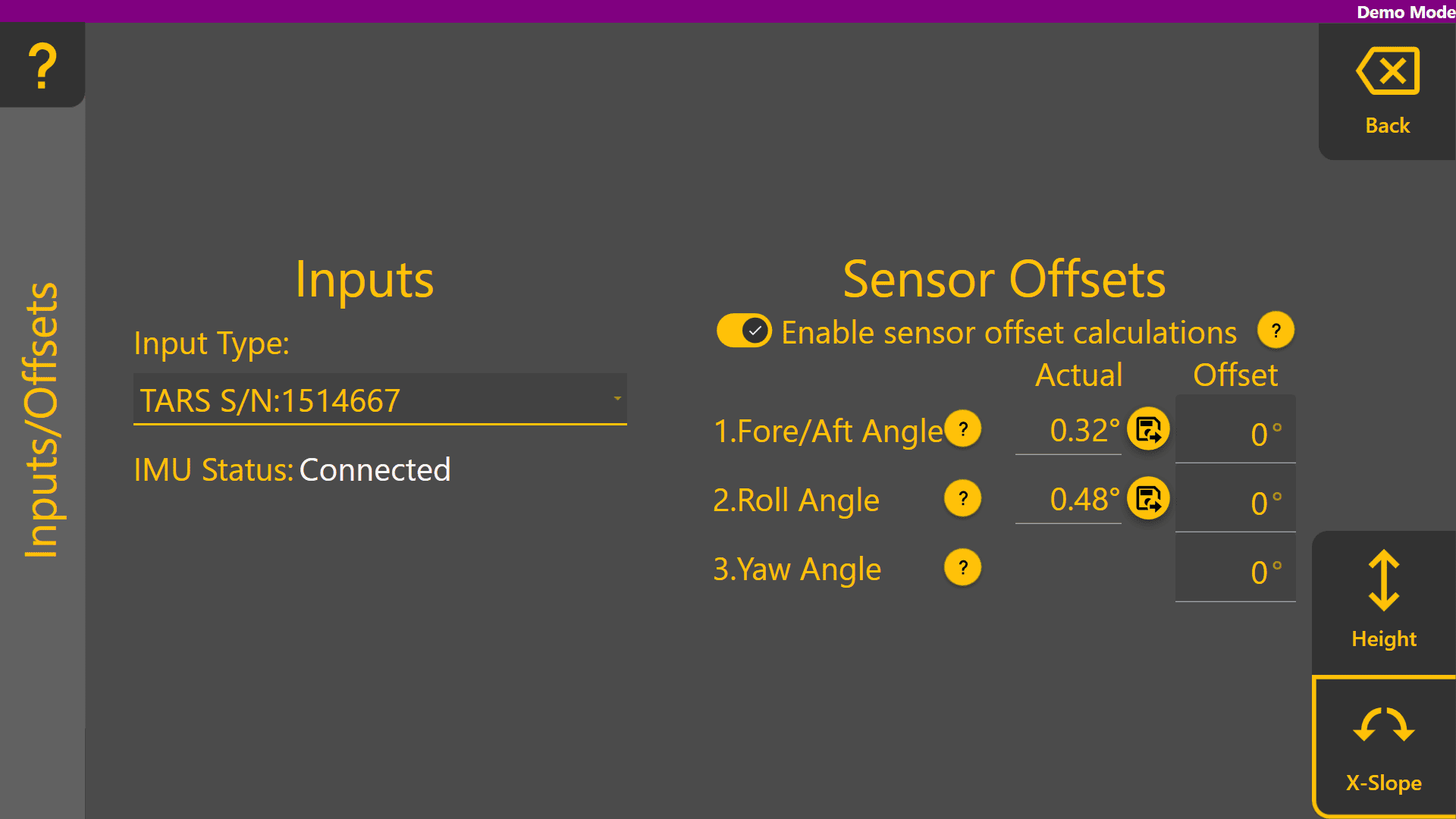
Once selected, IMU Status will change to Connected. Additionally, the Actual values for Fore/Aft Angle and Roll Angle below Sensor Offsets will begin updating with the current angle of the selected IMU sensor.
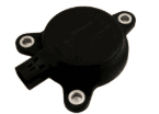
Accounting for IMU Mounting with Offsets
 In cases where the IMU sensor has not been mounted on the blade at a perfect 0 degree pitch and/or roll angle, the save offset buttons can be used to set the Fore/Aft Angle and Roll Angle offsets to the current angle reading. Before doing so, use equipment such as a spirit level, or a known level surface to ensure the blade is completely level. Once done, press the Save icons to set each of the two offset values to the current angles.
Offsets are saved in the COMMAND ECU and only need to be changed if the position of the IMU sensor has changed, or if fitting the IMU to a different implement.
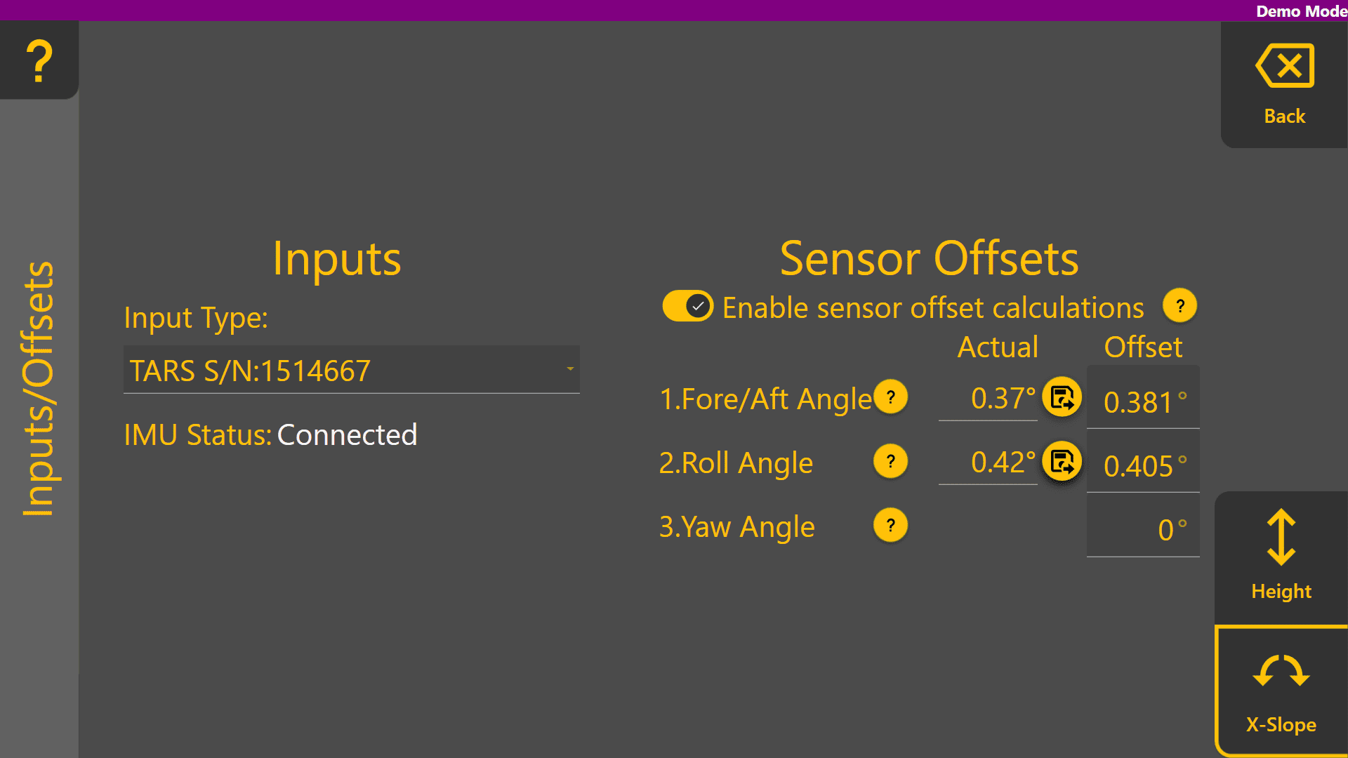
Press "Back" to return to the COMMAND Settings Overview and continue on to 3.5 | Setting Valve Configurations.
3.5 | Configuring Valve Outputs
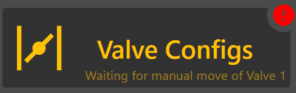
The Valve Configs page is used to set up the control output interface for each control function. Appropriate signals of that interface type are then generated when automatic or manually controlling the implement. External joystick inputs are also configured on this page when making use of an analog or J1939 CANBUS joystick.
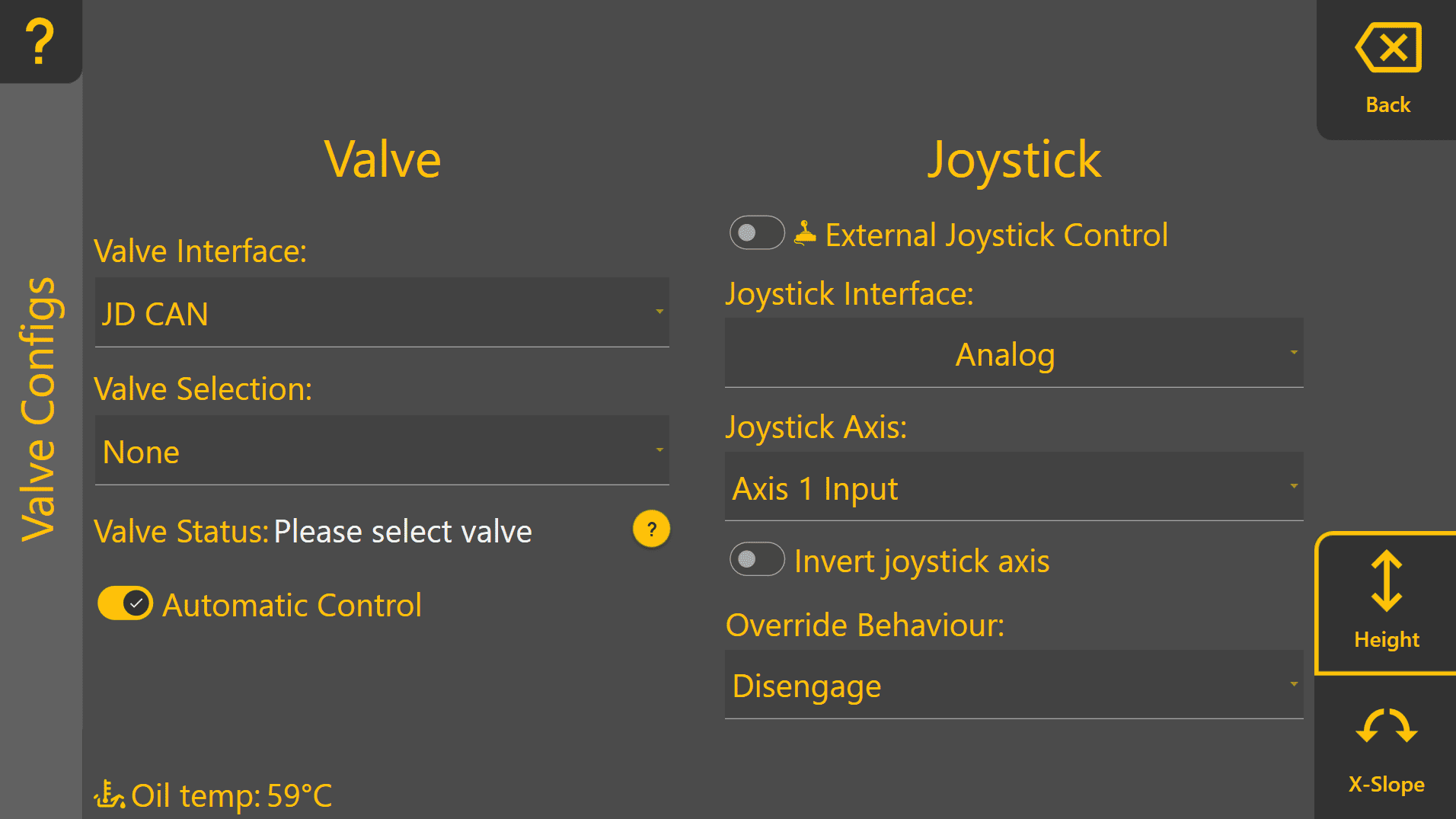
At the bottom right corner of the screen, buttons will be shown if there are two available control functions. If using a Height control only machine profile, only the Height page is displayed.
Selecting the Valve Interface
Select the appropriate Valve Interface for the tractor, machine or external valves being used for that function. To begin with, set the desired Valve Interface type for the Height control function.
Different Valve Interface selections display different Valve Number selections depending on how they work - for more information please see the section in the COMMAND manual.
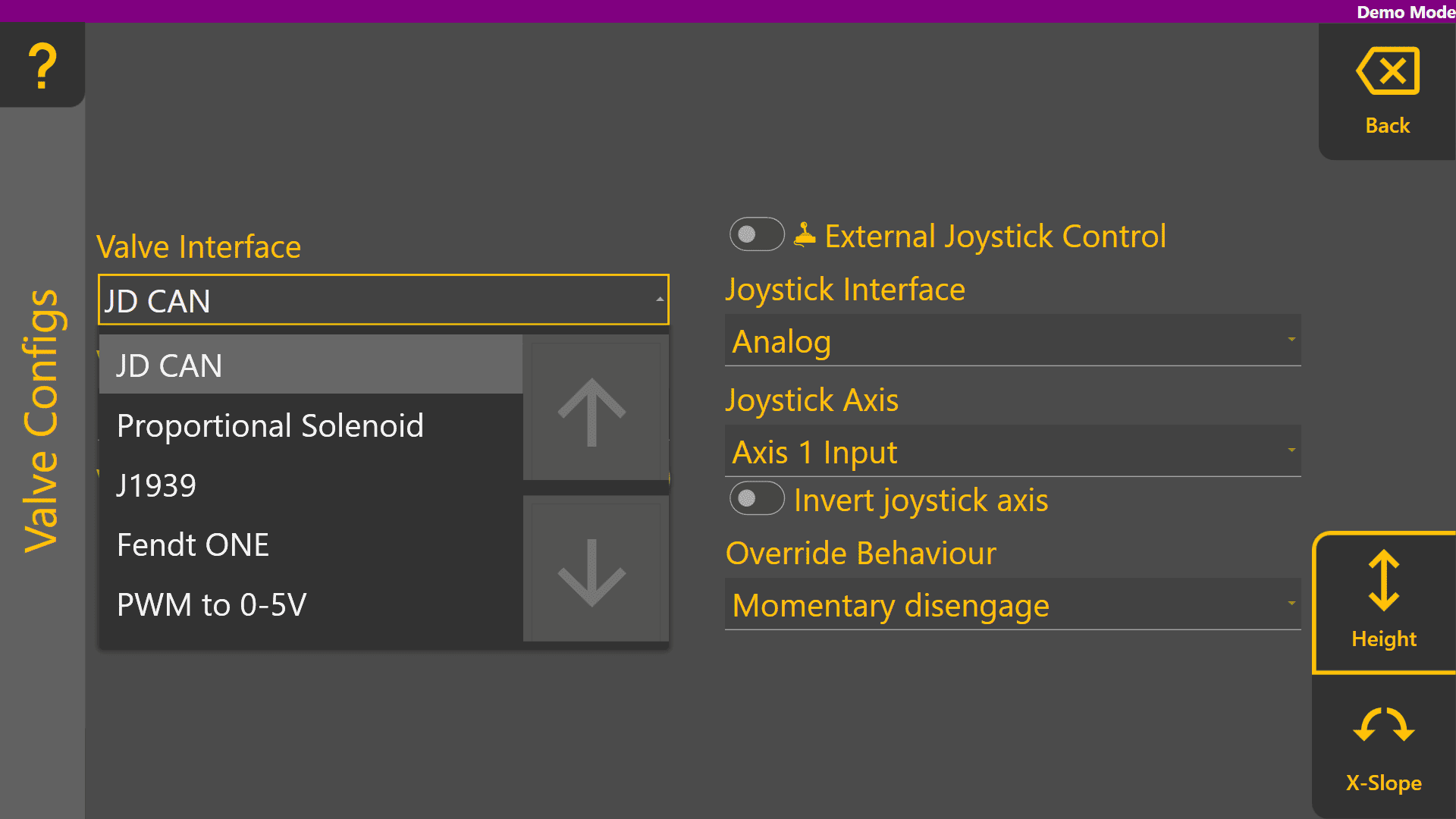
Selecting the Valve Number
When selecting Valve Interface options like JD CAN, J1939 and Fendt ONE will only display valve numbers that have been detected on the ISOBUS or machine CANBUS. Below shows an example of the dropdown with the tractor switched off.
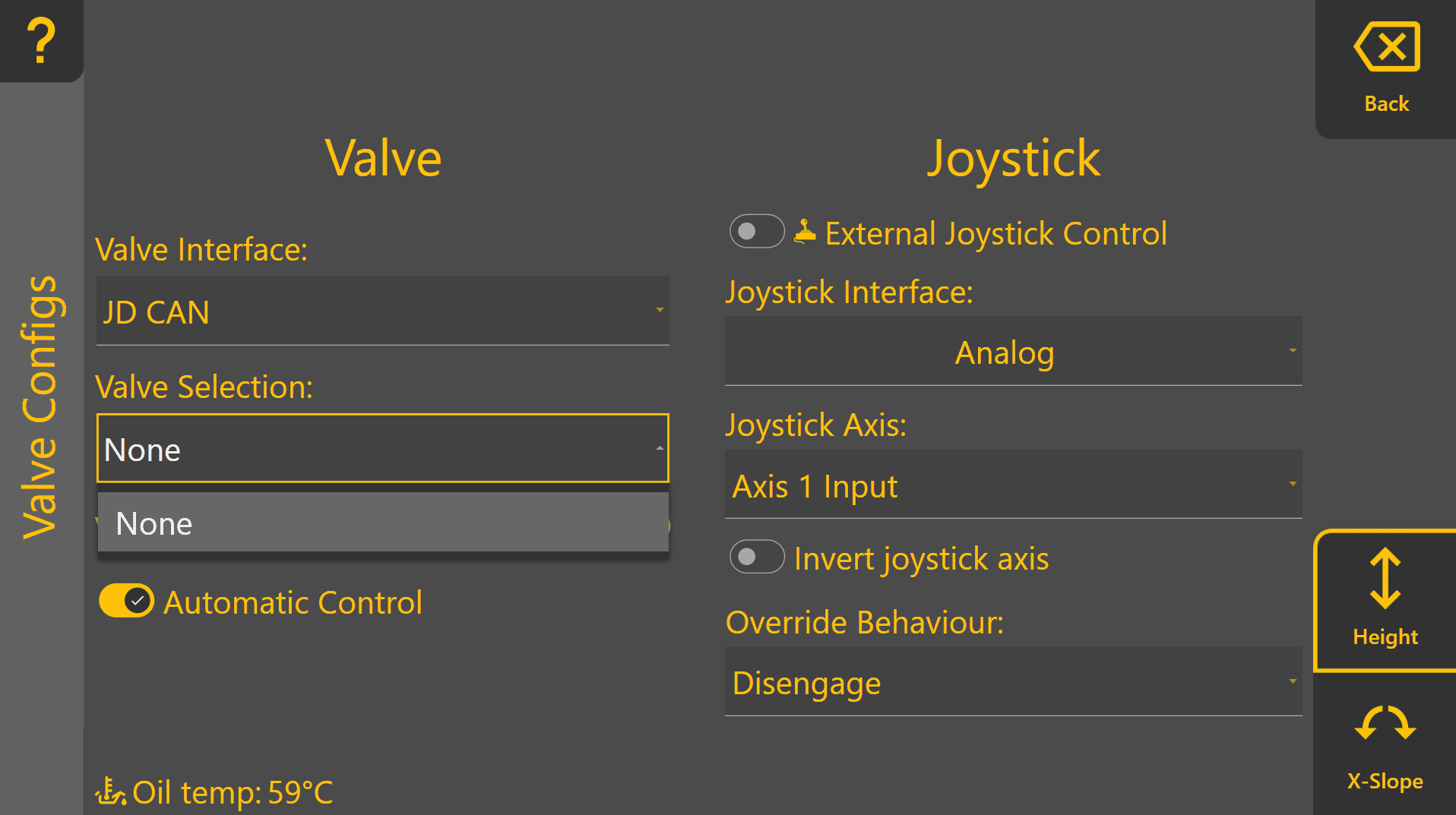
Once detected on the ISOBUS or machine CANBUS, any available SCV / Remote / Auxiliary valve selections will be displayed in the Valve Selection list as shown:

Analog valve interfaces such as Proportional Solenoid and PWM to 0-5V always display all available Valve Selection options. Valve signals for these selections generally rely on harnessing to connect the outputs of the COMMAND ECU to the proportional solenoid or laser system inputs.
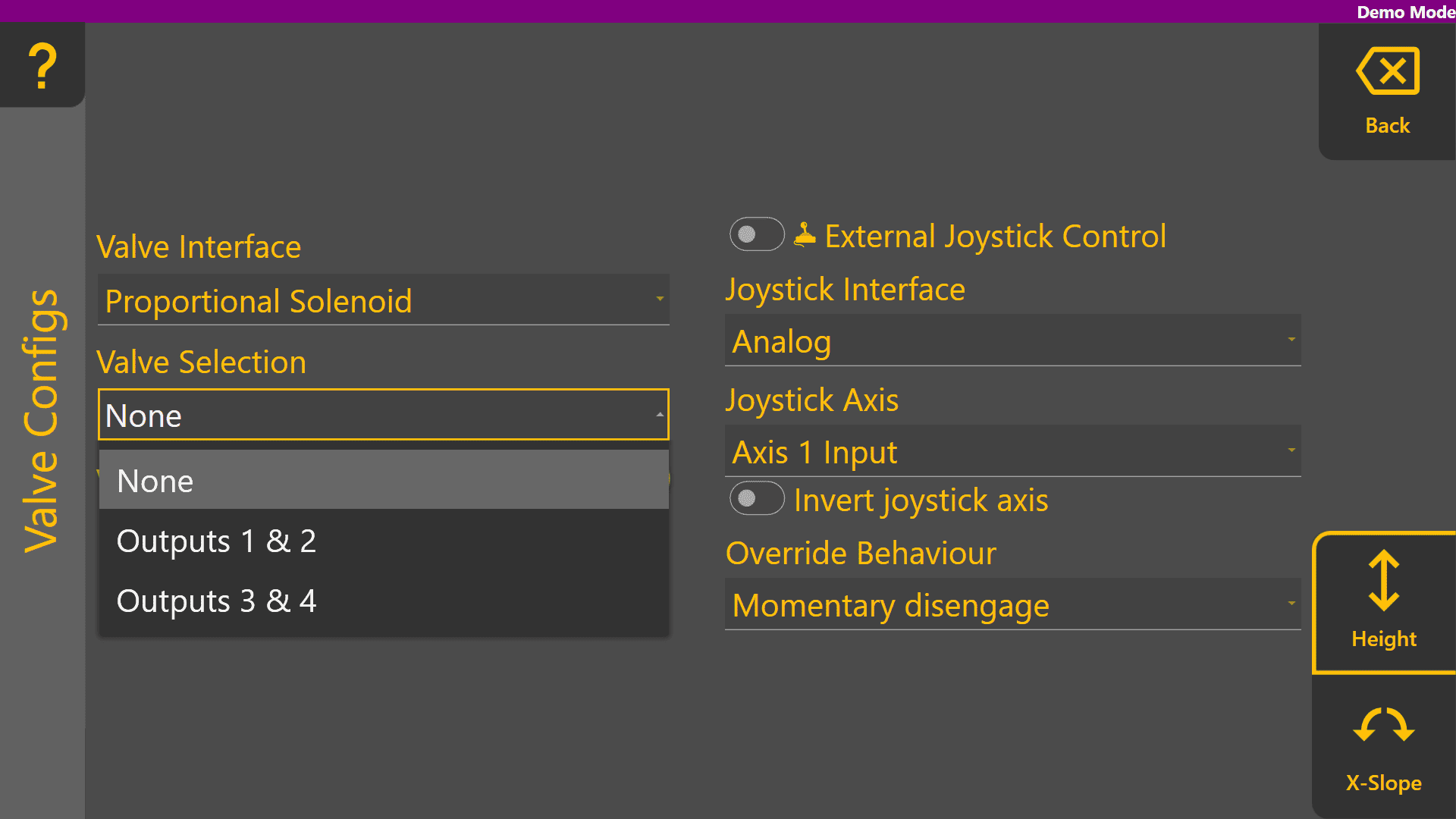
Valve Status
Valve Status provides information on the current status of the selected Valve Interface and Valve Selection. The table below explains each of the different possible valve statuses that may appear:
| Status | Description |
| Valve Unavailable |
The selected valve is not available for use.
|
| Waiting for Manual SCV Input |
Move the SCV lever corresponding to the selected SCV - this must be done when using John Deere tractors.
|
| Short to Ground |
An overload has been detected and the resistance between the valve signal output pin and ground is near-zero, holding the output low.
|
| Short to Batt |
An overload has been detected and the valve signal output pin is being fed power from another source holding the output high.
|
| Open Load |
A connection or valve issue has been detected, and the resistance between valve signal output pin is too high, indicating a broken wire or valve solenoid/coil.
|
| SCVs Locked |
The SCVs must be unlocked using the console SCV padlock button.
|
| System Not Armed |
The COMMAND Arm/Engage switch must be armed or re-armed.
If the Arm/Engage switch is currently Off:
If the Arm/Engage switch is currently in the middle position:
|
| Ready |
The selected valve is currently not active and the ECU is ready for automatic control or manual control commands for that function.
|
External Joystick Setup

Selecting the Joystick Interface
Select the appropriate Joystick Interface for the Height function, depending on the joystick being used:
- If using an analog voltage based joystick, select "Analog"
- If using a J1939 CANBUS based joystick, select "J1939"
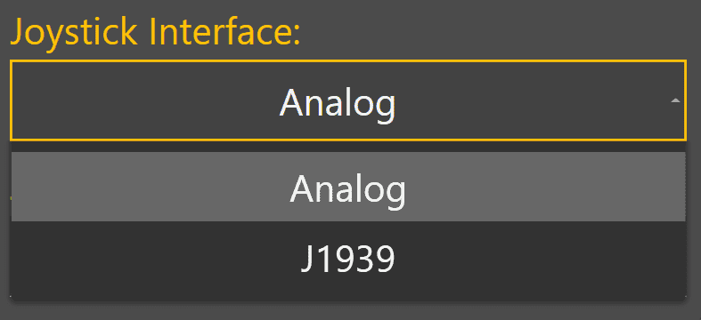
Selecting the Joystick Axis (Analog)
Next, select the appropriate Joystick Axis. For the Analog interface, Axis 1 is intended for the joystick Y-axis, Axis 2 is intended for the joystick X-axis and Axis 3 is intended for the joystick Z-axis if present.
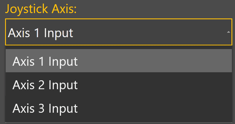
Selecting the Joystick Interface (J1939 / CAN)
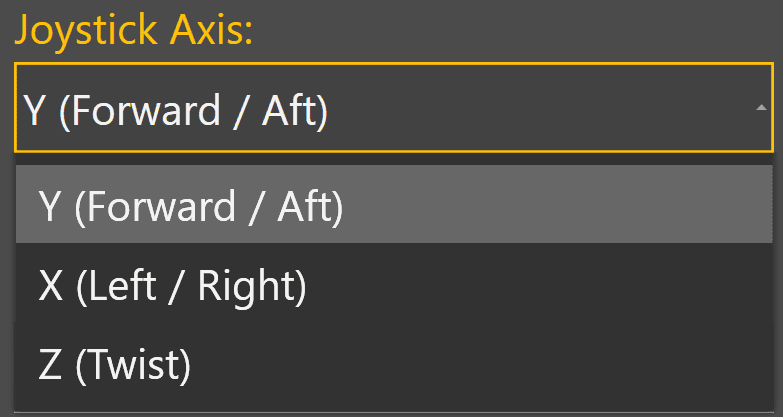
For the J1939 interface, select the joystick axis to be used for the function, e.g. Y-axis for manual height control.
Swapping the Joystick Axis' Control Direction
 If moving the joystick in a certain direction causes the wrong physical movement direction, the axis can be inverted using the Invert Joystick Axis toggle.
Selecting the Override Behaviour
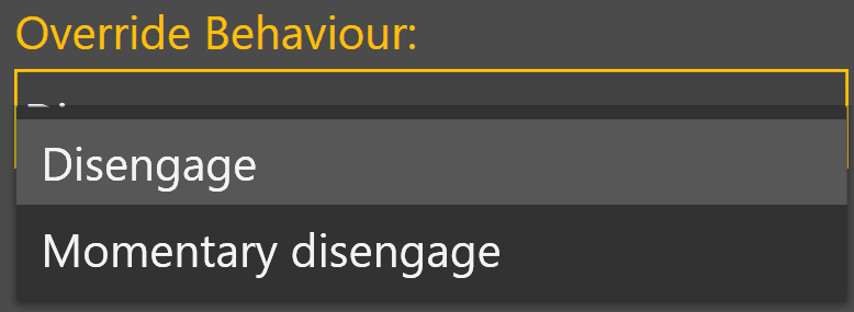 Lastly, select the desired Override Behaviour for the function:
- "Disengage" will cause any joystick movement to disengage automatic control mode, requiring the operator to press the engage button again to resume automatic control.
- "Momentary Disengage" will cause any joystick movement to only momentarily disengage automatic control mode. Once the joystick is no longer being moved, COMMAND will resume controlling the implement automatically.
Regardless of Override Behaviour selection, COMMAND will always prioritise joystick/manual control signals over automatic control signals to maintain full operator control of the implement.
Example Height Valve Configuration Page
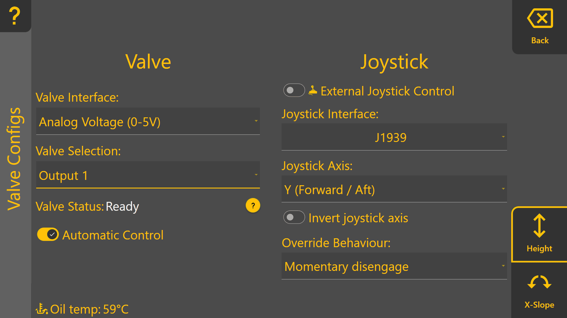
Below shows an example of a configuration using PWM to 0-5V Valve Interface, using the T3H-V001 valve adapter on Output 1, with Automatic Control enabled. External Joystick Control has also been enabled for use with a J1939 CANBUS joystick, with the Y-axis controlling the Height function and will momentarily disengage automatic control when the joystick is moved.
Example X-Slope Valve Configuration Page
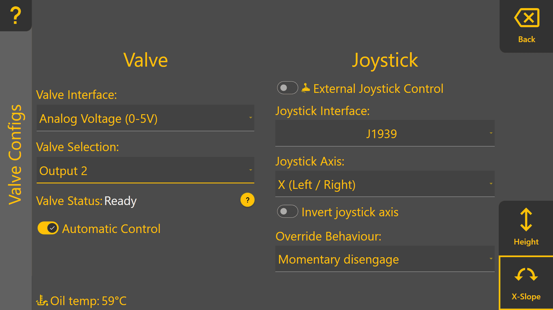
Swapping over to the X-Slope function using the bottom right button, an example configuration shown below is set up to use PWM to 0-5V Valve Interface, using the T3H-V001 adapter on Output 2. X-Slope is enabled for automatic control, and also has External Joystick Control enabled for use with a J1939 CANBUS joystick on the X-axis, momentarily disengaging when the operator moves the joystick.
Press "Back" to return to the COMMAND Settings Overview page and continue on to 3.6 | Valve Threshold Calibration.
3.6 | Valve Threshold Calibration
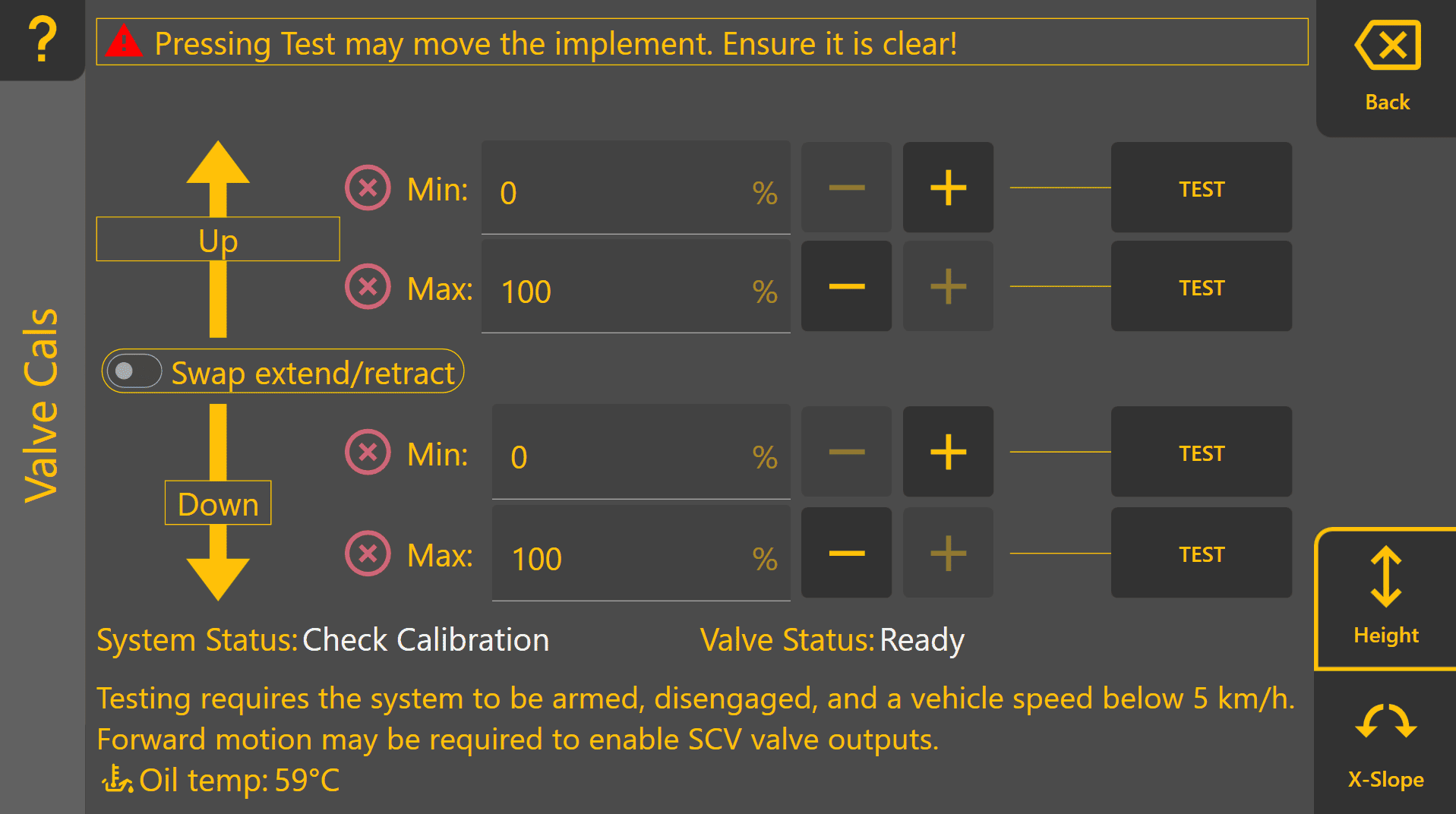
Valve Threshold Calibration establishes the minimum and maximum hydraulic outputs used by Automatic Control. Correct calibration ensures the implement can move smoothly for small corrections while still achieving full operating speed when required.
Access the COMMAND valve calibration page by going to: More > COMMAND Settings > Valve Cals.
- Minimum Threshold (Min %) determines the lowest output that reliably opens the hydraulic valve.
- Maximum Threshold (Max %) limits the highest output available to Automatic Control.
Calibration Procedure
The COMMAND ECU will not request movement of the implement unless the user has pressed one of the test buttons and is holding the engage button.
- Select the function and direction to calibrate.
- Press TEST and hold the machine ENGAGE button when instructed.
- Increase Min. % until the implement begins moving consistently at a very slow speed, e.g. about 1 centimetre per second.
- Adjust Max. % as required:
- For proportional solenoids, limit output to approximately 1800 mA.
- Reduce further if lower maximum implement speed is desired.
- Repeat for all active directions and functions.
Calibration Test Buttons
The "+", "−" and "TEST" buttons are used during the calibration process to incrementally increase or reduce a given threshold, which can then be tested using the process described in the next section.
Calibration Progress Icons
This icon indicates that a value has not been calibrated yet. All minimum and maximum values for all active functions must be calibrated before performing automatic control.
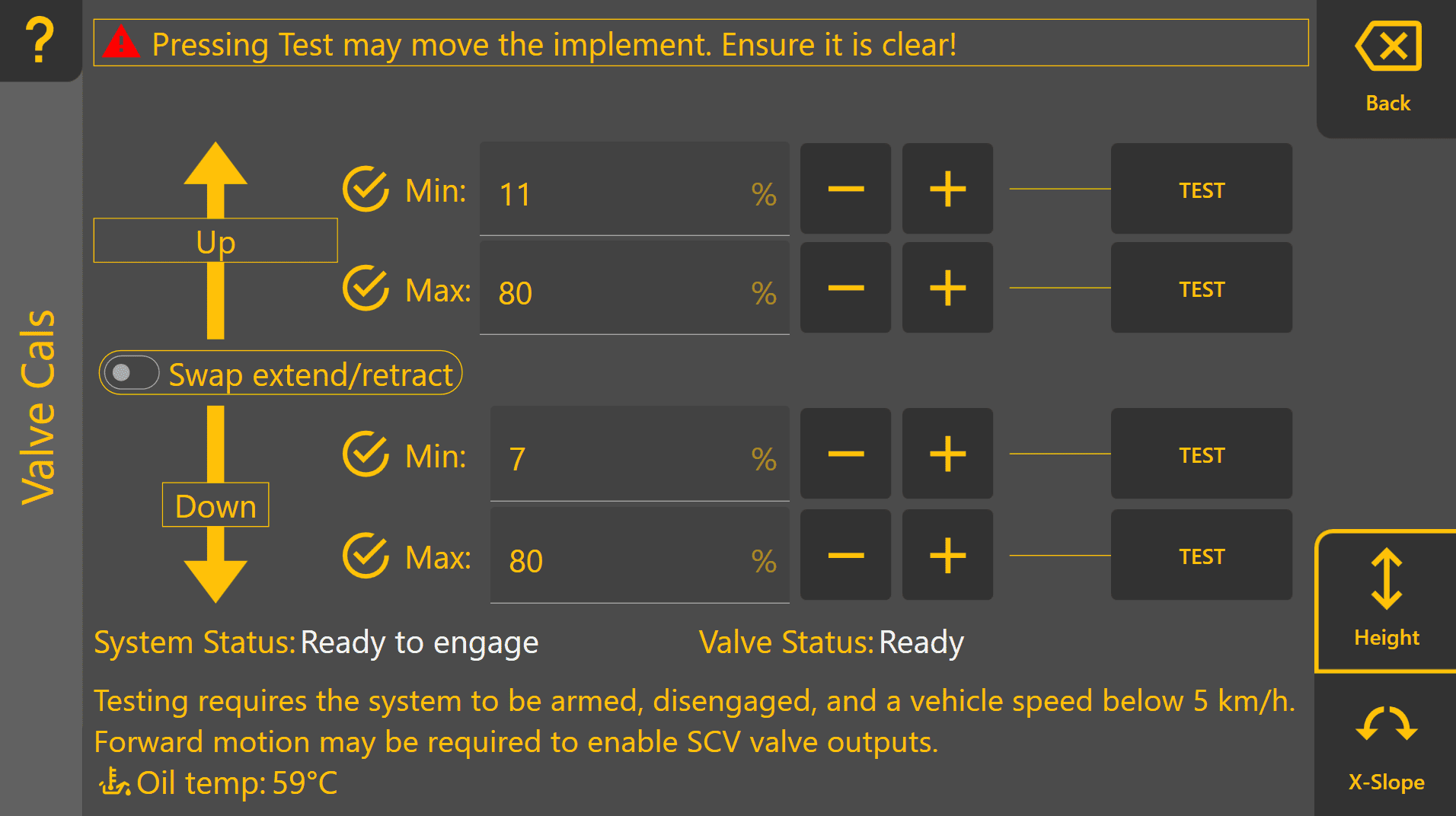
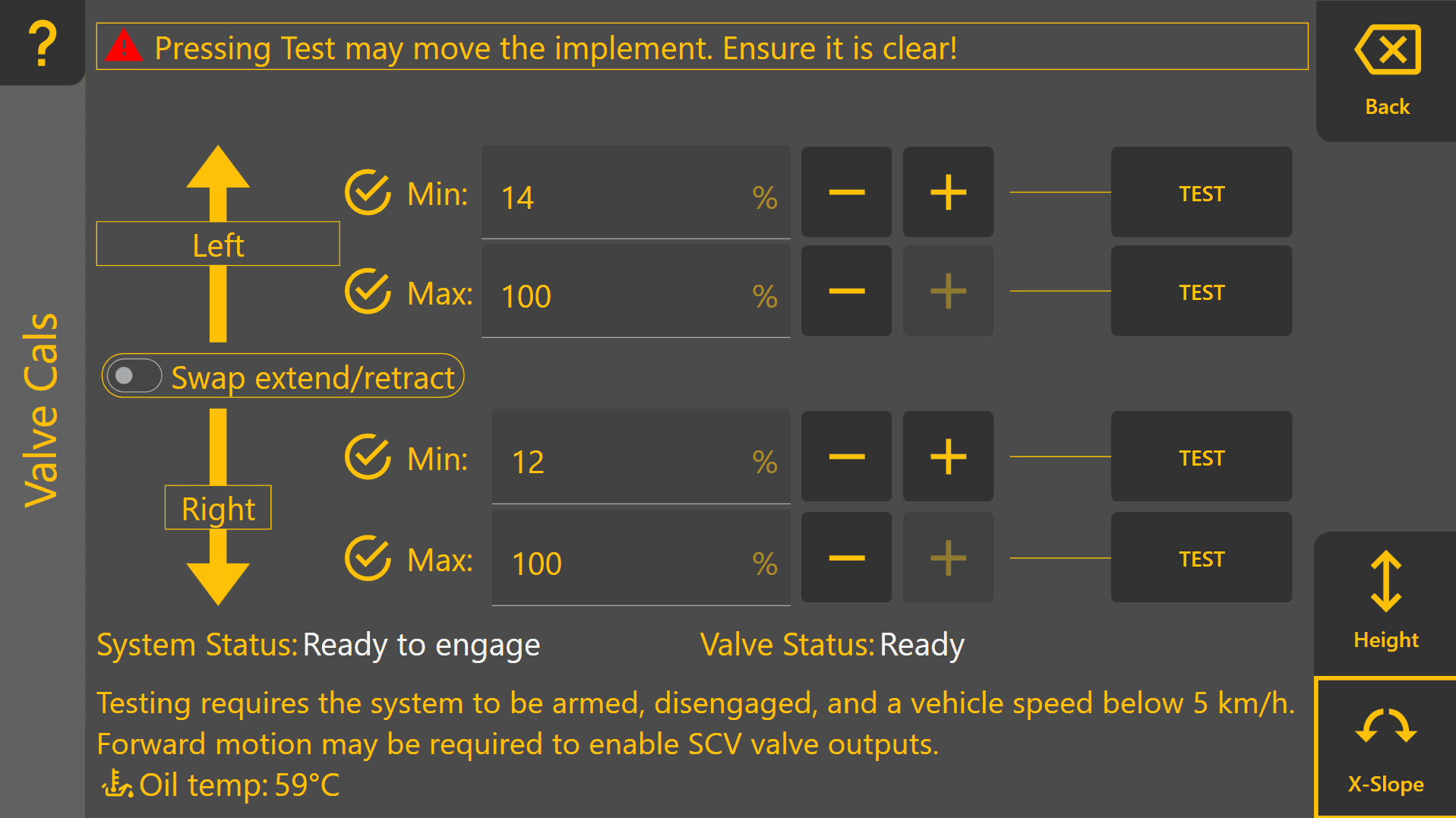
This  icon indicates that a value has been calibrated. Once all min and max values display this icon, the function has been successfully calibrated.
Ticks next to Min or Max values mean that the test button was pressed, but do not indicate a correctly calibrated function.
Example for Completed Height Function
Example for Completed X-Slope Function
Verification
Verify that:
- Implement movement begins smoothly when Min % is tested.
- No excessive delay or valve chatter occurs.
- Full-speed movement is available when Max % is tested without hydraulic instability.
- All calibration indicators show as complete before commissioning proceeds.
Continue on to 3.7 | Cylinder Ratio Calibration.
3.7 | Cylinder Ratio Calibration
Overview
 Cylinder Ratio Calibration compensates for differences in implement movement speeds between opposing control directions. Hydraulic systems rarely move at identical speeds in both directions. Differences in cylinder geometry, implement weight, hydraulic flow characteristics, machine design and gravity can all influence the speed at which the implement moves.
For elevation control, the implement may raise more slowly than it lowers due to implement weight and hydraulic loading.
For cross-slope control, left and right tilt movements may also occur at slightly different rates due to cylinder geometry and hydraulic system characteristics.
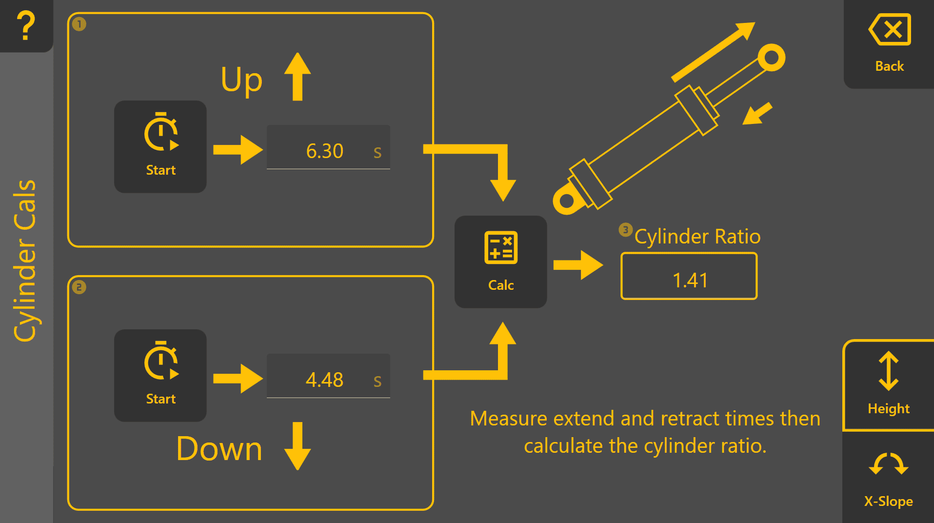
Cylinder Ratio Calibration measures the time taken to move the implement through its full range of motion in each direction and automatically calculates a correction ratio used by Automatic Control.
Calibration Procedure
Elevation (Raise / Lower)
-
Position the implement at its lowest operating position.
- Press Start in the Up section.
- Immediately raise the implement at full manual control speed until maximum height is reached.
- Press Stop when maximum height is reached.
- Press Start in the Down section.

- Immediately lower the implement at full manual control speed until minimum height is reached - do not make contact with the ground, stop the implement before it does.
- Press Stop when minimum height is reached.
- Press Calc to generate the Elevation Cylinder Ratio.
Cross-Slope (Left / Right)
- Position the implement at one end of its available tilt range.
- Press Start Left or Start Right as appropriate.
- Immediately move the implement at full manual control speed until the opposite end of travel is reached.
- Press Stop when the limit of travel is reached.
- Repeat for the opposite direction.
- Press Calc to generate the Cross-Slope Cylinder Ratio.

Verification
After calibration:
- Implement movements should respond consistently in both directions during Automatic Control.
- Neither direction should appear noticeably slower or more aggressive than the opposite direction.
- If hydraulic components, cylinders, valves or plumbing are modified, cylinder calibration should be repeated.
Continue to 3.8 | Tuning Automatic Implement Control.
3.8 | Tuning Automatic Implement Control
The purpose of tuning is to achieve stable, accurate Automatic Control that follows the design surface smoothly without excessive lag or oscillation. The Tuning page provides the controls and feedback required to optimise control performance. To find the tuning page from the Apply View, press More > COMMAND Settings > Tuning.
Tracking and Acquisition Behaviour
Once Automatic Control is engaged, the COMMAND ECU adjusts its control strategy according to the current error between the implement and the design surface.
Automatic Control transitions between Acquisition, Tracking and Out-of-Range regions according to the current error between the implement and the design surface.
The default Tracking Threshold and Acquire Threshold values are suitable for almost all applications and should not normally require adjustment. Modification of these parameters is generally not recommended.
Three operating regions are used:
Tracking Region (e.g. < 10cm Error)
The Tracking Region is the area immediately surrounding the design surface. This region provides the highest grading accuracy and is where the implement should spend most of its operating time.
When the current error is within the configured Tracking Threshold, COMMAND continuously adjusts hydraulic output using its tracking control algorithm to accurately maintain the implement on grade.
By default, the tracking threshold is 10cm for height functions, and 10 degrees for x-slope functions. Within the Tracking Region, hydraulic output is continuously adjusted between the calibrated minimum and maximum valve thresholds according to the current control error.
Acquisition Region (e.g. > 10cm but < 1m Error)
The Acquisition Region exists between the Tracking Threshold and Acquire Threshold.
When the implement is outside the Tracking Region but remains within the Acquire Threshold, COMMAND prioritises returning the implement to the Tracking Region as quickly as possible.
During acquisition, the ECU commands hydraulic output at the calibrated Max % threshold until the implement re-enters the Tracking Region. Once inside the Tracking Region, control automatically transitions back to normal tracking.
Out of Range (e.g. > 1m Error)
If the current error exceeds the configured Acquire Threshold, the implement is considered too far from the design surface for Automatic Control to operate safely or effectively.
In this condition, COMMAND does not command hydraulic movement. This prevents large or unexpected hydraulic movements when the implement is significantly displaced from the design surface. The operator should manually reposition the implement closer to the design surface before Automatic Control resumes operation.
Before Tuning
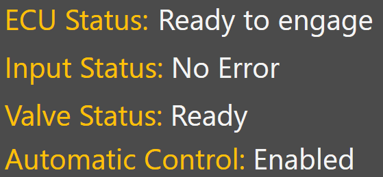
Before tuning, verify the following diagnostic indicators report normal operating status:
- COMMAND ECU Status
- Input Status
- Valve Status
- Automatic Control Diagnostics
Any active faults or invalid status conditions should be corrected before tuning begins.
Tuning Procedure
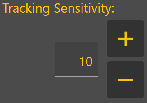
Tuning should always be performed under normal working conditions using the same machine speed, hydraulic flow settings and operating practices that will be used during production work.
Level COMMAND currently provides a single tuning parameter called Tracking Sensitivity. The objective is to achieve stable control while maintaining accurate tracking of the target surface.
- Load a suitable project or design surface.
- Engage Automatic Control.
- Perform several passes under normal operating conditions.
- Observe implement behaviour and control performance.
- Adjust Tracking Sensitivity as required.
- Repeat until the implement follows the target smoothly without excessive lag or oscillation.
During normal grading, the implement should enter the Acquisition Region only briefly before returning to the Tracking Region, where it should remain for most of the grading operation. If the implement spends excessive time acquiring, overshoots repeatedly or oscillates around the target surface, further tuning may be required.
| Adjustment | Typical Effect |
|---|---|
| Increase Tracking Sensitivity | Faster response, more aggressive control, increased risk of overshoot or oscillation. |
| Decrease Tracking Sensitivity | Slower response, smoother control, increased risk of lag and persistent tracking error. |
Understanding Tuning Feedback
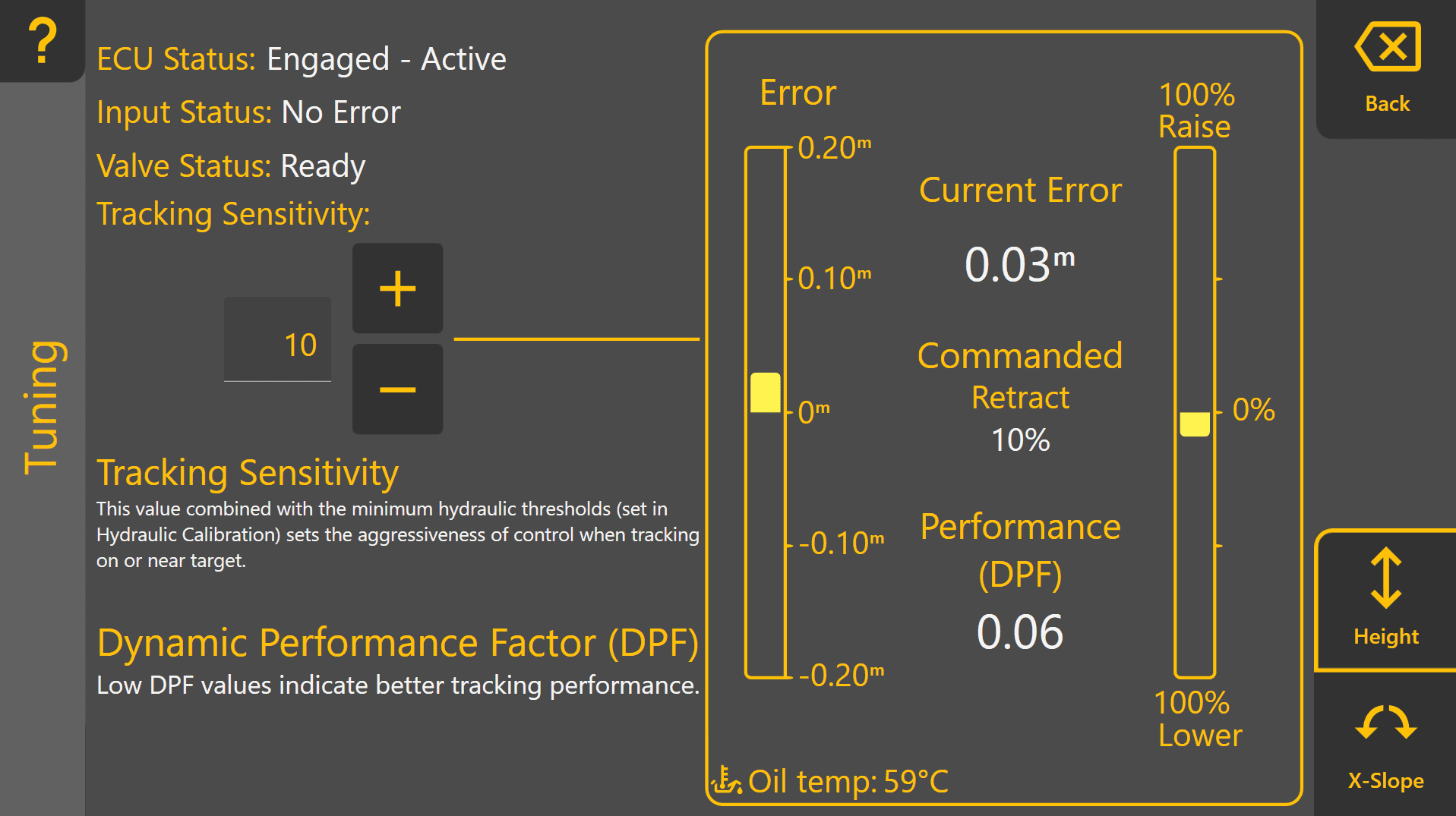
Current Error
Current Error displays the difference between the actual implement position and the target position. Large or persistent error indicates the implement is struggling to follow the target surface accurately.
Commanded Output %
Commanded % displays the control effort being requested by Automatic Control. This value can help identify whether the controller is responding aggressively enough to changing conditions.
Dynamic Performance Factor (DPF)
Dynamic Performance Factor (DPF) is a rolling performance metric used to indicate how closely the implement is following the target surface. A DPF value of 0 represents perfect control performance. Lower DPF values indicate better control performance.
As tracking error, overshoot, oscillation and other control deviations increase, the DPF value will also increase. DPF is calculated using approximately five seconds of Automatic Control performance data and is only updated while Automatic Control is engaged.
DPF should be used as a comparative tuning aid rather than an absolute performance target.
Common Tuning Symptoms
Correct valve calibration—particularly the Min % thresholds—is essential before tuning begins. Incorrect Min % calibration can produce symptoms similar to incorrect Tracking Sensitivity and cannot be corrected through tuning alone.
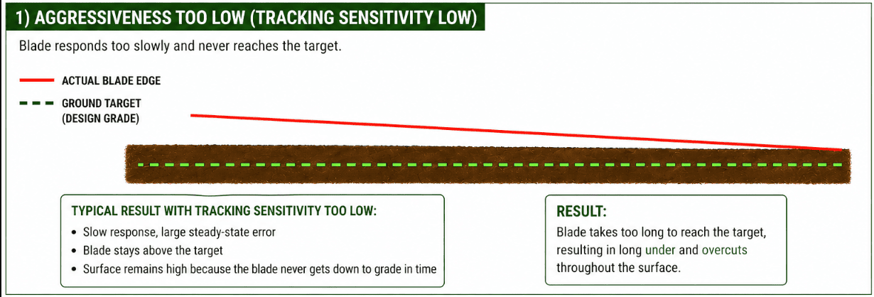
Tracking Sensitivity Too Low
- Implement responds slowly
- Current Error remains visible for extended periods
- Blade struggles to reach target grade
- DPF remains elevated due to persistent tracking error
Recommended Adjustment > Increase Tracking Sensitivity.
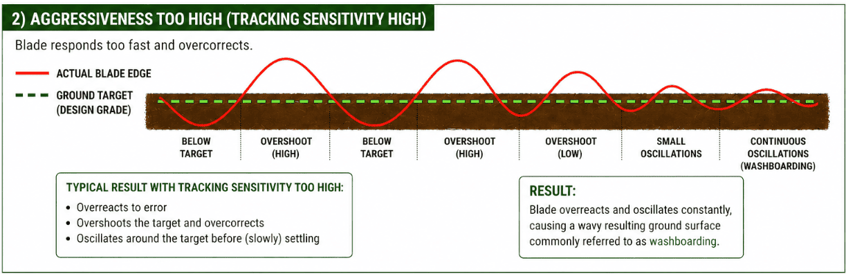
Tracking Sensitivity Too High
- Implement reacts aggressively
- Blade overshoots the target surface
- Oscillation develops
- DPF increases due to instability and overcorrection
Reduce Tracking Sensitivity.
Recommended Adjustment > Reduce Tracking Sensitivity.
Once Automatic Control is performing at an acceptable level, continue on to 3.9 | Validating System Operation.
3.9 | Validating System Operation
Status Validation Checks
Item | Expected Result |
|---|---|
ECU Status | Connected and operating normally |
GNSS Status | Fixed RTK solution |
Position Accuracy | Within expected limits |
Inertial Sensors | Reporting valid data |
Valve Outputs | Available and responding |
Machine Configuration | Correct implement selected |
Active Faults | None present |
If any item fails, correct the issue before proceeding.
Manual Hydraulic Validation
Verify manual hydraulic operation is as expected before engaging automatic control.
- Raise and lower the implement using manual controls.
- Confirm smooth movement.
- Confirm correct movement direction.
- Confirm full travel can be achieved.
- Verify no unexpected hydraulic behaviour occurs.
Expected Result:
- Implement responds immediately.
- Movement direction matches commanded direction (Up/Down/Left/Right).
- No instability or oscillation is present.
Automatic Control Engagement Validation
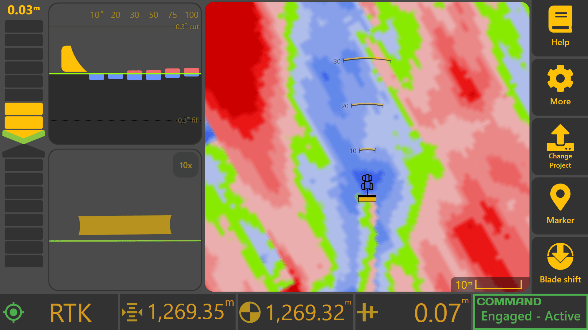
Verify Automatic Control can engage and operate correctly:
- Position the machine in a safe operating area.
- Load a valid design surface.
- Satisfy all engagement requirements.
- Engage Automatic Control.
Expected Result:
- Automatic Control engages successfully.
- No engagement warnings are generated.
- Control outputs become active.
Automatic Control Response Validation
Verify control outputs produce the expected machine response when Automatic Control is active.
- Engage Automatic Control on the previously loaded design surface.
- Observe implement movement.
Expected Result:
- Implement moves toward the design surface.
- Movement direction is correct.
- Correction occurs without hesitation.
- No excessive overshoot occurs.
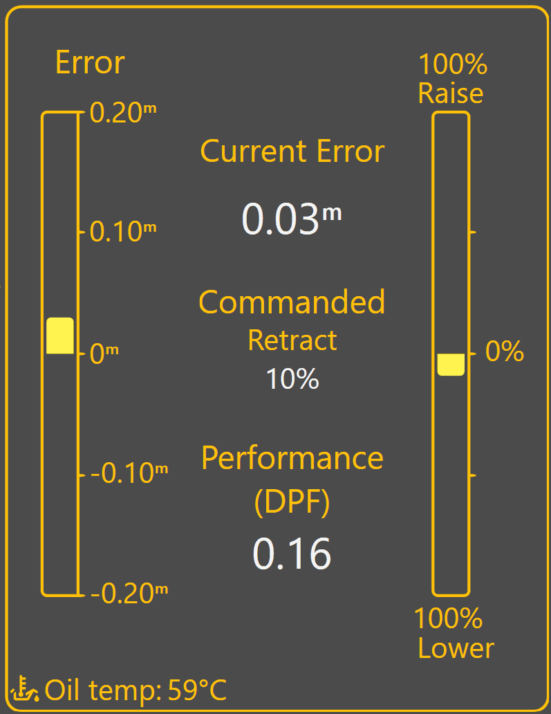
Grade Tracking Validation
Operate the machine under normal working conditions. Navigate to More > COMMAND Settings > Tuning.
Observe:
- Current Error
- Commanded Output %
- Dynamic Performance Factor (DPF)
Expected Result:
- Current Error remains stable and controlled.
- Commanded Output % changes smoothly.
- DPF remains low and consistent.
- Automatic Control maintains the design surface without oscillation.
Commissioning Acceptance Checklist
Validation Item | Pass |
|---|---|
ECU communicating successfully | ☐ |
GNSS selected and stable with RTK Fix | ☐ |
X-Slope sensor angle values updating correctly | ☐ |
Hydraulic outputs verified | ☐ |
Cylinder calibration completed | ☐ |
Automatic Control engages correctly | ☐ |
Control direction verified | ☐ |
Tracking Sensitivity tuned | ☐ |
Grade tracking validated | ☐ |
Automatic Control performance acceptable | ☐ |
No active faults present | ☐ |
Once all validation checks have been completed successfully and Automatic Control performance has been verified, the machine is ready for operator training and production use.
Dealer installation and commissioning is now complete. Continue to Section 4 | Operator Quick Start for guidance on day-to-day operation of Level COMMAND.
4 | Operator Quick Start
The purpose of this chapter is to guide operators through the basic workflow of using Level COMMAND, from system startup through to performing the first pass safely and confidently.
4.1 | System Startup
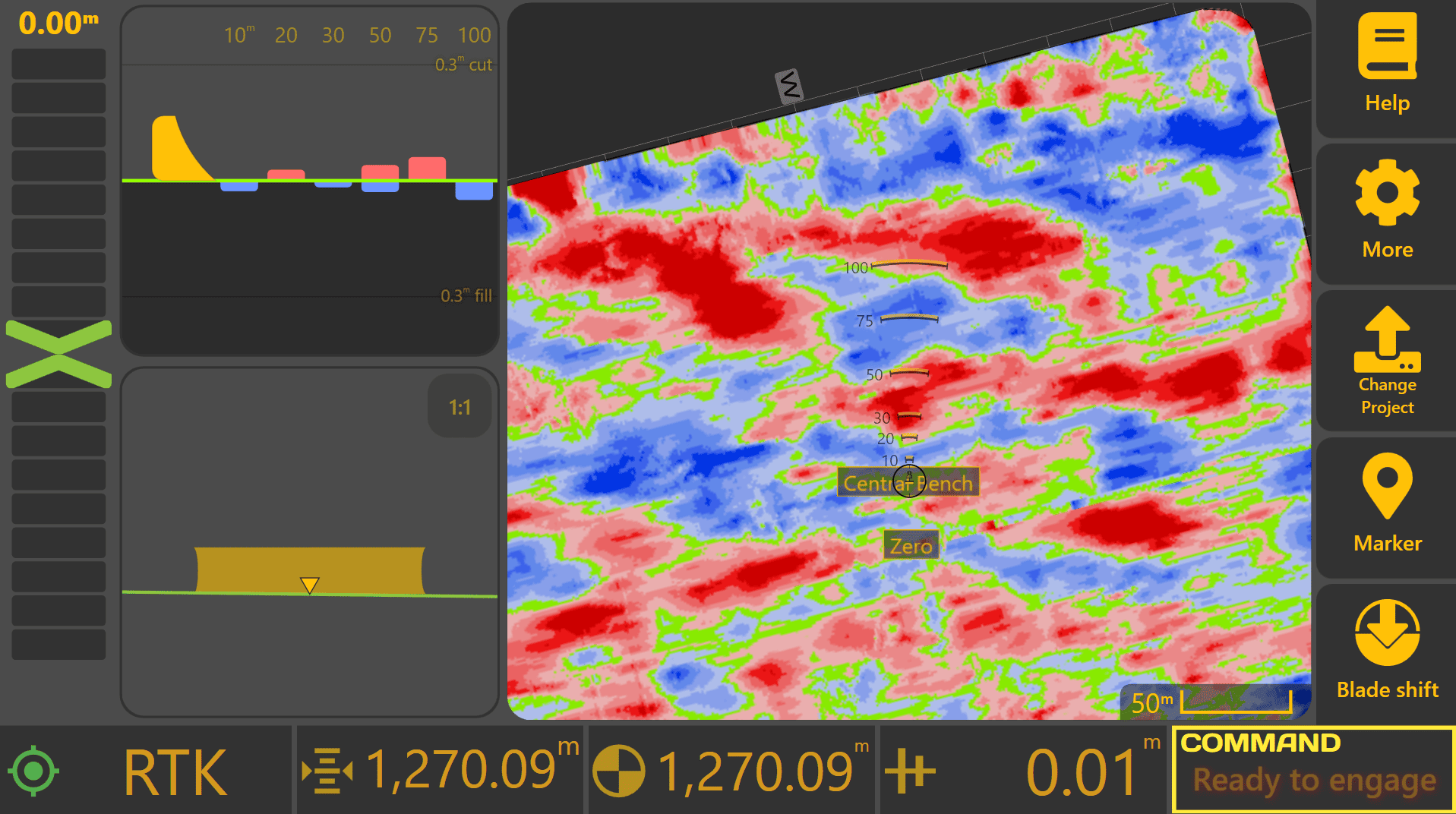
When Level COMMAND is first started, the Apply View will be displayed. Before loading a project or attempting to engage Automatic Control, perform the following readiness checks.
Verify GNSS Operation
Once the machine is powered on, allow the GNSS receiver(s) several minutes to initialise and obtain RTK corrections.
GNSS status can be checked using either:
- The GNSS status widget on the Apply View.
- More → COMMAND Settings → Inputs / Offsets.
If using the Inputs / Offsets page, verify that each configured GNSS receiver displays a Fix Type of RTK before proceeding.
Automatic Control requires RTK-quality positioning for accurate operation. Lower quality fix types such as GPS, Differential GPS or Float RTK may reduce positioning accuracy and automatic control performance. To prevent inaccurate machine control, the COMMAND ECU will not allow Automatic Control to engage unless all required GNSS receivers have achieved an RTK fix.
If RTK fix type has not been achieved after several minutes, common causes include:
- GNSS receiver still initialising.
- RTK radio or correction service unavailable.
- Poor antenna visibility due to nearby trees, buildings or obstructions.
- Incorrect GNSS receiver configuration.
- Damaged or disconnected GNSS hardware.
Refer to Section 3 | Dealer Installation & Commissioning if GNSS configuration requires adjustment.

Check COMMAND Status
Once GNSS operation has been verified, review the COMMAND Status indicator shown at the bottom-right of the Apply View.
The COMMAND Status provides information about the current operating state of the system, including whether:
- Additional setup is required.
- Automatic Control is ready to engage.
- A warning or fault condition is present.
If the system has not previously been configured or commissioned, consult your dealer or refer to Section 3 | Dealer Installation & Commissioning.
Continue to 4.2 | Understanding COMMAND Status for detailed information about the status indicator and its various operating states.
4.2 | Understanding COMMAND Status
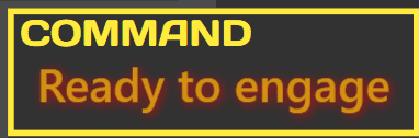
The COMMAND Status area is shown at the bottom-right of the Apply View and provides a quick indication of the current operating state of the COMMAND ECU.
Operators should check COMMAND Status before attempting to engage Automatic Control. The status message indicates whether the system is ready to engage, currently engaged, waiting for an operator action, or unable to operate due to a warning, fault or incomplete setup condition.
Status Colours
The coloured frame around the COMMAND Status area provides a quick visual indication of the current system state:
- Green indicates that Automatic Control is currently engaged.
- Yellow indicates that all requirements have been satisfied and the system is ready for Automatic Control engagement.
- Red indicates that operator action, further setup or fault correction is required before Automatic Control can operate normally.


Typical Workflow
Before engaging Automatic Control:
- Confirm GNSS has achieved RTK fix.
- Confirm the correct project or design surface is loaded.
- Check COMMAND Status.
- Resolve any warnings or required actions.
- Engage Automatic Control only when COMMAND Status shows Ready to Engage.
Green Statuses - Automatic Control Engaged
Green statuses indicate that Automatic Control is currently engaged.
| Status | Meaning | Operator Action |
|---|---|---|
| Engaged - Active | Automatic Control is engaged and COMMAND may move the implement automatically. | Continue operating normally. |
| Engaged - Low Speed | Automatic Control is engaged, but the machine is moving too slowly for COMMAND to move the implement. | Increase machine speed above 0.2 km/h to allow automatic implement movement. |
| Engaged - Calibrating | COMMAND is controlling the implement as part of a calibration process. | Continue the calibration procedure shown on screen. |
Yellow Statuses - Ready for Engagement
Yellow statuses indicate that the system is ready for Automatic Control, but Automatic Control is not currently engaged.
| Status | Meaning | Operator Action |
|---|---|---|
| Ready to Engage | The system is ready for Automatic Control. | Press the engage button when ready to begin. |
Red Statuses - Operator Attention Required
Red statuses indicate that operator action, additional setup or fault correction is required before Automatic Control can operate.
| Status | Meaning | Operator Action |
|---|---|---|
| Waiting for RTK | The GNSS receiver does not have RTK correction yet. | Wait for RTK. Check GNSS corrections and receiver setup if RTK is not achieved after several minutes. |
| No Connection to ECU | Level COMMAND cannot communicate with the COMMAND ECU. | Check ECU power, wiring and connections. |
| Blade Width Unset | The selected machine profile has not been fully configured. | Contact your dealer or complete machine setup before continuing. |
| Waiting for Manual SCV Input | The tractor requires the hydraulic control lever to be moved before Automatic Control can operate. | Briefly move the required hydraulic control lever. |
| System Not Armed | Automatic Control has not been armed. | Turn the arm/engage switch on, or cycle it off and back on if required. |
| SCV Locked | The tractor hydraulic valve is locked and cannot be controlled by COMMAND. | Unlock the required hydraulic valve using the tractor controls. |
| Speed Too Fast | Machine speed is above the maximum allowed Automatic Control speed. | Reduce machine speed before engaging Automatic Control. |
| Waiting for IMU Data | COMMAND is not receiving data from the IMU sensor. | Check IMU power, wiring and configuration. |
| Unstable GPS / IMU | GNSS or IMU data is changing too quickly or appears invalid. | Stop and allow the system to stabilise. Check sensor mounting and signal quality if the warning remains. |
| NMEA Low Rate | GNSS position updates are arriving slower than expected. | Check GNSS receiver settings and connections. |
| T3 Timeout | COMMAND has stopped receiving control information from Level COMMAND. | Check the tablet, software and ECU connection. |
| No Active Control Valves | No hydraulic valves have been assigned to the active control function. | Complete machine setup or contact your dealer. |
| Check Calibration | Hydraulic calibration has not been completed. | Complete the calibration process before continuing. |
| Valve Error | A hydraulic valve or valve output has reported an error. | Check valve wiring, configuration and hydraulic hardware. |
| No Main License | Level COMMAND is not licensed for operation. | Enter a valid software unlock code. |
| Var Reset Required | The ECU requires additional setup after a firmware update. | Contact your dealer or T3RRA Support. |
Ready To Continue
Once COMMAND Status shows Ready to Engage, the system is ready for Automatic Control engagement.
Continue to 4.3 | Loading or Importing a Project if a project has not yet been loaded, or continue to 4.5 | Engaging Automatic Control if the project and zero reference are already prepared.
4.3 | Loading or Creating a Project
Loading a Design File
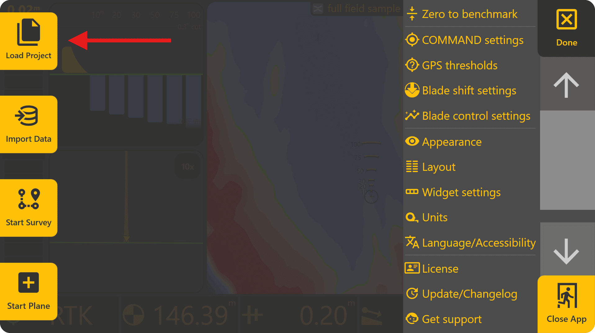
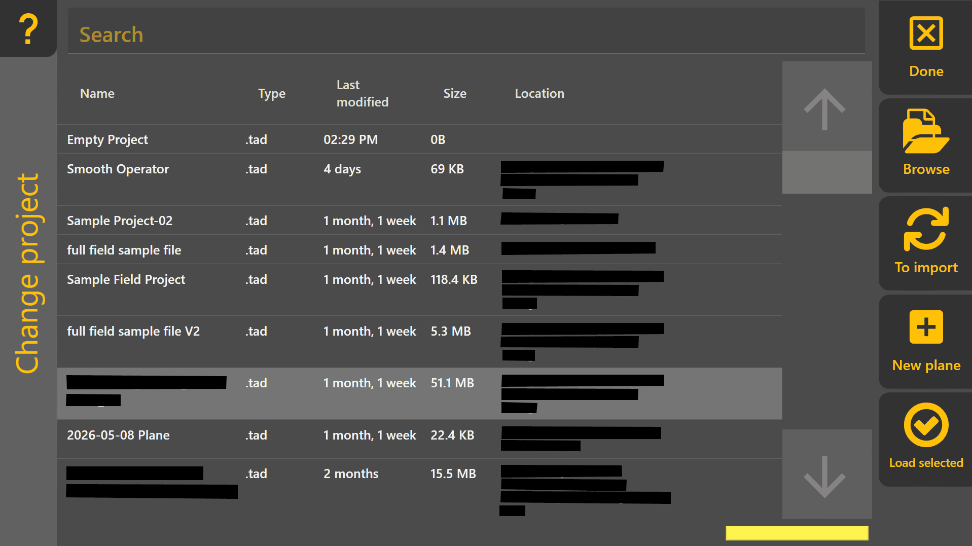
To load a design file, press Done at the top-right to return to the Level COMMAND apply page, then press More > Load Project. This will open the Change Project page and display all .tad file projects. This file type is specific to LC and the software will automatically scan the file system to find all .tad files present - alternatively to find them manually press "Browse" on the right side of the screen.
Supported design formats:
• T3RRA Project (.tci)
• GPS Design (.gps)
• Existing Level COMMAND Plane Projects
 Loading an Existing Level COMMAND Project
If loading an existing Level COMMAND project (.tad file type), select it from the list and press Load Selected.
Loading an External Design File (Other File Types)
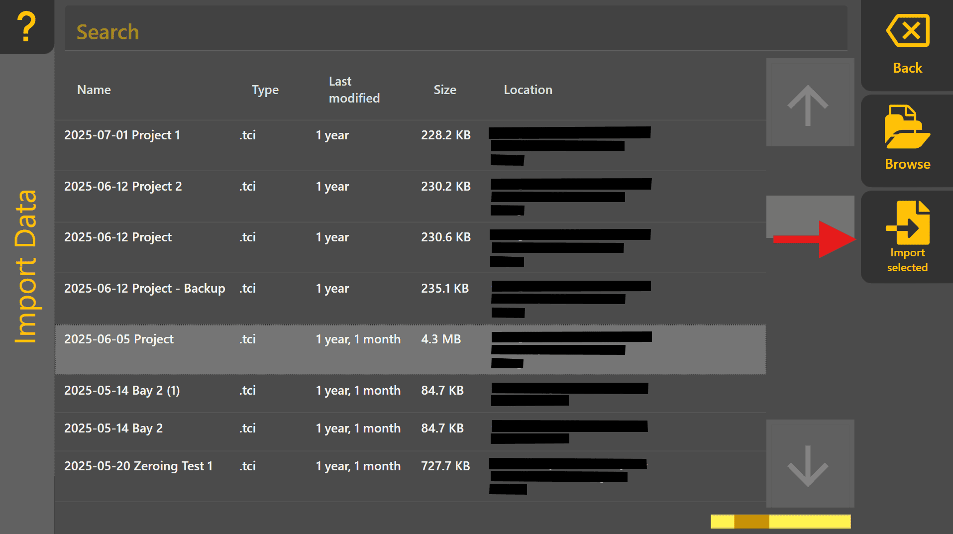
If loading a design of different file type, such as .tci, press "To Import" to move to the Import Data page. Select the design file from the list and then press "Import Selected".
Creating a Basic Plane Project
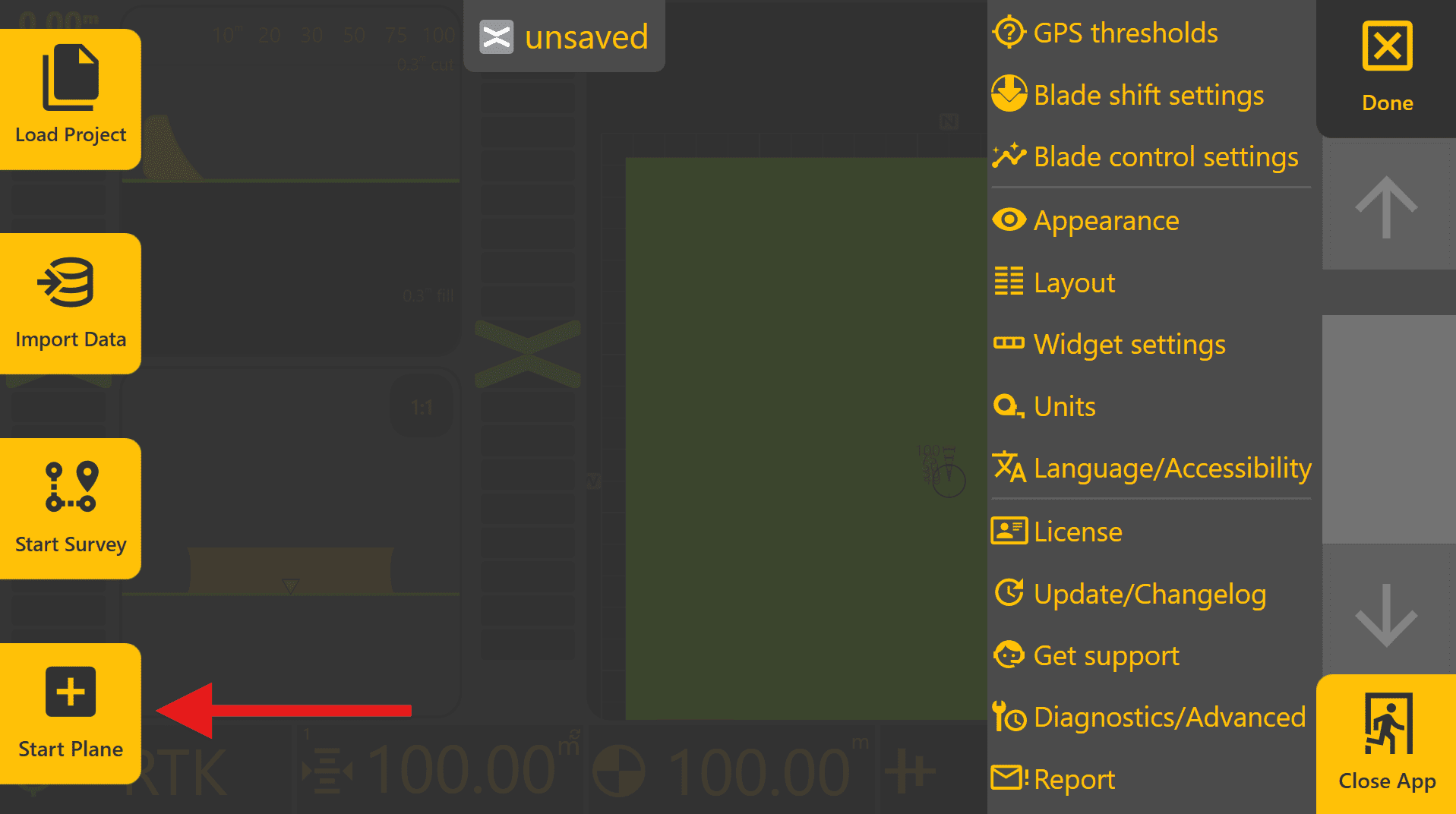
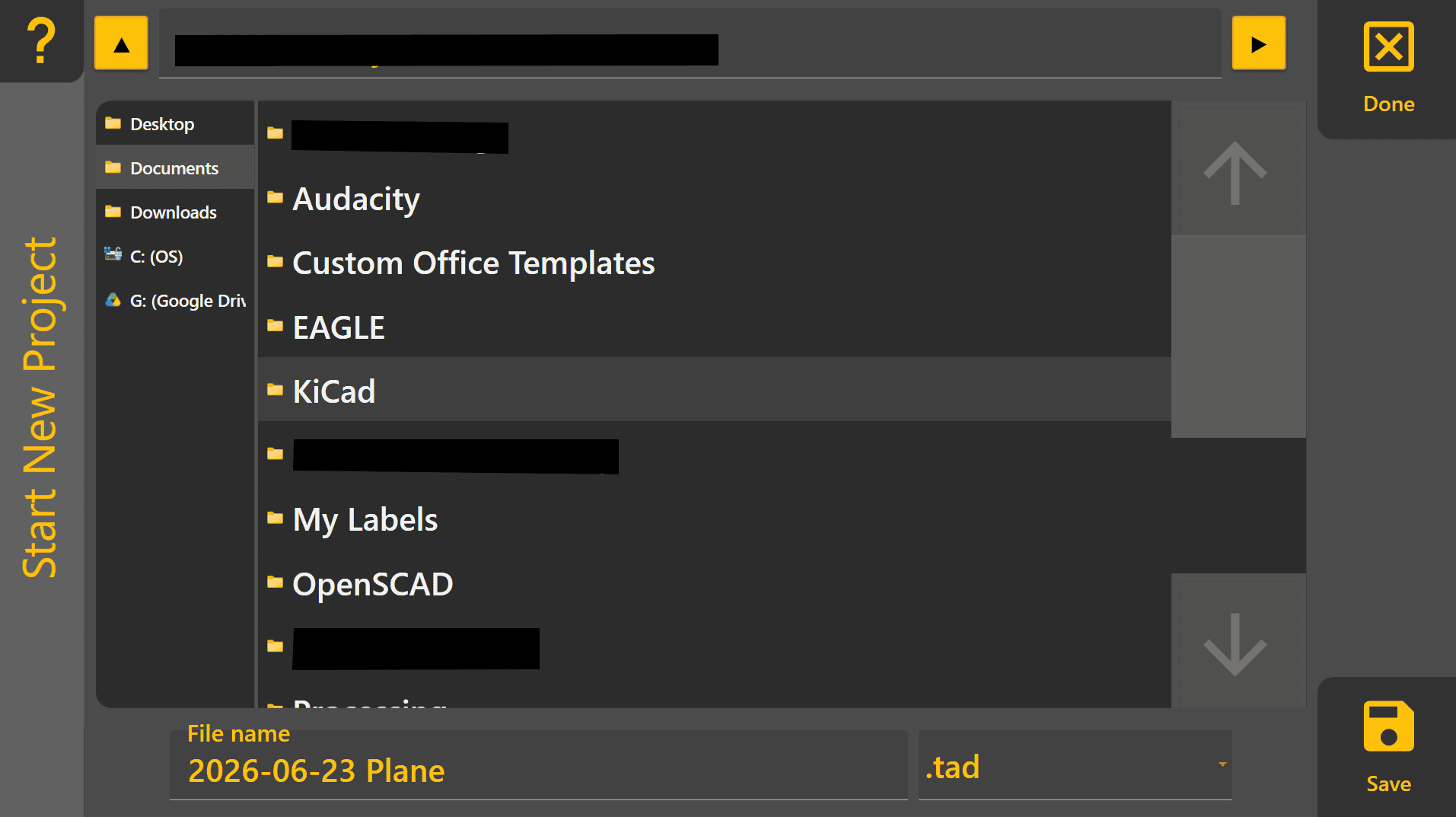
A Plane project is the quickest way to begin using Level COMMAND without importing an existing design. Plane projects are commonly used for machine testing, simple levelling work and creating flat pads. To create a basic 2D/3D plane project, begin by pressing More > Start Plane. Choose an appropriate location to save the plane project on the tablet PC and then name the project, then press "Save".
To begin designing a Plane:
- Press Planes, then select one of the available Plane slots.
- Press Create.
- Press Origin and then Use GPS to set the Plane origin to the current implement position.
- Press Okay to create a flat Plane surface.
The Plane can now be loaded and used for testing or levelling work.
If a sloped surface is required, press Slope and use Use GPS at a second location to automatically calculate the desired slope.
For detailed information on Plane projects, refer to Section 5 | Operational Workflows
4.4 | Setting Zero
What is Zeroing?
Zeroing aligns the machine to the design surface so that Level COMMAND can guide the implement to the correct elevation.
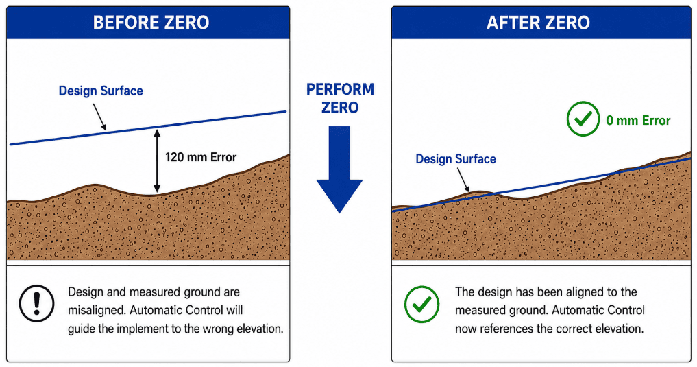
A valid zero is required before Automatic Control can operate accurately. If the machine is not correctly zeroed, Level COMMAND may display incorrect cut and fill values and guide the implement to the wrong elevation.
A valid zero should be established whenever:
-
Beginning a new project.
-
Returning to a project after an extended period of time.
-
Changing or relocating the GNSS base station.
-
Performing major project alignment or terrain alignment changes.
Different project types may require different zeroing methods. The most common workflows are described below.
Benchmark Markers
 Level COMMAND separates markers into two categories:
-
Benchmark Markers – Used for project alignment and zeroing.
-
General Markers – Used for recording locations and points of interest within a project.
Only Benchmark Markers can be selected when performing a benchmark zero. This helps prevent accidental alignment to an incorrect marker.
Benchmark Markers may be:
-
Imported as part of a design file.
-
Created manually using the Create Benchmark option when creating a Marker.
-
Generated automatically when creating Plane Origins.
Because Plane Origins are stored as Benchmark Markers, they can be used later when re-zeroing a Plane Project.
Zeroing a Plane Project

Plane Projects are normally zeroed during creation of the Plane itself.
When the Plane Origin is created using Use GPS, the Plane surface is aligned to the current implement position and elevation. If the Primary and Secondary Slopes are also defined using GPS positions, the Plane surface will automatically be aligned to those locations as well.
In most situations no further zeroing is required. However, if the project is reopened later or a different base station is being used, the Plane may need to be re-aligned.
To re-zero a Plane Project:
-
Position the implement at the Plane Origin.
-
Place the implement on the ground surface.
-
Press More → Zero to Benchmark.
-
Select the Plane Origin marker.
-
Press Zero.
The Plane Origin will be adjusted to match the current implement position and elevation.
By default, only elevation is adjusted. Latitude and Longitude can also be adjusted if required by disabling the Elevation Only option.
Zeroing a Design with a Benchmark
Many imported designs contain one or more surveyed benchmark locations. A benchmark is a known reference point that can be used to accurately align the machine with the design.
To zero using a benchmark:
-
Move the machine to the benchmark location.
-
Place the implement on the benchmark surface.
-
Press More → Zero to Benchmark.
-
Select the desired Benchmark Marker.
-
Press Zero.
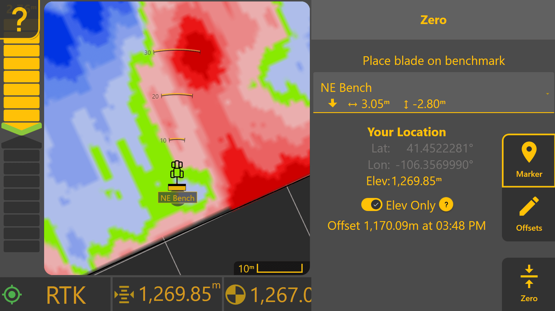
Level COMMAND will record and average approximately 30 seconds of GNSS data before applying the alignment. Once complete, verify that cut and fill values appear reasonable before beginning work.
Zeroing a Design without a Benchmark
If a design does not contain a benchmark, one should be created before beginning work.
Choose a location that:
-
Is easy to locate again later.
-
Will remain undisturbed throughout the project.
-
Represents a stable reference point.
- Is a wide area where the implement can be manoeuvred easily and positioned accurately on the marker.
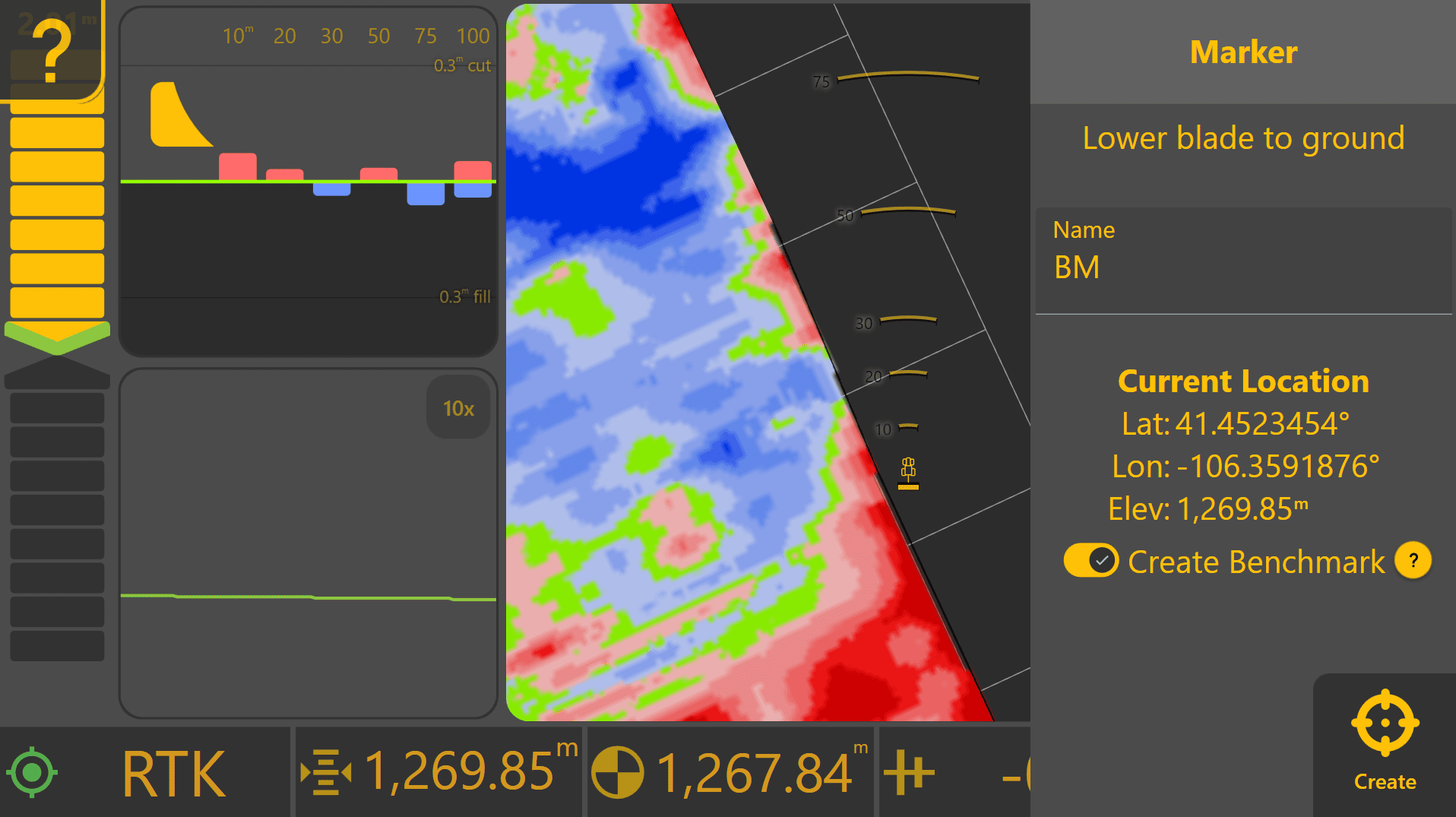
To create a Benchmark Marker:
-
Press Marker from the Apply View.
-
Enter a name such as Benchmark, Bench, BM or MB.
-
Enable Create Benchmark.
-
Press Create.
Once the Benchmark Marker has been created, perform the standard benchmark zeroing procedure described above for zeroing a design with a benchmark.
Zeroing to an Existing Surface (Advanced)
In some situations it may be desirable to align a design to an existing surface rather than a surveyed benchmark.
This method is commonly used when:
Choose an area that:
-
Has not been disturbed.
-
Is known to be on grade.
-
Can be located again later if required.
- Is a wide area where the implement can be manoeuvred easily and positioned accurately on the marker.
To align the design:
-
Position the implement on the chosen location.
-
Press More → Zero to Benchmark.
-
Press Offsets.
-
Press Set Z to Current.
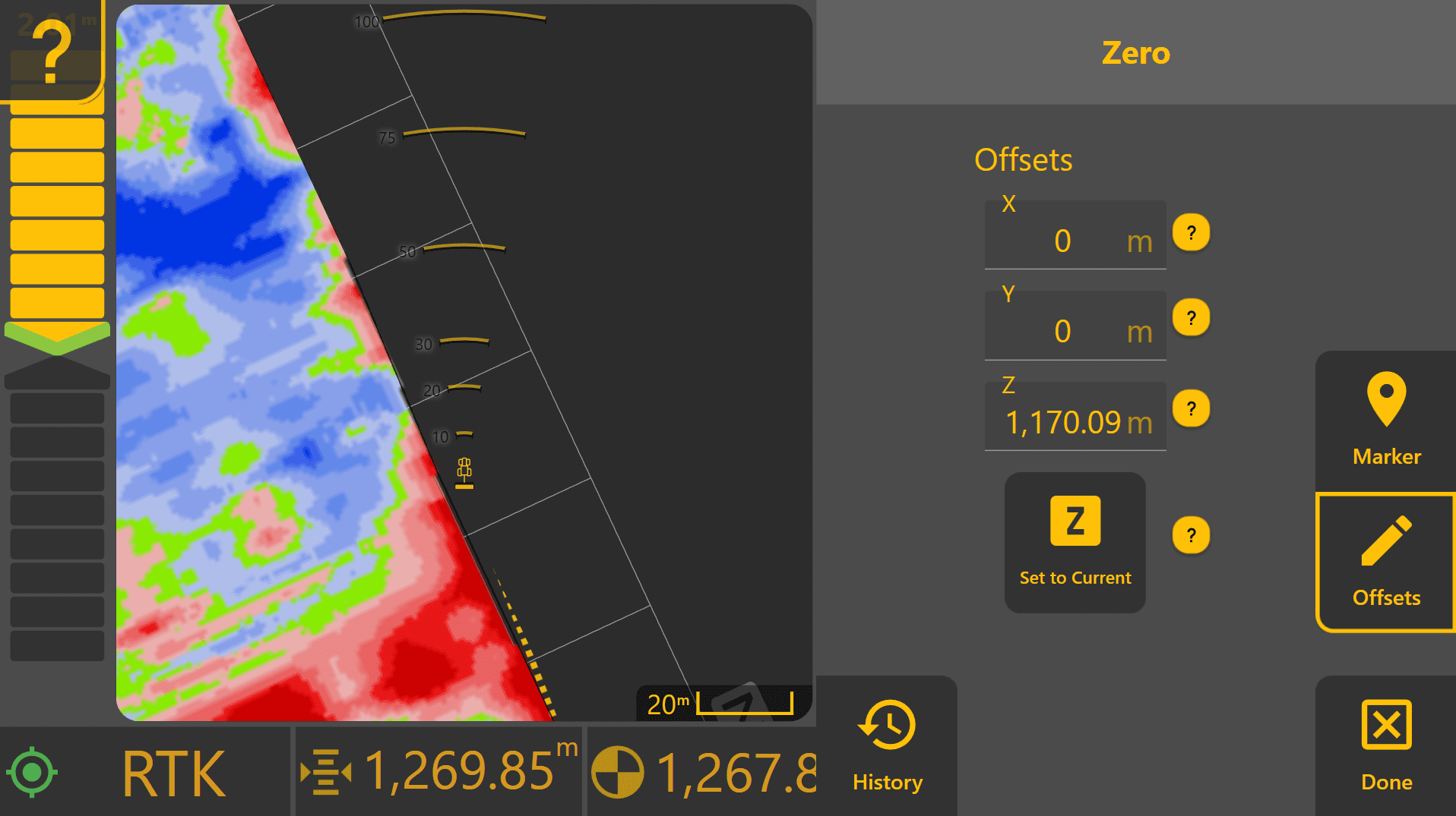
The design will be shifted vertically so that the current location becomes the new zero reference. Creating a marker at this location is highly recommended so it can be revisited later for verification, or re-zeroed using the Zeroing a Design with a Benchmark process described above.
Ready to Continue
Before engaging Automatic Control, verify that:
✓ A project is loaded.
✓ GNSS receivers have achieved RTK fix.
✓ COMMAND Status shows Ready to Engage.
✓ A valid zero has been established.
Continue to 4.5 | Engaging Automatic Control.
4.5 | Engaging Automatic Control
Before Engaging Automatic Control
Before engaging Automatic Control, verify that:
✓ A project is loaded.
✓ GNSS receivers have achieved RTK fix.
✓ A valid zero has been established.
✓ COMMAND Status displays Ready to Engage.
Ready to Engage indicates that all Level COMMAND and COMMAND ECU requirements have been satisfied and Automatic Control is available for engagement.
If COMMAND Status displays any other message, refer to 4.2 | Understanding COMMAND Status or the Troubleshooting chapter before continuing.
Arming the System

COMMAND installations use a three-position Arm/Engage switch:
Off → Armed → Engage (momentary)
The switch must be placed in the Armed position before Automatic Control can be engaged.
If COMMAND Status displays System Not Armed, verify that:
-
The Arm/Engage switch is in the Armed position.
-
The machine has not been restarted since arming the system.
-
The switch has not been accidentally moved to Off.
If necessary, cycle the switch to Off and then back to Armed.
Engaging Automatic Control

Once COMMAND Status displays Ready to Engage, momentarily press the Engage position of the Arm/Engage switch.
COMMAND Status will change to one of the following states:
Engaged - Active
Automatic Control is engaged and COMMAND may actively move the implement to follow the design surface.
Engaged - Low Speed
Automatic Control is engaged, but implement movement is currently disabled because machine speed is below 0.2 km/h.
Once machine speed increases above 0.2 km/h, COMMAND will automatically begin controlling the implement if cut/fill error is present.
Hydraulic Valve Activation
The Engage switch enables Automatic Control within the COMMAND ECU. Depending on the hydraulic system being used, additional tractor or machine controls may also need to be placed into automatic mode.
Common examples include:
-
Placing a tractor SCV / Auxiliary valve into detent mode.
-
Pushing an electronic SCV / Auxiliary valve lever past its normal travel to activate automatic operation.
-
Enabling machine-specific hydraulic automation functions.
If Automatic Control appears to engage correctly but no hydraulic movement occurs, verify that the hydraulic valve system has also been placed into automatic mode.
Disengaging Automatic Control
To disengage Automatic Control, momentarily press the Engage switch again.
COMMAND Status will return to Ready to Engage.
Automatic Control can then be re-engaged at any time by pressing the Engage switch again.
Automatic Disengagement
Automatic Control may automatically disengage if critical operating conditions are no longer satisfied.
Common causes include:
-
Loss of RTK positioning.
-
GNSS or sensor communication issues.
-
Hydraulic valve faults.
-
Loss of communication between Level COMMAND and the COMMAND ECU.
-
Machine-specific safety conditions.
If Automatic Control disengages unexpectedly, check COMMAND Status for additional information.
The last disengagement reason can also be viewed from the Apply View by pressing More → COMMAND Settings → Diagnostics.
Calibration Mode
When performing valve calibration, COMMAND Status may display Engaged - Calibrating.
In this mode, hydraulic movement will only occur while the operator is actively holding the Engage switch during a calibration test.
Releasing the Engage switch immediately stops movement. This behaviour provides an additional level of safety while calibrating hydraulic functions.
What to Expect During First Engagement
When Automatic Control is engaged for the first time:
-
The implement may not move immediately if it is already close to the design surface.
-
Small corrections may occur as COMMAND begins reducing cut/fill error.
-
Implement movement should become smoother as machine speed increases and consistent GNSS data is maintained.
-
Larger cut/fill errors will generally result in larger hydraulic commands.
Observe machine behaviour during the first pass and verify that implement movement matches the expected design direction.
If the implement consistently moves in the wrong direction, disengage Automatic Control immediately. The hydraulic valve extend/retract direction may need to be corrected using Swap Extend/Retract from More → COMMAND Settings → Valve Cals. Refer to the commissioning or troubleshooting sections if unsure.
Ready to Continue
Once Automatic Control can be engaged successfully and the implement responds correctly, continue to 4.6 | Performing Your First Pass.
4.6 | Performing Your First Pass
Understanding the Operator's Role
Level COMMAND automatically controls the implement to follow the selected design surface, but it does not decide where material should be moved from or where it should be placed.
The operator remains responsible for planning the earthmoving operation, including:
-
Selecting suitable cut and fill areas.
-
Determining haul directions and travel paths.
-
Deciding where material should be sourced from.
-
Deciding where material should be placed.
Careful planning can significantly improve productivity by reducing unnecessary material movement and minimising rework. Material that is moved multiple times before reaching its final location increases both operating time and fuel consumption.
Monitoring Automatic Control
Once Automatic Control is engaged, monitor the Apply View to verify that COMMAND is operating as expected.
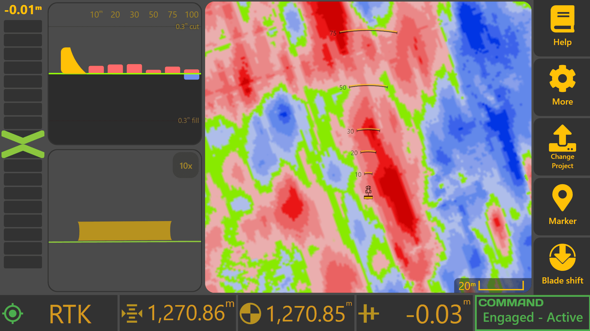
Important indicators include:
Error Chevron
The Error Chevron indicates whether the implement is above or below the design surface. As Automatic Control operates, the Error Chevron should generally move toward zero as the design elevation is approached.
Cross Section View
If using both Height and X-Slope control, monitor the Cross Section View to verify that both elevation and cross-fall are tracking correctly.
Cut/Fill Information
Monitor upcoming cut and fill values to understand how much material is approaching. Large cut or fill values may require a different operating strategy than smaller corrections.
Understanding the Control Profile
 The Control Profile provides a visual representation of the current Automatic Control target and implement position.
To display the Control Profile, press Blade Shift from the Apply View. The Control Profile will appear on the right side of the screen.
The profile displays:
Original
The original surveyed surface elevation.
Target
The elevation that Automatic Control is currently attempting to achieve.
Design
The final design elevation.
Current
The current measured implement elevation.
As Automatic Control operates, the Current position should generally move toward the Target position.
If Dynamic Cut Limit or Dynamic Fill Limit is active, the Target position may intentionally differ from the Design elevation. The shaded area of the Control Profile indicates material that will not be cut or filled during the current pass.
Using Blade Shift
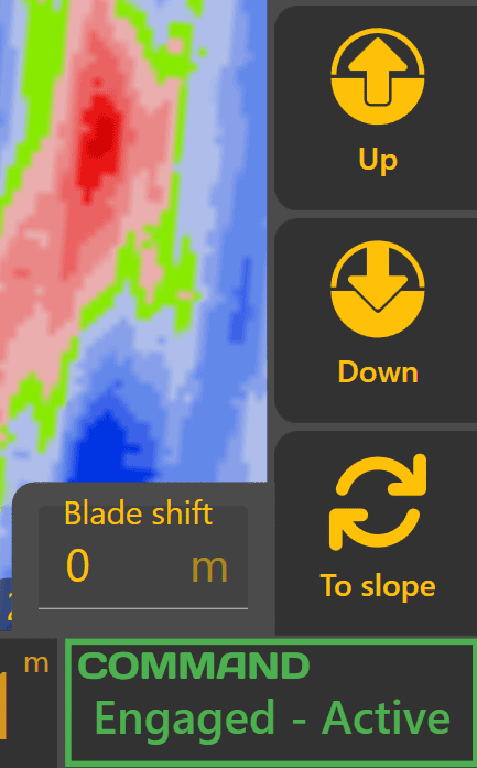
Blade Shift allows the operator to temporarily raise or lower the Automatic Control target without modifying the underlying design surface.
Use the Up and Down buttons to adjust the shift value.
Common uses include:
-
Leaving additional material for later trimming.
-
Reducing cutting depth during difficult conditions.
-
Making temporary grading adjustments without changing the design.
Blade Shift affects Automatic Control behaviour only and does not modify the design file.
Using Cut/Fill Limit
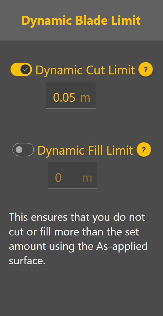
Cut/Fill Limiting allows Automatic Control to progressively work toward the design surface over multiple passes.
To access Cut/Fill Limiting:
-
Press Blade Shift.
-
Press Blade Limit.
-
Enable Dynamic Cut Limit and/or Dynamic Fill Limit.
-
Enter the desired limit value.
For example:
A Dynamic Cut Limit of 0.05 m will cause Automatic Control to target only 5 cm of cut during each pass, even if the full design requires a larger cut.
This can assist with:
-
Reducing blade loading.
-
Preventing machine overload.
-
Improving material control.
-
Maintaining smoother machine operation.
Multiple passes may be required to reach final grade when Cut/Fill Limiting is enabled.
Changing Surface Display Modes
Different map layers can be displayed depending on the information required.
Display settings can be changed from:
More → Appearance
Common display modes include:

Design
Displays the intended finished design surface.
 As Elevation

Displays the measured surface elevation collected during operation.
 As Cut/Fill
Displays current cut and fill values based on the latest surveyed surface.
The As Elevation and As Cut/Fill layers update dynamically as work progresses, making them useful for monitoring grading performance during operation.
Signs That Automatic Control Is Working Correctly
During normal operation:
-
The Error Chevron generally trends toward zero.
-
The Current value in the control profile moves toward the Target value.
-
The worked area updates on the map.
-
The finished surface visually matches the displayed cut/fill changes.
-
COMMAND Status remains Engaged - Active.
If Performance Appears Incorrect
If the implement appears slow to respond, struggles to reach grade or behaves erratically, verify that commissioning and calibration have been completed correctly.
Common causes include:
-
Incorrect valve calibration.
-
Hydraulic systems not placed into automatic mode.
-
Poor GNSS quality.
-
Tracking Sensitivity requiring adjustment.
Tracking Sensitivity controls the overall aggressiveness of Automatic Control:
-
Values that are too low may result in slow response and difficulty reaching target grade.
-
Values that are too high may result in excessive corrections and unstable implement movement.
If required, adjust Tracking Sensitivity in small increments and observe the resulting behaviour.
Verifying the Completed Pass
Once a pass has been completed, inspect both the worked surface and the map display. The completed area should generally show reduced cut/fill values and move closer to on-grade conditions. Multiple passes may be required where large cut or fill values are present.
In some situations, manual intervention may still be required to relocate material efficiently between cut and fill areas.
Confirming Surface Accuracy
Inspect the completed surface and check for:
-
Washboarding.
-
Dips.
-
High spots.
-
Surface irregularities.
If concerns remain about the accuracy of the completed work, a survey may be performed and compared against the updated surface displayed within Level COMMAND.
Ready to Continue
Once Automatic Control is producing smooth implement movement and the completed surface matches expectations, continue operating normally.
Refer to Chapter 5 for additional operational workflows and Chapter 6 for detailed information on Automatic Control behaviour. Continue on to 4.7 | Closing Level COMMAND.
4.7 | Closing Level COMMAND
Before Closing Level COMMAND
Before closing Level COMMAND, verify that:
✓ Automatic Control has been disengaged.
✓ Hydraulic functions have been returned to manual operation.
✓ The machine is in a safe operating condition.
✓ The implement has been lowered safely to the ground where appropriate.
If COMMAND Status shows Engaged - Active or Engaged - Low Speed, disengage Automatic Control before continuing.
Saving Your Work
Projects, design files, Plane surfaces, markers and configuration changes are saved automatically as they are created or modified. In normal operation, no manual save process is required before exiting Level COMMAND.
Although work is saved automatically, it is good practice to close Level COMMAND before shutting down the tablet or PC.
If you wish to manually save a copy of the current project:
- Press More.
- Press the current project name at the top of the window.
- Press Save As.
- Select the desired save location.
- Press Save.
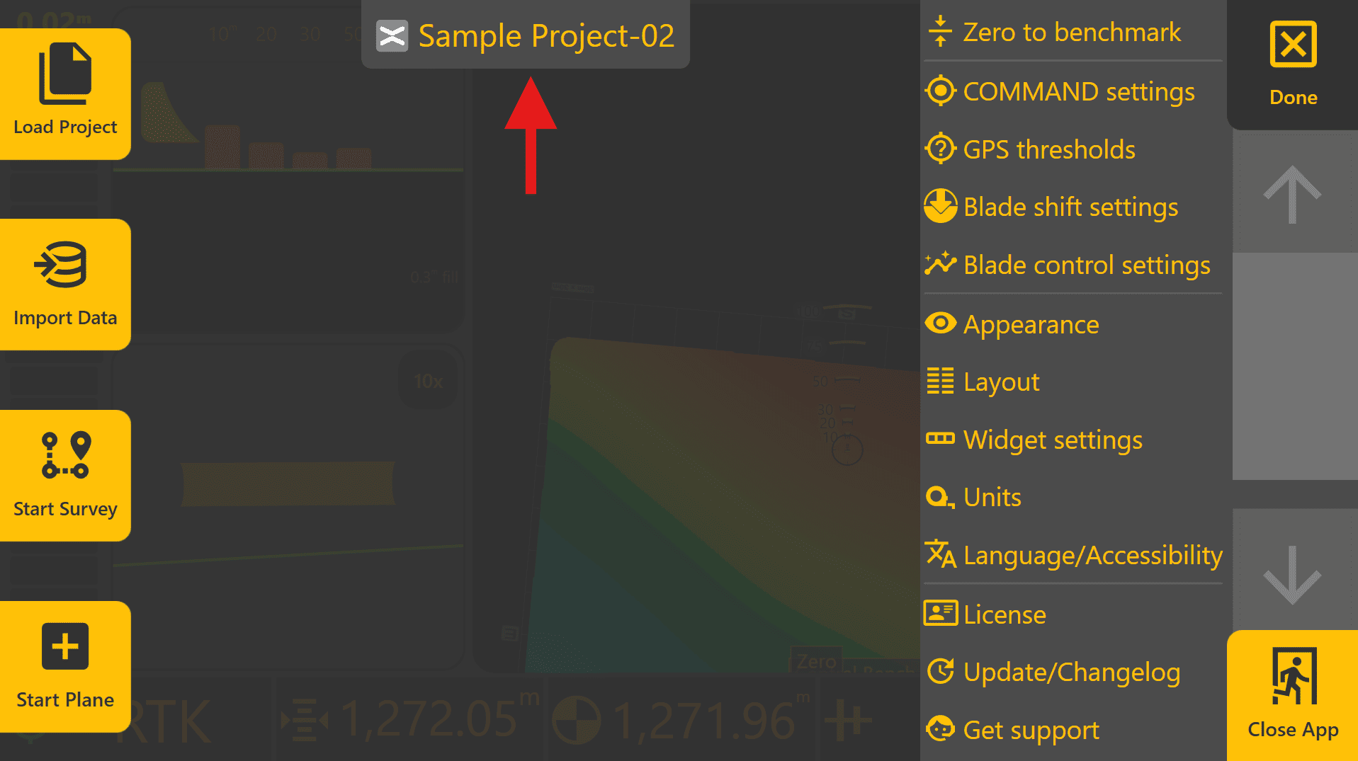
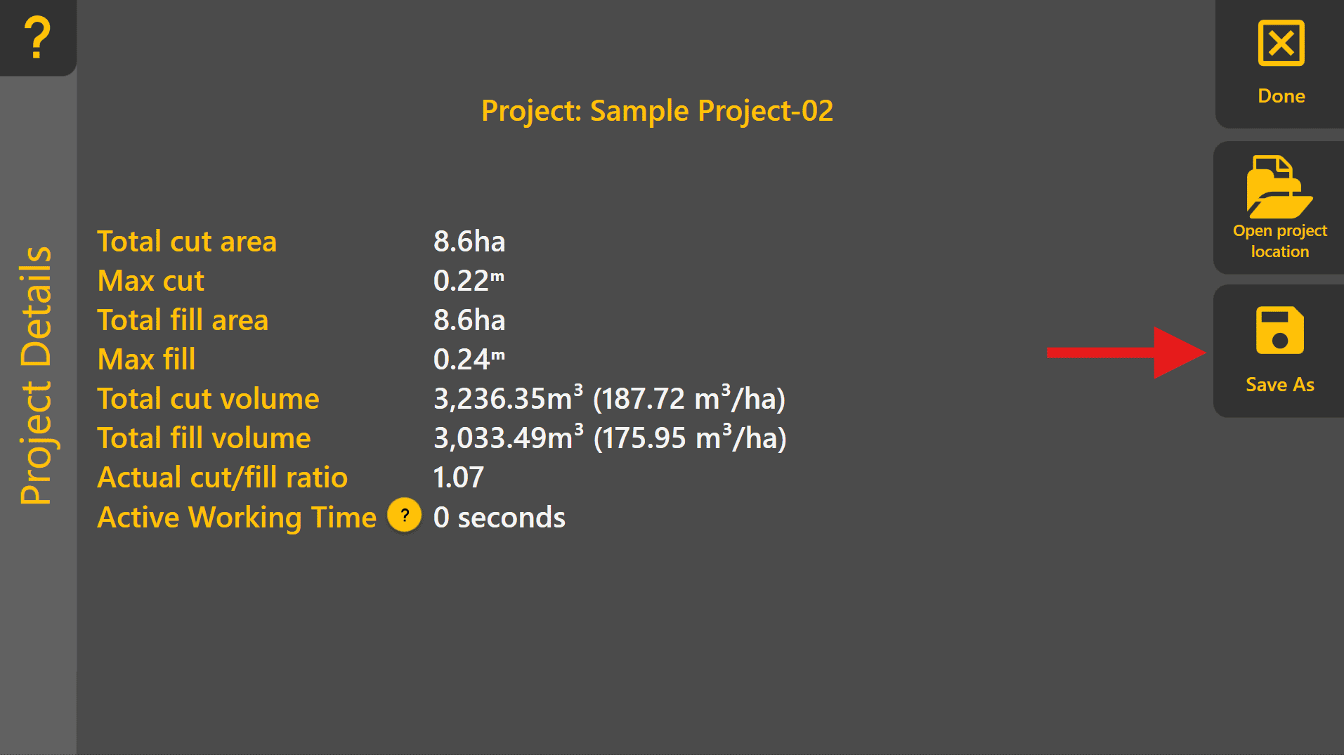
This can be useful when creating backups, archiving completed projects or creating a modified copy of an existing project.
Closing the Application
To close Level COMMAND:
-
Press More.
-
Press Close App at the bottom right.
-
Press Yes.
The application will close and return to the operating system.
Automatic Startup
Level COMMAND can be configured to start automatically when Windows starts.
To modify this setting:
More → Diagnostics/Advanced
Use the Start Level COMMAND when computer starts option to enable or disable automatic startup. This setting is enabled by default.

Unexpected Shutdowns
If the tablet or PC unexpectedly shuts down, COMMAND will automatically disengage Automatic Control once position updates are no longer received from Level COMMAND.
The operator immediately becomes responsible for machine control and implement position.
If an unexpected shutdown occurs:
-
Raise the implement if necessary.
-
Return hydraulic controls to a safe state.
-
Restart the tablet or PC.
-
Start Level COMMAND and verify system readiness before continuing work.
Because project information is saved automatically, work progress will normally be retained after restarting the application.
Restarting Level COMMAND
When Level COMMAND is started again:
-
The previous project remains available.
-
Previously created Plane surfaces and markers remain available.
-
Machine configuration and calibration settings remain stored within the COMMAND ECU.
Automatic Control will not automatically re-engage after restarting the application. The operator must verify system readiness and manually engage Automatic Control before continuing work.
Quick Start Complete
You have now completed the basic Level COMMAND Quick Start workflow:
-
Start Level COMMAND.
-
Check COMMAND Status.
-
Load or create a project.
-
Set Zero.
-
Engage Automatic Control.
-
Perform a pass.
-
Exit Level COMMAND safely.
For additional workflows, project creation tools and advanced operating procedures, continue to Chapter 5 | Operational Workflows.
5 | Operational Workflows
This chapter introduces the workflows used throughout normal grading operations. It explains how to create and manage projects, collect survey data, import designs, organise project markers and prepare work for Automatic Control.
5.1 | Apply View Overview
The Apply View is the primary operating screen used while grading. It combines machine guidance, design information, Automatic Control status and operator controls into a single workspace, allowing the operator to monitor grading progress and operate Level COMMAND without leaving the main screen.
Unlike the Quick Start chapter, which focuses on getting the machine operating, this section explains the purpose of each area of the Apply View and how they work together during normal operation.
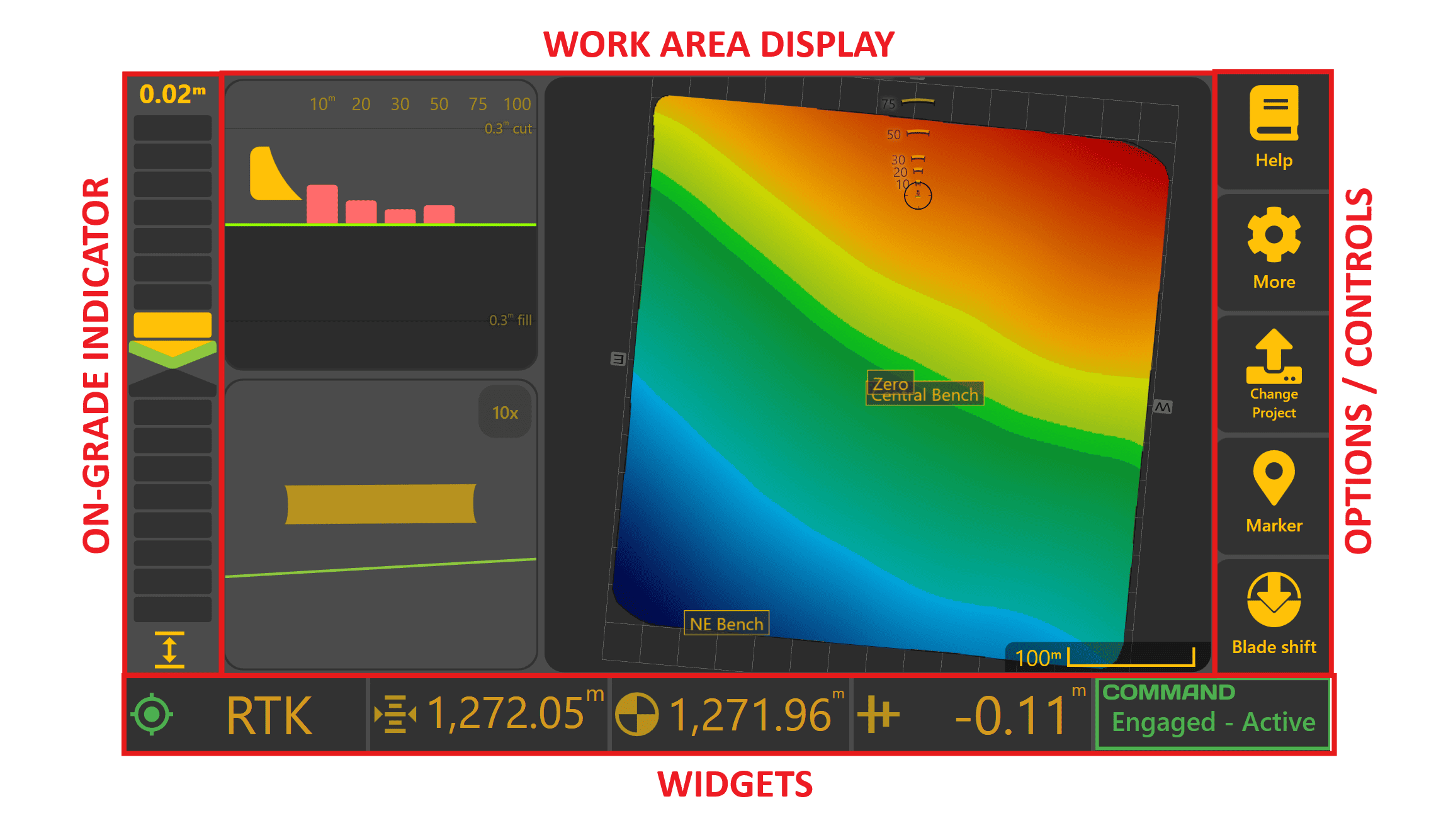
The Apply View can be divided into four main areas:
- On-Grade Indicator
- Work Area Display
- Operator Controls
- Status Widgets
Additional project information is available through the More menu when required.
On-Grade Indicator
 The On-Grade Indicator provides the quickest indication of whether the implement is currently above, below or on the target surface. During grading, it is typically the primary guidance reference used by the operator for monitoring height error.
The numerical value displayed above the indicator shows the current error between the implement position and the target surface.
- Arrow pointing up – the implement needs to be raised.
- Arrow pointing down – the implement needs to be lowered.
- Both arrows green with no coloured bars – the implement is within the configured deadband and is considered on grade.
As grading error increases, additional indicator segments illuminate to provide an immediate visual indication of how far the implement is from the target.
Deadband
A small deadband surrounds the target elevation to prevent the indicator continually changing state due to normal GNSS measurement variation.
By default, the deadband is ±1.5 cm. While within this range the indicator will appear on grade, although the numerical error value continues to display the true measured error.
 Blade Shift

Blade Shift temporarily offsets the current target above or below the design surface without changing the design itself.
When Blade Shift is active, a Blade Shift icon is displayed beneath the indicator. This reminds the operator that the current target has been intentionally offset from the design surface.
 Cut/Fill Limiting

When Dynamic Cut or Fill Limiting is enabled, the indicator normally displays the error between the implement and the limited target rather than the final design surface.
Pressing/tapping the indicator toggles between:
- Current tracking target (limited).
- Error to the final design surface.
When displaying error to the design surface, the indicator uses the current cut/fill colour scheme to show the full design error.
Work Area Display
The centre of the Apply View displays the current work area together with optional guidance views that assist the operator while grading.
The display consists of one primary viewing area and two secondary viewing areas. Each area can independently display:
- Map
- Side View
- Back View
Operators can arrange these views to suit different tasks using the Layout settings.
Examples include:
- Full-screen Map
- Map + Side View
- Map + Back View
- Side View + Back View
- Map + Side View + Back View
The purpose of each view is described below.
Map
 The Map displays the current project together with the machine position.
During operation it is primarily used to:
- Monitor grading progress
- Identify remaining cut and fill
- Plan efficient travel paths
- Review completed work
Selecting any point on the map displays information for that location, including surface values where available.
The displayed colours and surface layers are configurable using the Appearance settings described later in this chapter.
Side View
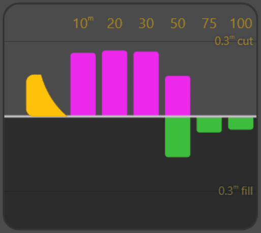 The Side View provides a preview of the terrain ahead of the implement based on the current direction of travel. Upcoming cuts and fills are displayed relative to the design surface, allowing the operator to anticipate changing ground conditions before reaching them.
As grading progresses, the preview updates using the current As Applied Cut/Fill surface, allowing the operator to see grading progress in front of the machine.
Back View
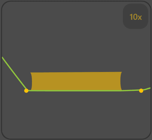
The Back View displays a cross-section across the blade width.
This view is particularly useful when grading dual-height and Height + X-Slope applications, allowing the operator to compare the measured surface against the design across the entire implement width.
The displayed vertical scale can be adjusted by selecting the scale indicator.
Where project linework intersects the displayed cross-section, intersection markers are also shown to assist with alignment.
Operator Controls
The right-hand toolbar provides quick access to the functions most commonly used while grading.
Depending on the current project type, some buttons may change to provide direct access to project-specific functions such as Plane selection or Project selection.
Detailed operation of these functions is covered throughout this manual.
The primary controls include:
| Control | Purpose |
|---|---|
| Help | Opens the Level COMMAND manual. |
| More | Accesses additional settings, diagnostics and project functions. |
| Project / Plane | Changes projects or manages Plane surfaces depending on the current project type. |
| Marker | Creates project markers and benchmarks. |
| Blade Shift | Temporarily offsets the target above or below the design surface without modifying the design itself. |
Status Widgets
The widgets along the bottom of the Apply View display continuously updated operating information while grading.
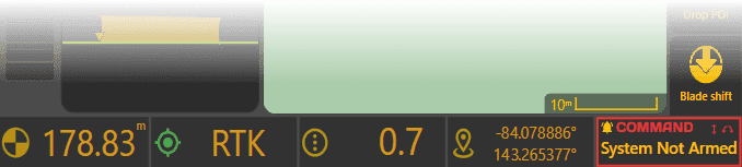
Widgets can display a wide variety of operating information, including:
- GNSS status
- Speed
- Elevation
- Current Error
- Hydraulic information
- Position
- Cut/Fill values
The COMMAND Status widget is always displayed at the bottom-right of the Apply View and cannot be removed. It continuously reports the current operating state of the COMMAND ECU, including readiness, engagement state and any operator actions or faults requiring attention.
Widget selection and layout are fully configurable and are described in 5.3 | Widget Customisation.
Operator Tip: Becoming familiar with the Apply View allows you to monitor machine performance, anticipate changes in terrain and access the controls required for efficient grading without leaving the main operating screen.
Once you are familiar with the Apply View, continue to 5.2 | Apply View Layout, which explains how the display can be customised to suit different operating preferences and grading tasks.
5.2 | Apply View Layout
The Layout page allows the Apply View to be customised to suit different machines, grading tasks and operator preferences.
To open the Layout page from the Apply View, press:
More → Layout
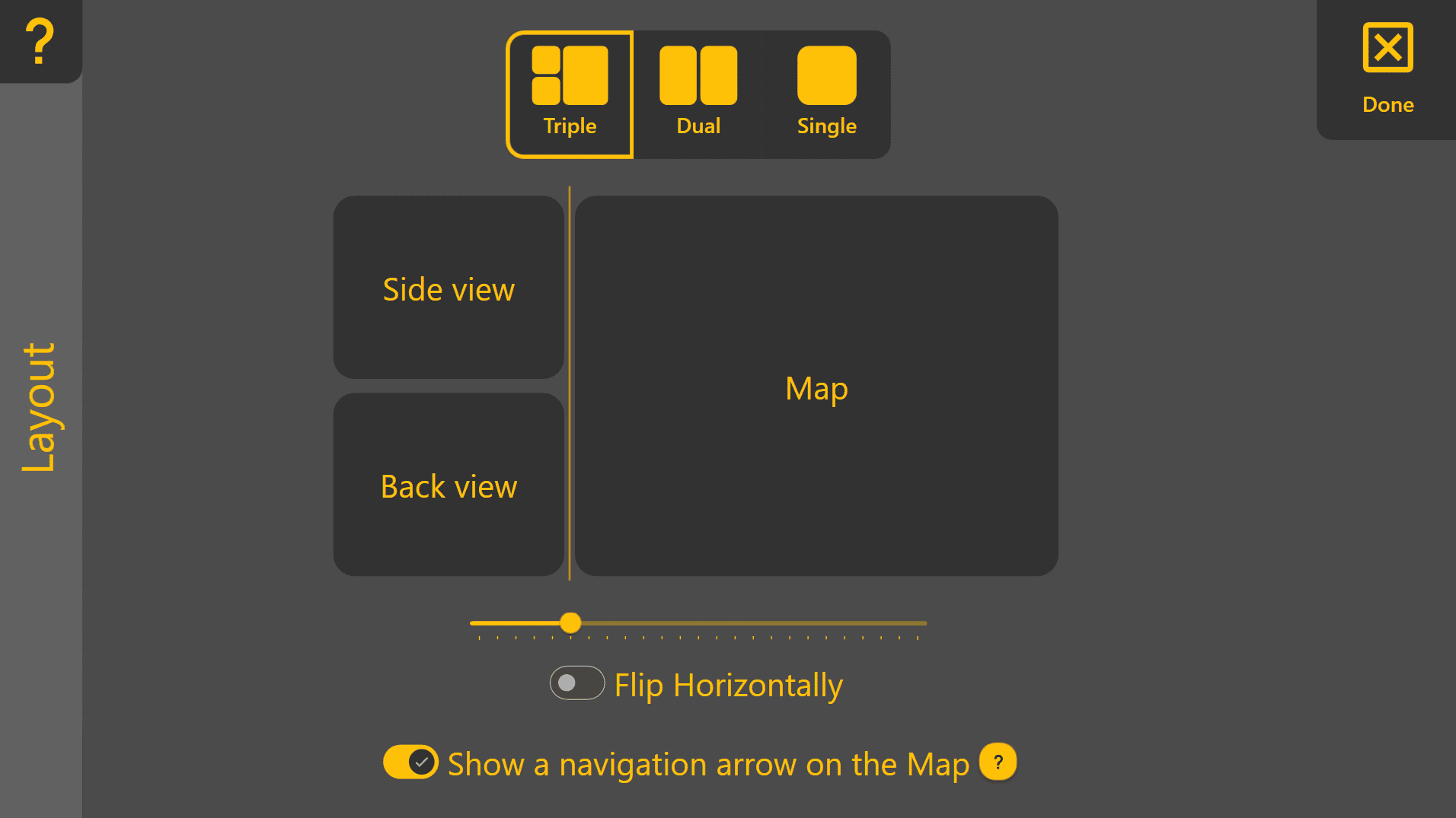
Choosing a Layout

Three layout modes are available:
- Triple – Displays one main viewing area with two secondary viewing areas.
- Dual – Displays one main viewing area with one secondary viewing area.
- Single – Displays a single view across the entire screen.
Select the desired layout by pressing Triple, Dual or Single at the top of the page.
Selecting Display Views
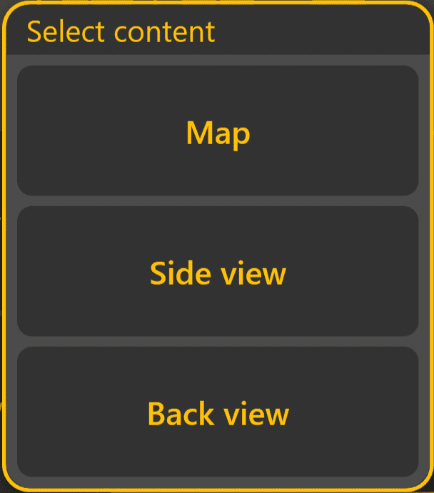
Each display area can independently display one of the following:
- Map
- Side View
- Back View
Simply press any display area shown on the Layout page to choose which view it will display.
This allows the Apply View to be configured for different operating tasks. Common examples include:
- Full-screen Map for maximum work area visibility.
- Map + Side View to preview upcoming cut and fill.
- Map + Back View to monitor cross-fall.
- Map + Side View + Back View to view all guidance information simultaneously.
Layout Options
Additional options are available when using the Dual or Triple layouts.
Split Position
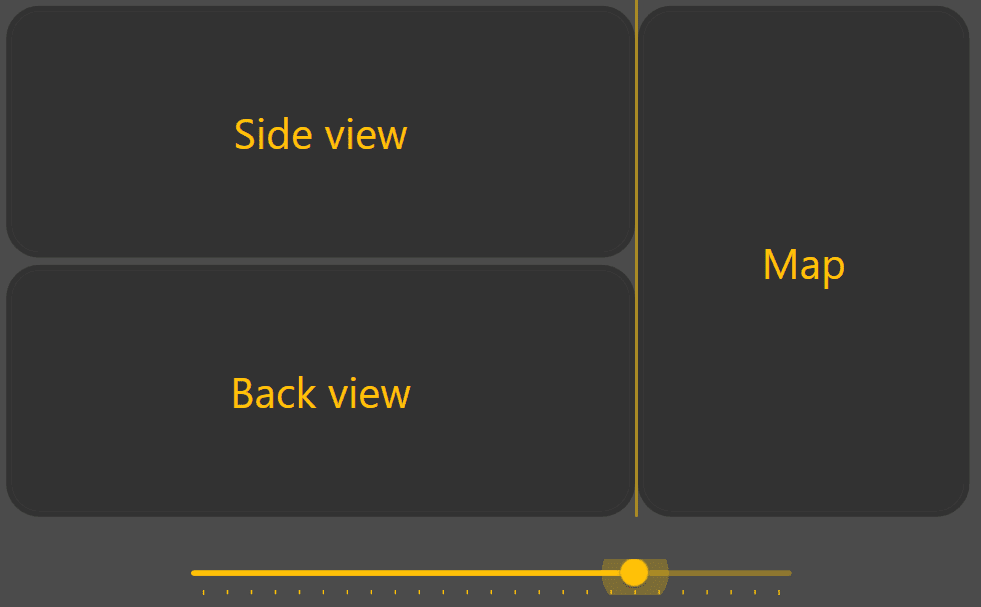 Use the slider to adjust how much screen space is allocated to the main viewing area and the secondary viewing areas.
Increasing the size of the main viewing area provides a larger Map display, while increasing the secondary viewing areas makes the Side View or Back View easier to monitor.
Flip Horizontally
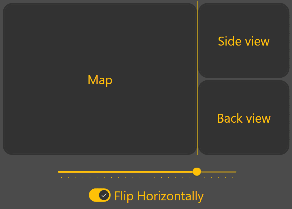
Enable Flip Horizontally to swap the positions of the main and secondary viewing areas.
This can improve visibility depending on display mounting position or operator preference.
Navigation Arrow

The arrow points towards the centre of the project surface and displays the approximate direction and distance to the work area. This can be particularly useful when travelling between fields or locating a project after loading it.
Continue to 5.3 | Widget Customisation to configure the information displayed along the bottom of the Apply View.
5.3 | Widget Customisation
The widgets along the bottom of the Apply View provide quick access to important machine, GNSS and grading information while operating Level COMMAND.
Almost every widget can be replaced with another value, allowing the display to be customised to suit different operators, machine configurations or grading tasks.
The COMMAND Status widget at the far right of the Apply View is fixed and cannot be changed.
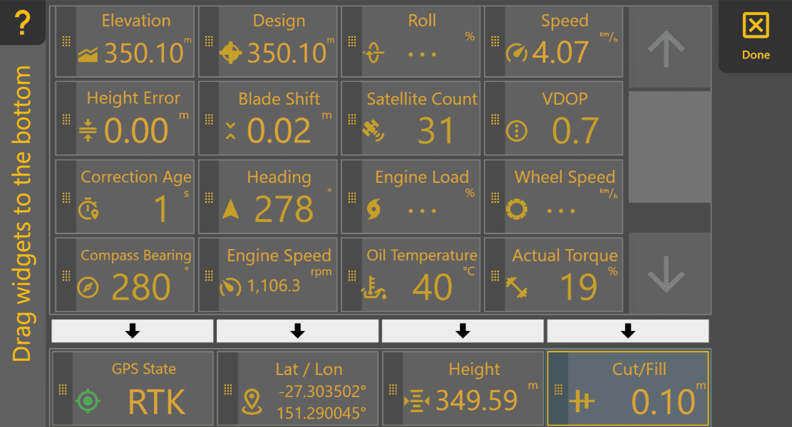
Opening Widget Settings
To customise the displayed widgets:
- Press and hold any configurable widget along the bottom of the Apply View.
- The Widget Settings page will open.
The upper section displays all available widgets, while the lower section shows the widgets currently displayed on the Apply View.
Changing Displayed Widgets
Widgets can be replaced using either of the following methods.
Drag and Drop
Press and hold any available widget, then drag it onto one of the widget positions along the bottom of the screen. When released, the selected widget replaces the existing widget.
Arrow Selection
Alternatively:
- Select the desired widget from the upper list.
- Press the arrow above the widget position you wish to replace.
This method can be easier when operating with gloves or on smaller displays.
Reordering Widgets
Widgets may also be rearranged by dragging them between positions along the bottom row.
When finished, press Done to return to the Apply View.
Changing Measurement Units
Many widgets display measurements using configurable units.
To change measurement units:
More → Units
The available units depend on the information being displayed.
Available Widgets
| Widget | Description |
|---|---|
| Elevation | Current surveyed ground elevation at the implement location. |
| Design | Design elevation at the current location. |
| Height | Current implement height. |
| Cut/Fill | Amount of cut or fill required at the current location. |
| Height Error | Difference between the current implement height and the target height. Persistent error may indicate incorrect valve calibration or that the implement cannot physically reach the target. |
| Blade Shift | Displays the current Blade Shift offset applied to the target surface. This widget displays the active offset only; Blade Shift is adjusted using the Blade Shift control on the Apply View. |
| Speed | Current machine speed. |
| Heading | Current direction of travel relative to north. |
| Latitude / Longitude | Current GNSS position. |
| Roll (X-Slope) | Current implement roll angle. |
| Target Roll | Target roll angle defined by the design surface. |
| Roll Error | Difference between the measured roll angle and the target roll angle. Useful when monitoring X-Slope performance. |
| GNSS Status | Current GNSS positioning quality. RTK provides the highest positioning accuracy. |
| Satellite Count | Number of satellites currently being tracked. Some receivers may report fewer satellites than are actually contributing to the position solution. |
| VDOP | Vertical Dilution of Precision. Lower values generally indicate better vertical positioning accuracy. |
| Correction Age | Time since the last RTK correction was received. Lower values indicate a healthier correction link. |
| Actual Torque* | Engine torque currently being produced. |
| Demanded Torque* | Engine torque currently being requested. |
| Engine Load* | Current engine load as a percentage. |
| Engine Speed* | Current engine speed (RPM). |
| Oil Temperature* | Hydraulic oil temperature. |
| Compass Bearing* | Vehicle heading reported by the machine. |
| Wheel Slip* | Estimated wheel slip percentage. Higher values indicate reduced traction. |
*Available only when supported by the connected machine CAN network.
Operator Tip: Configure the widgets you check most often so they can be read with a quick glance while grading. Some operators keep GNSS Status, Height, Cut/Fill and Current Blade Shift permanently visible, then customise the remaining widget to suit the current task.
Continue to 5.4 | Surface & Map Visualisation to configure the appearance of the Work Area Display within the Apply View.
5.4 | Plane Projects & Surface Creation
Plane Projects allow simple design surfaces to be created without first surveying the entire work area. They are commonly used for creating flat pads, graded surfaces, drain batters and other simple earthworks. Each Plane Project can contain up to four individual Plane surfaces, making it easy to switch between different work areas or design surfaces without creating additional projects.
Creating a Plane Project
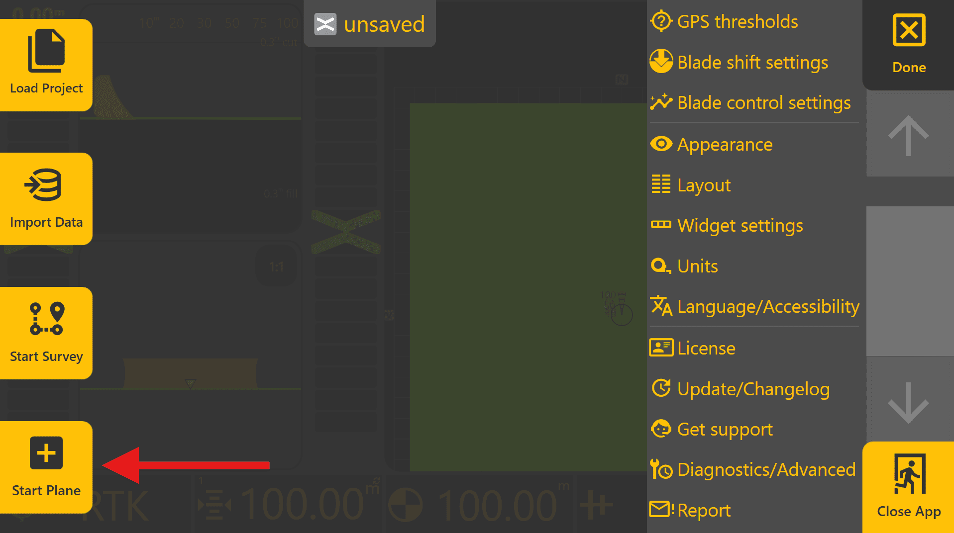
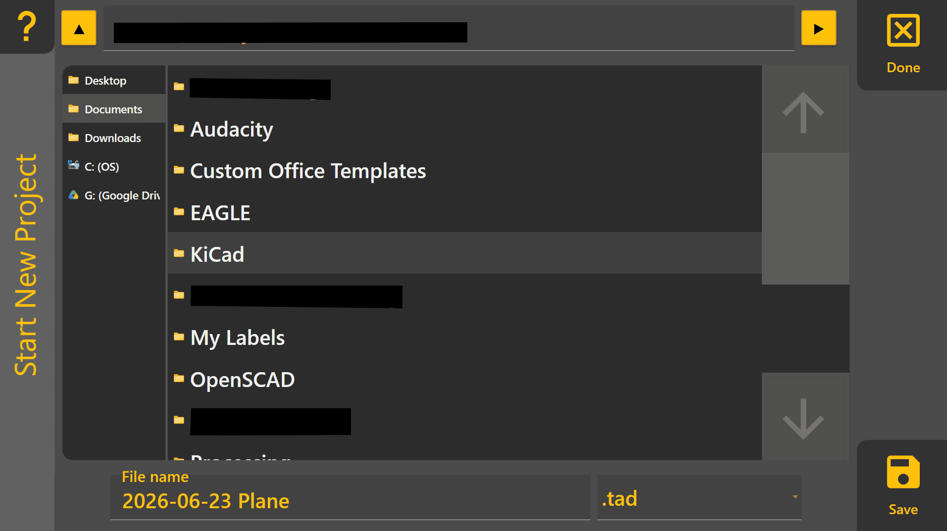
Selecting and Managing Plane Surfaces

Press Planes on the right side of the Apply View to display the available Plane slots.
Up to four Plane surfaces can be stored within a single Plane Project. Each Plane can have its own:
- Name
- Size
- Origin Point
- Primary Slope
- Secondary Slope
- Elevation Offset
To create a new Plane, select any unused slot labelled Create and the Plane Editor will open on the right side of the screen.
To switch between existing Planes, select the desired Plane from the list. The active Plane is indicated by a yellow outline.
To edit an existing Plane, select it and then select it again to open the Plane Editor. The Plane Editor is used to define and modify all Plane properties, including origin, slopes and survey-based Plane generation.
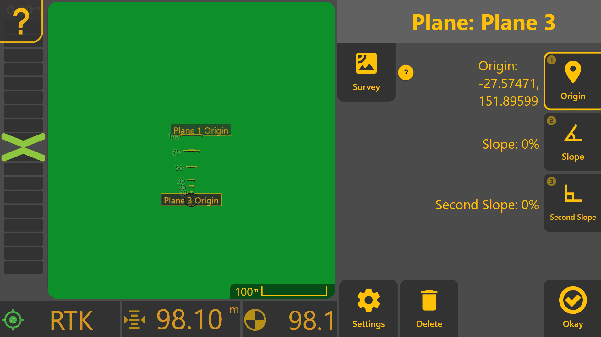
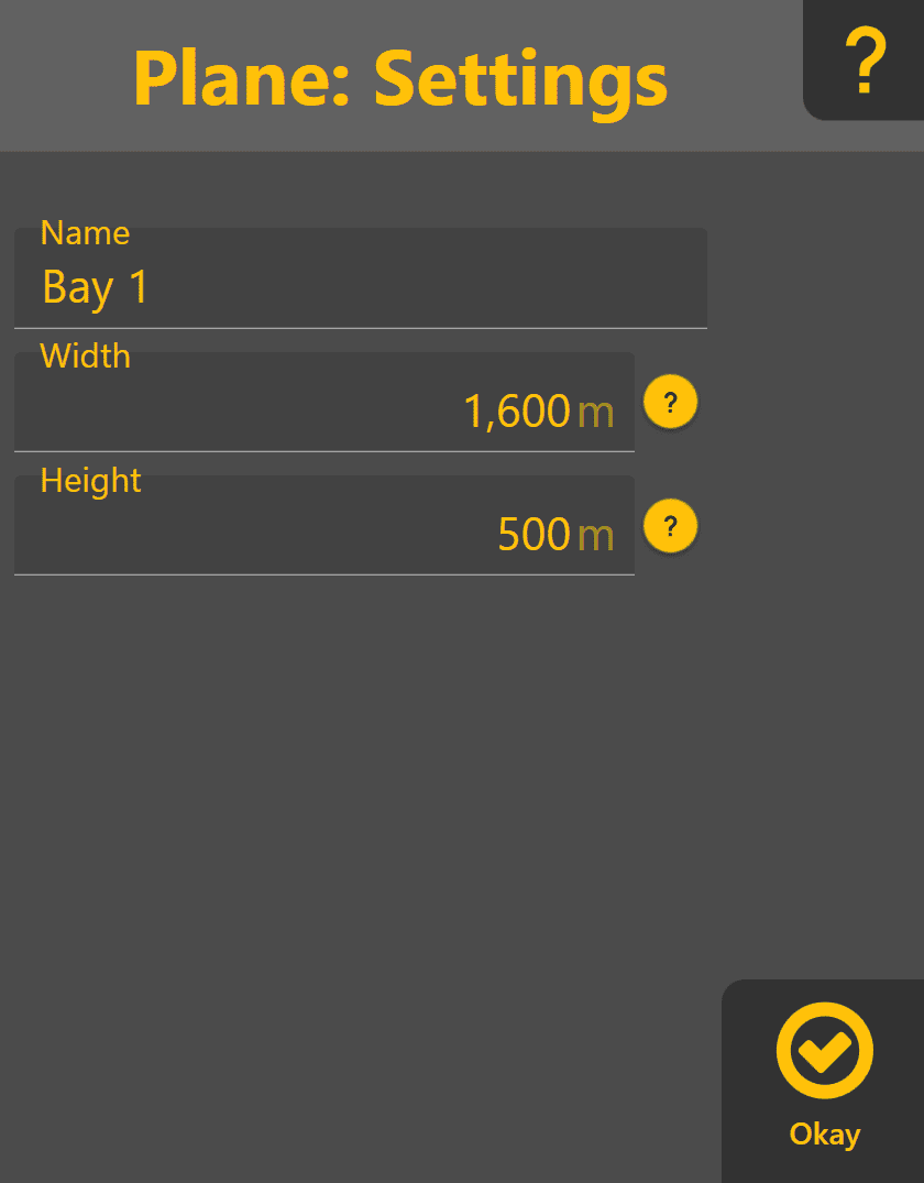
Plane Settings
Press Settings within the Plane Editor to configure the Plane name and dimensions. Assigning a meaningful Name makes it easier to identify different work areas within a project.
Plane Width and Height determine the visible extent of the generated Plane surface. These values may be adjusted at any time without affecting the calculated grade of the Plane.
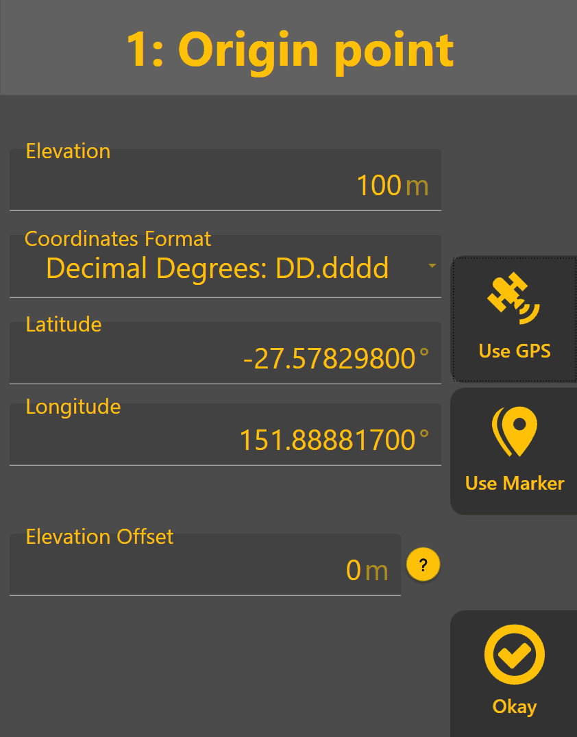
Defining the Origin Point
The Origin Point is the reference position used to define the Plane elevation and calculate all Plane slopes. It can be thought of as the anchor point of the Plane.
Press Origin within the Plane Editor to define or modify the Origin Point.
The Origin may be defined using:
- Use GPS – Sets the Origin to the current implement position and elevation.
- Use Marker – Uses an existing marker as the Origin Point.
- Manual Coordinates – Allows Latitude, Longitude and Elevation values to be entered directly.
Manual coordinate entry is commonly used when creating a Plane from a surveyed benchmark or known control point.
Once the Origin has been defined, press Okay to return to the Plane Editor. A newly created Plane will initially be flat, with the Origin positioned at the centre of the surface.
Elevation Offset
Elevation Offset allows the entire Plane to be shifted vertically without changing the underlying Plane definition. This is commonly used to quickly raise or lower a design surface when filling, trimming or removing surface irregularities while preserving the existing Plane slopes.
Positive values raise the Plane. Negative values lower the Plane.
Coordinate Formats
The Coordinate Format setting changes how Latitude and Longitude values are displayed. This is a display preference only and does not affect the actual position of the Plane.
Defining the Primary Slope
The Primary Slope defines the main grade direction of the Plane and determines how the surface rises or falls across the work area. Press Slope within the Plane Editor to define the Primary Slope.
The Primary Slope may be created automatically by using a second point on the desired grade surface:
-
Position the machine at the desired second point on the Plane.
-
Place the blade on the ground or at the desired design elevation.
-
Press Use GPS.
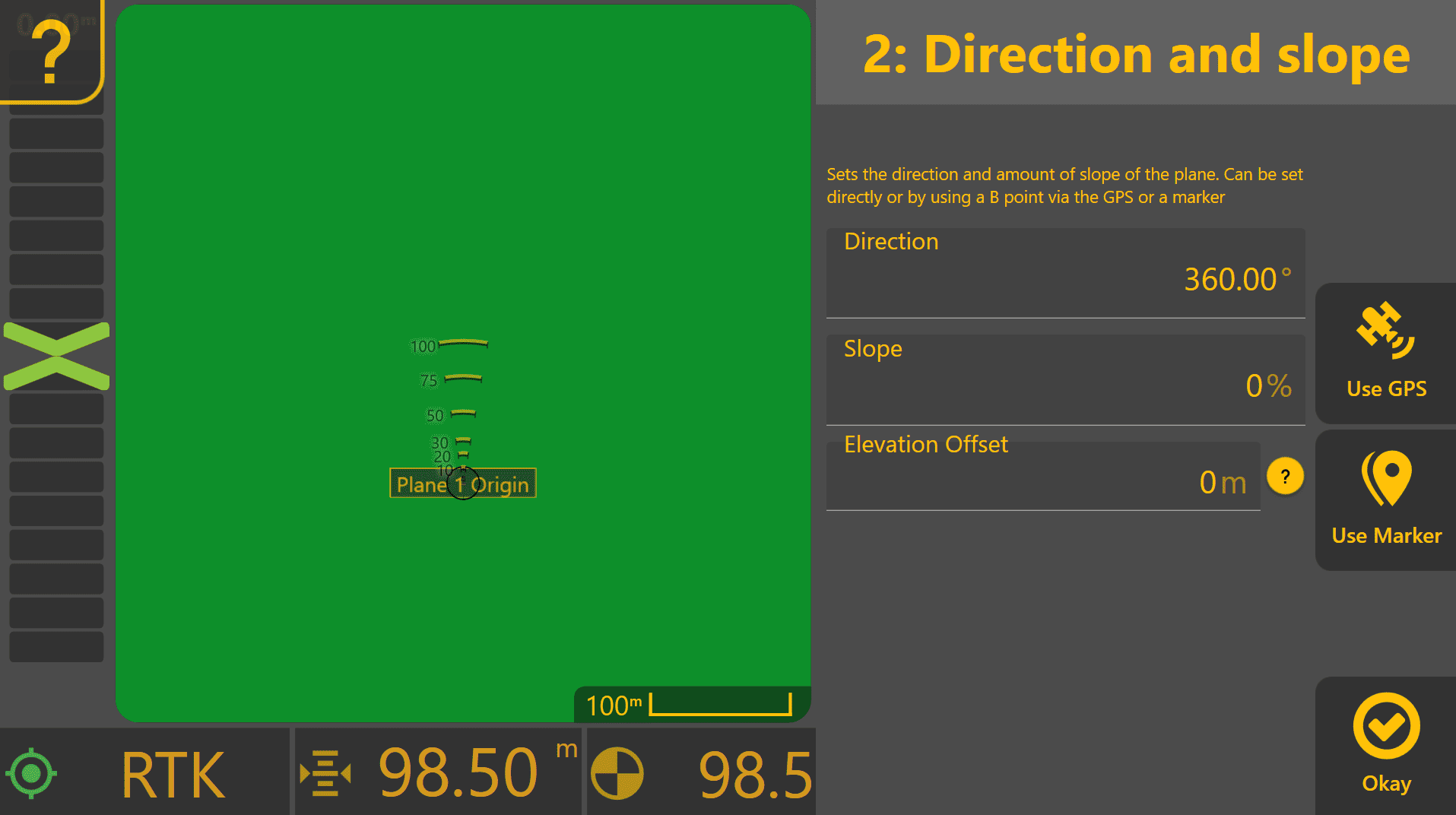
Level COMMAND will calculate the slope and direction between the Origin Point and the selected location, then update the Plane surface automatically. Alternatively, the slope percentage and direction may be entered manually if the desired grade is already known.
Once the desired slope has been defined, press Okay to return to the Plane Editor.
Direction
Direction determines the heading along which the Primary Slope is applied.
Slope
Slope determines how steeply the Plane rises or falls along the selected direction. Slope values are expressed as a percentage:
Slope (%) = 100 × Rise ÷ Run
Use GPS
Calculates the slope and direction automatically using the current implement position and the Origin Point. The calculated values may be edited afterwards if required.
Use Marker
Calculates the slope and direction using a previously created Marker and the Origin Point. The calculated values may be edited afterwards if required.
Defining the Secondary Slope
The Second Slope (X-Slope) defines the cross-fall of the Plane at right angles to the Primary Slope. This is commonly used when creating crowned surfaces, side-falls, drain batters or other surfaces requiring grade in two directions.
Press Second Slope within the Plane Editor to define the Secondary Slope. As with the Primary Slope, the Secondary Slope can be generated automatically using a second reference point:
-
Position the machine at a point representing the desired cross-fall of the Plane.
-
Place the blade on the ground or at the desired design elevation.
-
Press Use GPS.
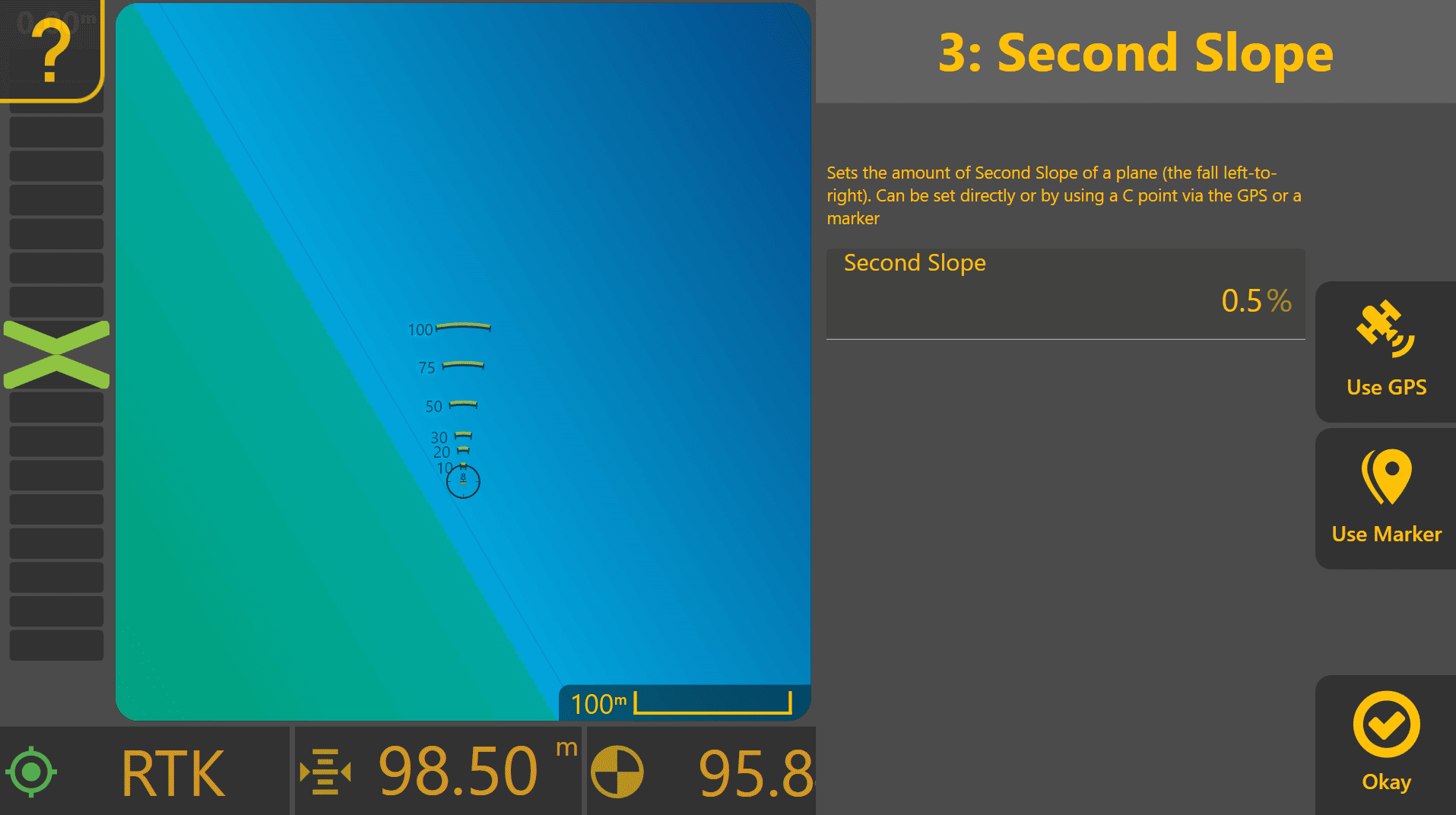
Level COMMAND will calculate the Secondary Slope relative to the Origin Point and update the Plane surface automatically. Alternatively, a known Secondary Slope percentage may be entered manually.
Unlike the Primary Slope, direction does not need to be specified because the Secondary Slope is always applied at 90 degrees to the Primary Slope.
Once the desired Secondary Slope has been defined, press Okay to return to the Plane Editor.
The final Plane surface is calculated using the Origin Point, Primary Slope and Secondary Slope together to define the overall grade of the design surface.
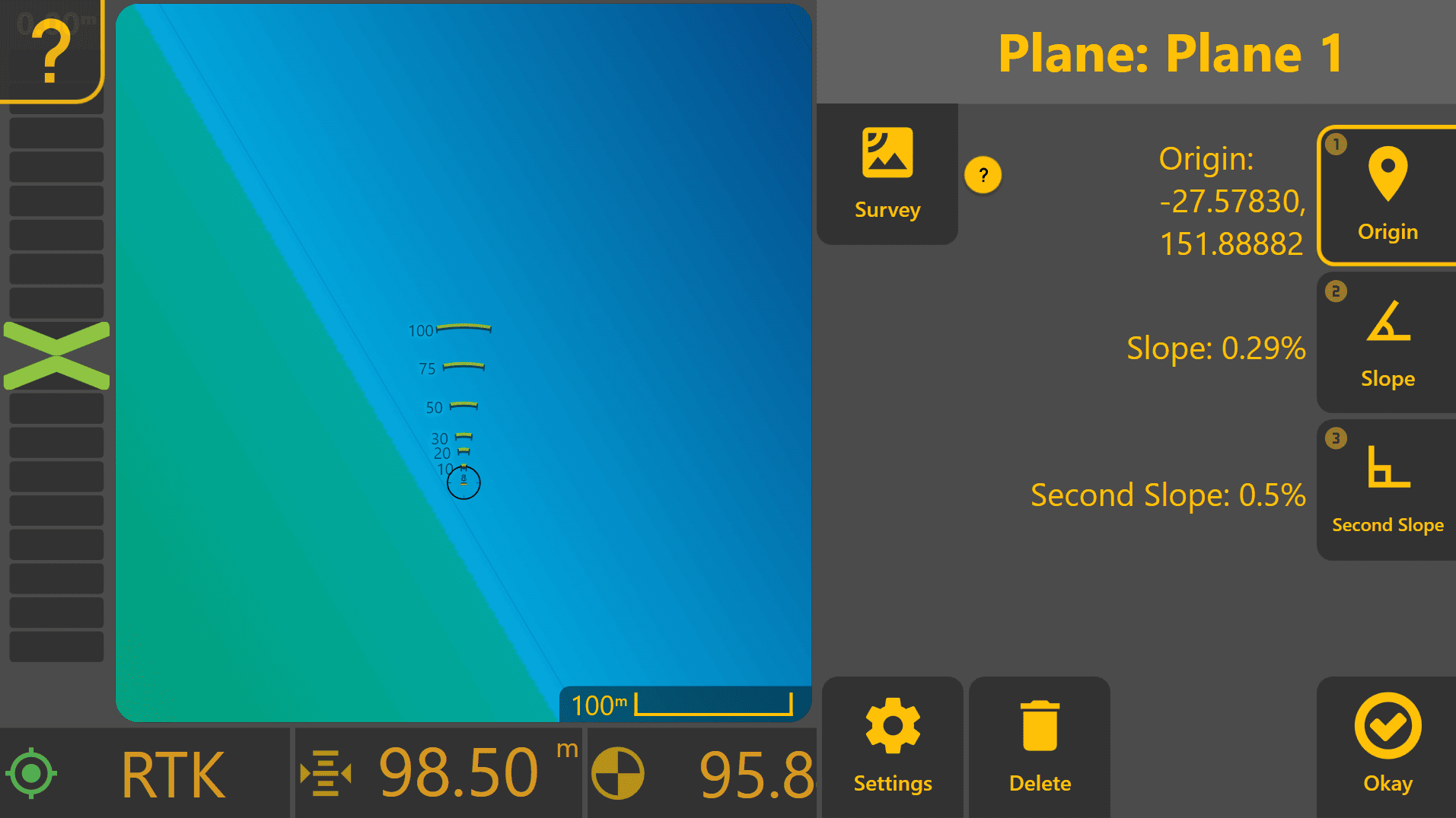
Surveying & Generating A Best Fit Plane
 When the desired Plane slope and direction are not known, Level COMMAND can survey an area and automatically generate a best-fit Plane surface.
A best-fit Plane represents the average grade of the surveyed area by calculating the most suitable Plane from the collected survey positions and elevations.
This workflow is commonly used when:
- Levelling an existing paddock while maintaining the current fall.
- Smoothing high and low spots without significantly changing overall drainage.
- Creating a Plane surface when the desired grade has not been surveyed or designed beforehand.
- Quickly generating a reference surface for testing and machine setup.
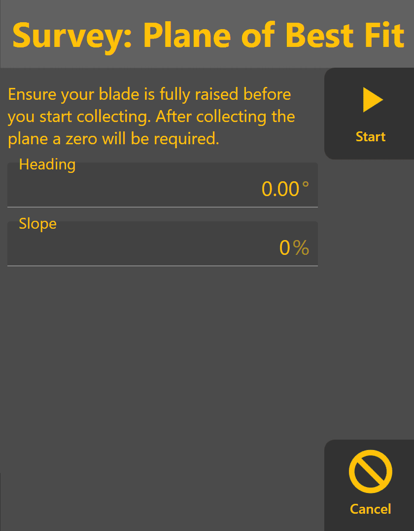
Creating a Best-Fit Plane
- Press Planes from the Apply View.
- Select an available Plane slot.
- Press Survey.
- Press Start to begin recording survey points.
- Drive throughout the area to be represented by the Plane surface.
- Press Stop once the survey is complete.
Level COMMAND will analyse the collected survey points and automatically calculate a best-fit Plane.
Once generated, the calculated Plane will be displayed and can immediately be used for Automatic Control.
Surveying Tips
For best results:
- Survey the entire area that will be worked.
- Collect points from both high and low areas.
- Avoid surveying only a small section of the work area.
- Raise the implement while surveying to avoid unintended grading. Once surveying has started, maintain a consistent implement height and avoid making manual height adjustments until the survey is complete.
As additional survey points are collected, the calculated Plane heading and slopes will generally become more stable and representative of the surveyed area.
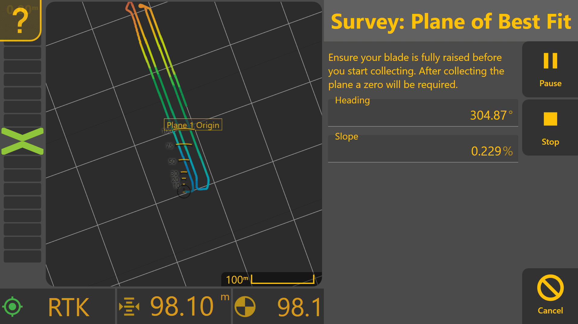
Reviewing the Calculated Plane
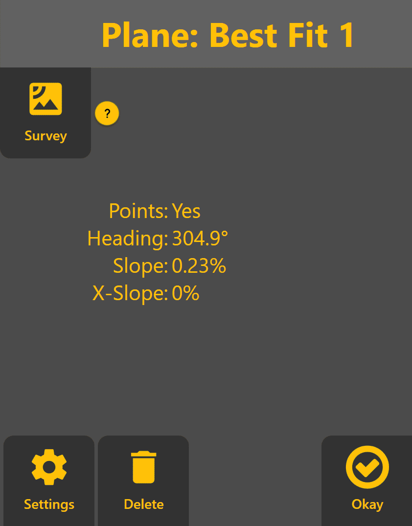 Once the Plane has been generated, selecting the Plane from the Planes menu will display the calculated:
- Heading
- Primary Slope
- Secondary Slope (X-Slope)
These values may be entered into a new plane if adjustment is required.
Additional Controls
The following controls remain available while working with a surveyed Plane:
- Settings – Modify the Plane name and dimensions.
- Delete – Remove the Plane and free the slot for reuse.
- Survey – Perform a new survey and recalculate the Plane.
- Okay – Save the Plane and return to the Apply View.
5.5 | Pre-designed Projects & Data
Pre-designed Projects allow Level COMMAND to grade using surfaces that have been created outside the application. These projects are typically prepared by a dealer, surveyor or designer before being transferred to the machine.
Compared with Plane Projects, imported projects can contain significantly more information, including surveyed terrain, finished design surfaces, boundaries, linework, markers and benchmark locations.
Preparing Design Data
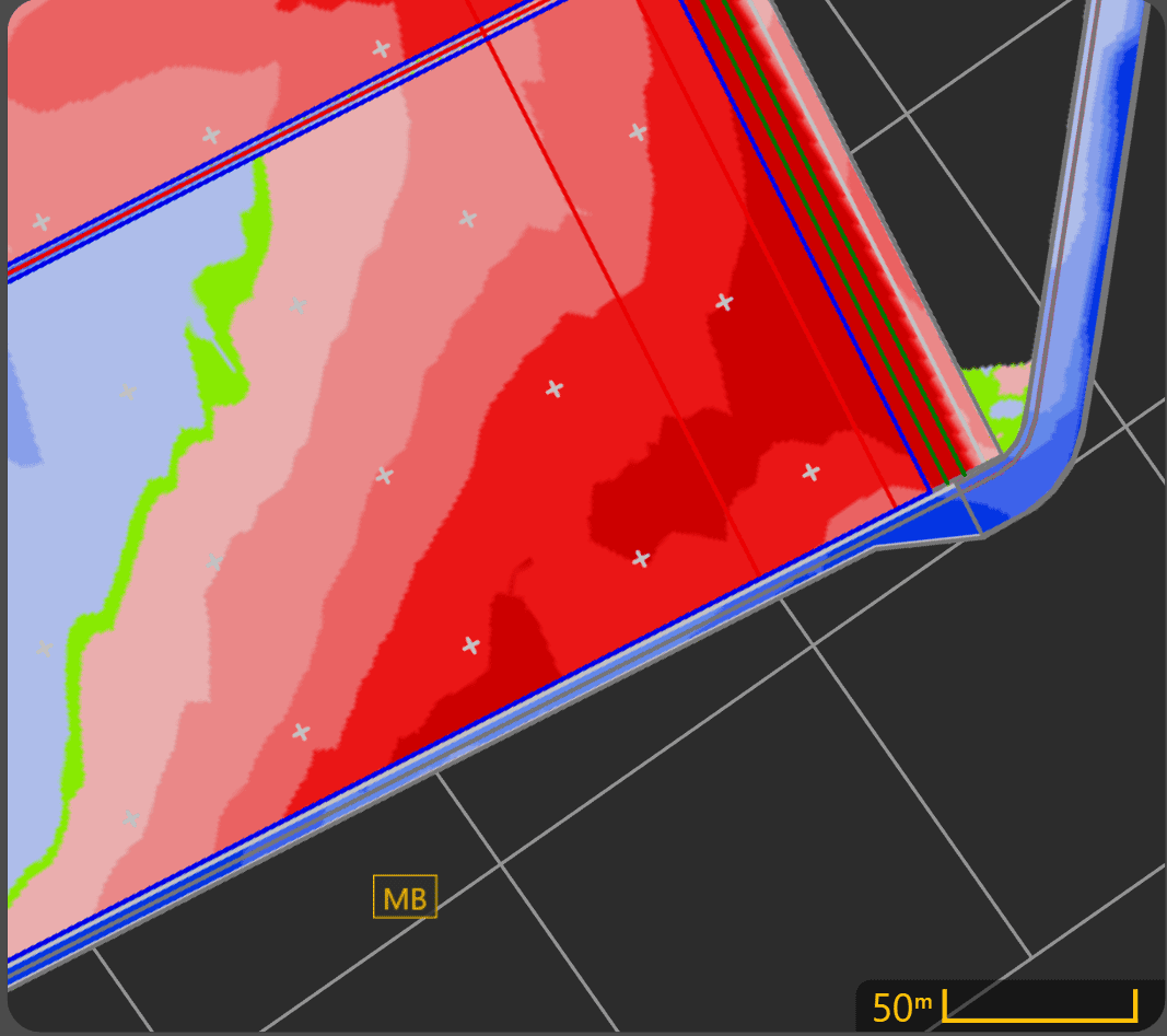 Before importing a project, verify that the supplied design includes the information required for the intended grading operation.
Where possible, imported projects should include:
- A finished design surface.
- One or more Benchmark Markers for zeroing.
- Boundaries where appropriate.
- Linework or other design features if required.
Benchmarks should be placed in locations that:
- Can be reached safely by the machine.
- Are unlikely to be disturbed during construction.
- Provide sufficient room to accurately position the implement during zeroing.
Following these practices makes future verification and re-zeroing significantly easier.
Supported File Types
At the time of writing, Level COMMAND supports importing T3RRA project files:
| File Type | Description |
|---|---|
| .tci | T3RRA project file containing one or more design surfaces and associated project data. |
Additional import formats may be supported in future software releases.
 Loading an Existing Level COMMAND Project
To load an existing Level COMMAND project:
- Press More → Load Project.
- Select the desired project.
- Press Load.
The selected project immediately becomes the active grading project.
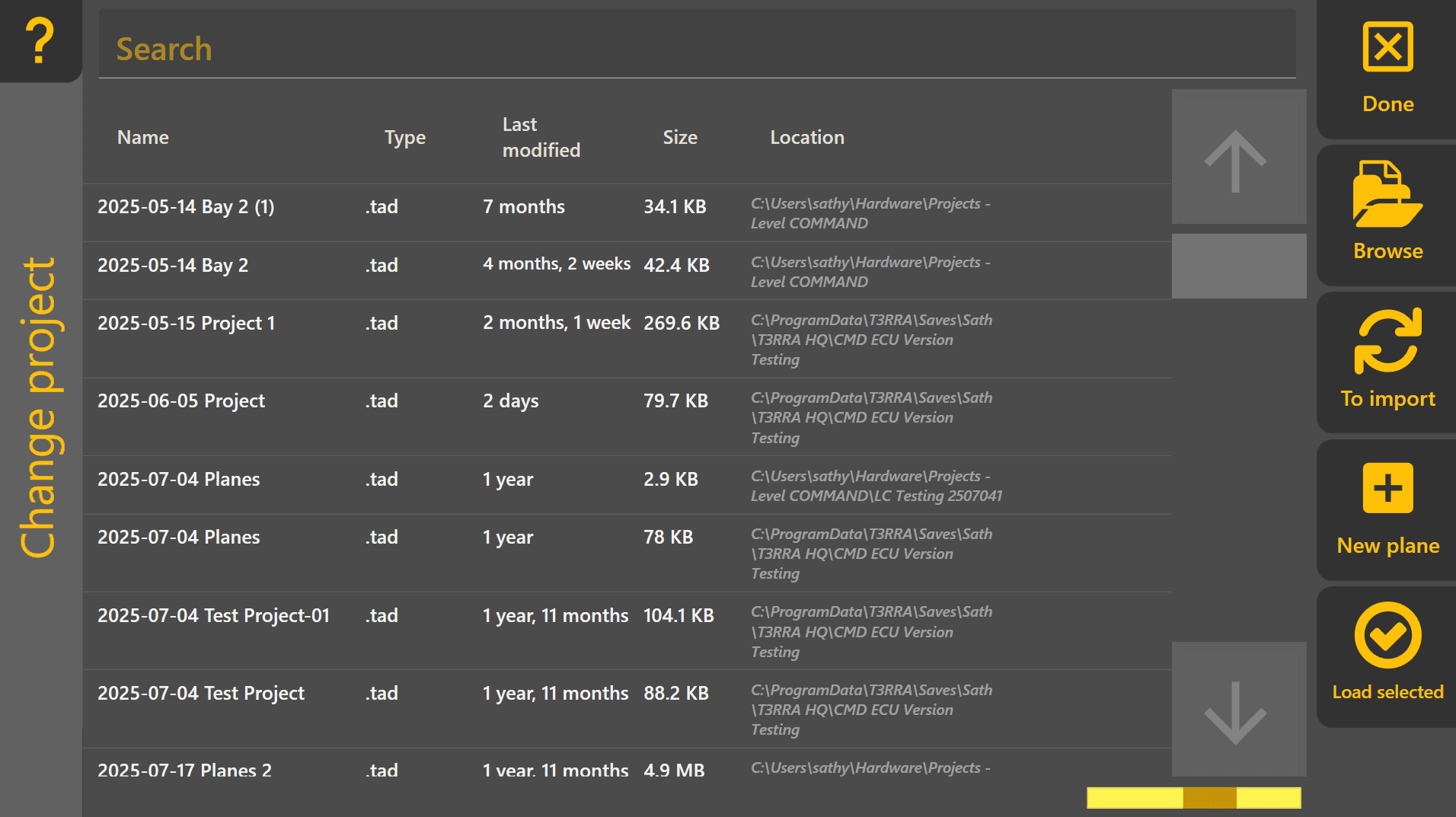
Importing External Design Data
To import new design data into Level COMMAND:
- Press More → Import Data.
- Select the desired design file.
- Press Import Selected.
- Once complete, load the imported project if it does not open automatically.

Imported data becomes part of a Level COMMAND .tad project and can then be used like any other project.
Imported Project Features
Depending on how the project was created, imported data may include:
- Design surfaces
- Existing terrain surveys
- Benchmark Markers
- General Markers
- Boundaries
- Linework
- Additional project information
The available information depends on the design software used and the data exported.
Working with Imported Projects
Once loaded, imported projects are operated in the same way as any other project.
The operator may:
- Set Zero using a Benchmark Marker.
- Record additional surveys.
- Create new markers.
- Monitor cut and fill.
- Engage Automatic Control.
- Continue updating surveyed surfaces during grading.
Although imported projects may contain complex design information, the grading workflow remains exactly the same as described throughout this manual.
Operator Tip: If possible, review imported project data before arriving on site. Confirm that the expected design surface, benchmark locations and project features are present before beginning work. Discovering missing benchmarks or incorrect project data is far easier before the machine enters the field.
Continue to 5.6 | Surveying & Field Data Collection to learn how Level COMMAND records terrain data for design creation, project verification and future grading operations.
5.6 | Surveying & Field Data Collection
The Survey tool records GNSS-referenced terrain and feature data for design creation, project verification, and archival purposes. Collect a survey before grading to capture existing ground, or after grading to verify completed work. Survey data can be exported in T3RRA project format or FieldLevel XML for compatible design software.
Starting a Survey
Before recording, confirm that the GNSS receivers have an RTK fix. Survey accuracy depends on GNSS positioning quality. Raise the blade to full height when prompted.
- Press More → Start Survey.
- Select where the survey project will be saved.
- Press Save.
- In the Survey window, press Start Survey to open the survey-type selector.
- Choose Boundary, Drains/Paths, or Full Field. You can also collect a benchmark from the survey controls.
A new blank survey project is created and displayed in the Work Area. The first Start Survey button opens the selector; after a type is chosen, the same button starts or resumes recording.
Survey Types
Select the type of feature to collect before recording begins.
Boundary
Records the perimeter of a field or work area. Drive around the complete perimeter and collect enough points to represent the boundary accurately.
Drains / Paths
Records a linear feature such as a drain, channel, road, or access track. Follow the feature from one end to the other. When the survey is stopped, Level COMMAND prompts for a drain name.
Full Field
Records terrain data across the work area. Drive a consistent pattern with adequate overlap between passes to reduce gaps in the collected data.
Recording Survey Data
- After choosing a survey type, press Start Survey to begin recording.
- Drive through the area while maintaining RTK positioning and following the route for the selected survey type.
- Press Pause to temporarily suspend recording.
- Press Start Survey again to resume after pausing.
- Press Stop when the current survey is complete.
If you decide to discard the current collection before completing it, press Cancel in the survey-type selector and begin again. Use Pause when you intend to continue the current collection.
After stopping, press Start Survey again to collect another Boundary, Drains/Paths, or Full Field survey.
Recording Markers
Markers can be recorded while surveying to identify important locations such as gateways, fence corners, irrigation equipment, hazards, or drain inlets and outlets. For the full distinction between general markers and benchmark markers, see 5.7 | Markers & Benchmarks.
Exporting Survey Data
Stop surveying before exporting. Press Export, select the format and destination, then press Export again.
| Format | Purpose |
|---|---|
| .tci | Native T3RRA project format. |
| FieldLevel XML | Export for compatible third-party design software. |
Exporting requires the appropriate product permission. If the export option is unavailable or permission is denied, contact your administrator or T3RRA support.
Operator Tip: Survey quality directly affects design quality. Obtain RTK before recording, keep a consistent speed, cover the complete area, and use adequate overlap between passes. If a section is missed or GNSS quality is poor, collect that section again before exporting.
5.7 | Markers & Benchmarks
Level COMMAND allows important locations within a project to be recorded using Markers and Benchmarks. Although both are created using the same tool, they serve different purposes during surveying, grading and future site visits.
Markers provide useful reference points for operators and designers, while Benchmarks provide permanent reference locations used for project alignment and zeroing.
Marker Types
Two marker types are available:
General Markers
General Markers record locations or features of interest within a project. They are commonly used to identify:
- Trees or obstacles
- Fence lines and gateways
- Irrigation equipment
- Utility crossings
- Rocks or hazards
- Other significant site features
General Markers provide useful visual reference points but cannot be used when performing a benchmark zero.
Benchmark Markers
Benchmark Markers are permanent reference locations used for project alignment and zeroing.
Unlike General Markers, Benchmark Markers can be selected from the Zero to Benchmark tool and allow a project to be accurately re-aligned during future grading operations.
Creating a Marker
To create a General Marker or Benchmark Marker:
- Press Marker from the Apply View.
- Enter a descriptive marker name.
- Enable Create Benchmark if the marker will be used for zeroing.
- Press Create.
The current latitude, longitude and elevation are recorded as part of the marker.
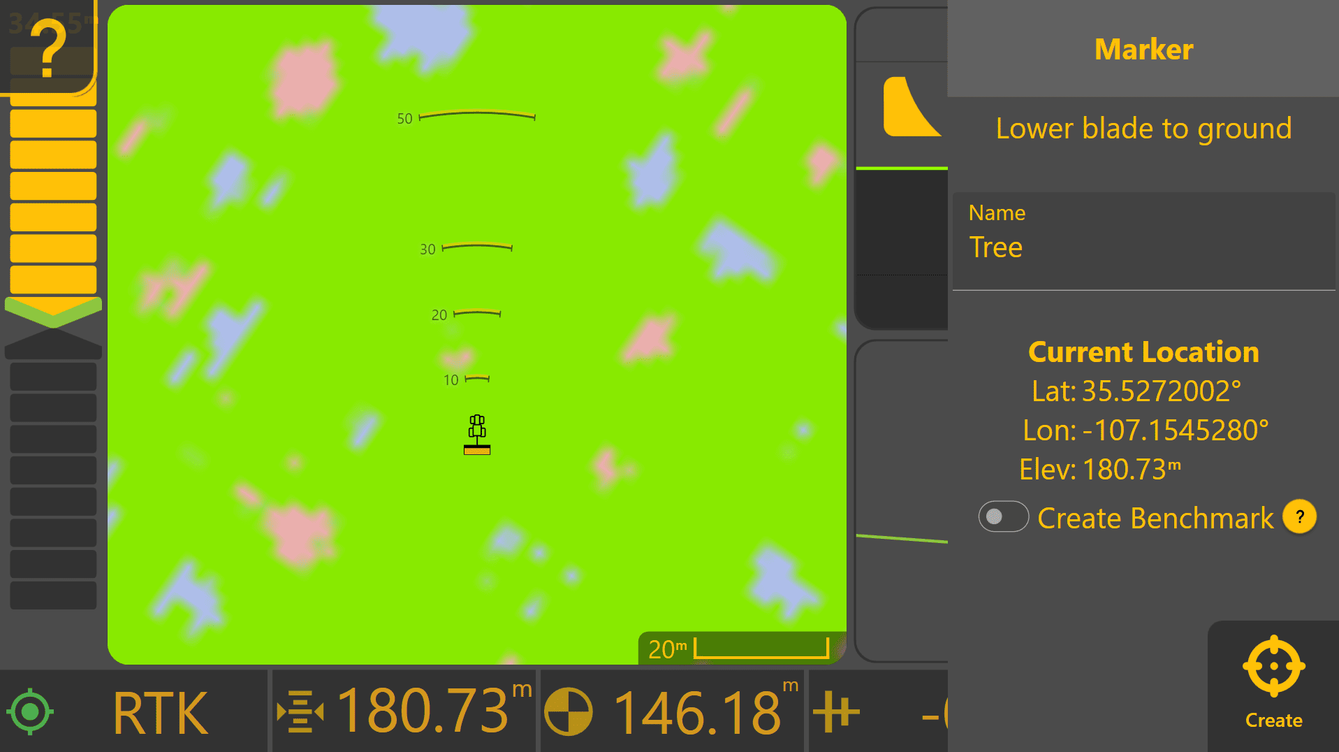
Choosing a Good Benchmark
A Benchmark should be created at a location that can be accurately relocated throughout the life of the project.
Whenever possible, choose a location that:
- Will remain undisturbed during construction.
- Has a flat, stable surface.
- Allows the implement to be positioned accurately.
- Provides sufficient room to safely manoeuvre the machine.
- Can be easily recognised during future visits.
Examples include:
- Concrete pads
- Road shoulders near field entrances
- Survey monuments
- Permanent fence corners
- Other clearly identifiable locations
Avoid locations that are likely to be excavated, filled, cultivated or otherwise disturbed during the project.
When recording a Benchmark from the Apply View, lower the implement onto the ground before creating the marker so the recorded elevation represents the working surface.
Markers During Surveying
Markers can be created at any time, but they are particularly useful while surveying.
Recording important locations before exporting survey data allows those features to become part of the exported project, providing valuable reference information for designers, contractors and future machine operators.
Common markers recorded during a survey include:
- Benchmark locations
- Gateways and access points
- Fence corners
- Irrigation infrastructure
- Power poles and utility crossings
- Trees or significant obstacles
- Drain inlets, outlets and other important field features
Including these reference points within the survey often reduces the need for additional site visits and improves communication between the operator and designer.
When to Create Benchmarks
Creating a new Benchmark is appropriate when:
- Surveying an area for future design work.
- An imported project does not already contain a suitable Benchmark.
- Establishing a permanent reference point for future verification.
When creating a Plane Project, the Plane Origin is automatically stored as a Benchmark Marker and can be used later for re-zeroing the Plane if required.
If an imported project already contains surveyed Benchmarks, these should normally be used instead of creating new ones.
Important Considerations
Creating a Benchmark does not improve GNSS accuracy.
Instead, Benchmarks improve repeatability by allowing the machine to return to the same physical reference point whenever the project is revisited. This helps maintain alignment between the project and the real world over time.
Poorly chosen Benchmark locations may introduce alignment errors if the ground surface changes, the location is disturbed, or the implement cannot be positioned consistently.
Operator Tip: Treat Benchmark Markers as permanent project reference points. Spending a few extra minutes selecting a stable, easy-to-find location can save considerable time when returning to the project months or even years later.
Once you are familiar with creating Markers and Benchmarks, continue to 5.8 | Choosing a Zeroing Method, which explains how different zeroing workflows are selected for Plane Projects, imported designs and existing surfaces.
5.8 | Choosing a Zeroing Method
Selecting the correct zeroing method depends on how the current project was created and whether a suitable Benchmark is available.
The table below summarises the recommended workflow for the most common situations.
| If your project is... | Recommended zeroing method |
|---|---|
| A newly created Plane Project | No additional zeroing is normally required. Defining the Plane Origin using Use GPS establishes the Plane reference. |
| An existing Plane Project being reopened | Zero to the Plane Origin Benchmark if the alignment requires verification or the GNSS reference has changed. |
| An imported design containing Benchmarks | Zero to the supplied Benchmark Marker. This is the preferred method whenever surveyed Benchmarks are available. |
| An imported design without Benchmarks | Create a Benchmark Marker, then perform a Benchmark Zero using the newly created Benchmark. |
| An existing finished surface requiring a small alignment adjustment | Use Set Z to Current to shift the design vertically to the existing surface. This is an advanced workflow and should only be used when appropriate. |
Frequently Asked Questions
Do I need to zero a new Plane Project?
Usually not. When the Plane Origin is created using Use GPS, the Plane is aligned to the current implement position and elevation. The Origin is automatically stored as a Benchmark Marker and can be used later if the Plane needs to be re-zeroed.
Should I create another Benchmark for a Plane Project?
Not normally. The Plane Origin already serves as the primary Benchmark for the Plane.
Additional Benchmarks may be useful on very large sites where returning to the Origin is inconvenient, but they are not generally required.
Should I always use a surveyed Benchmark if one is available?
Yes. Surveyed Benchmarks provide the most repeatable project alignment and should always be preferred over creating a new Benchmark.
When should I create a new Benchmark?
Create a new Benchmark when importing a project that does not already contain one, or when establishing a permanent reference point for future verification and re-zeroing.
When should I use Set Z to Current?
Use Set Z to Current only when aligning a design to an existing finished surface or making a small vertical alignment adjustment.
It should not replace normal Benchmark Zeroing where a suitable Benchmark is available.
How often should I re-zero?
Re-zeroing is normally only required when:
- Returning to a project after a significant period of time.
- Changing or relocating the GNSS base station.
- Alignment is suspected to have changed.
- Project verification indicates the design no longer matches the ground.
Repeatedly zeroing during normal grading is generally unnecessary and may introduce unwanted alignment changes if performed on an unsuitable location.
Operator Tip: Choose one reliable Benchmark and continue using it throughout the project whenever possible. Consistently using the same reference point makes verification easier and helps maintain repeatable project alignment over time.
What's next?
The workflows in this chapter explain how to create projects, collect survey data, place markers and prepare a machine for grading.
The next chapter explains how Level COMMAND interprets this information to control the implement automatically, including surface layers, target generation, predictive control and blade behaviour.
6 | Automatic Control & Surface Behaviour
This chapter explains how Level COMMAND interprets terrain and controls the implement during Automatic Control. It introduces surface layers, target generation, blade control modes, predictive control, GNSS validation and the factors that influence grading performance.
6.1 | Understanding Surface Layers
Every grading operation performed by Level COMMAND is based on one or more surface layers. Although only a single machine is moving across the field, Level COMMAND continuously compares several different representations of the terrain to determine where the implement should be positioned.
Understanding how these surface layers relate to one another makes it much easier to understand Automatic Control, Blade Shift, Cut/Fill Limiting and the information displayed throughout the Apply View.
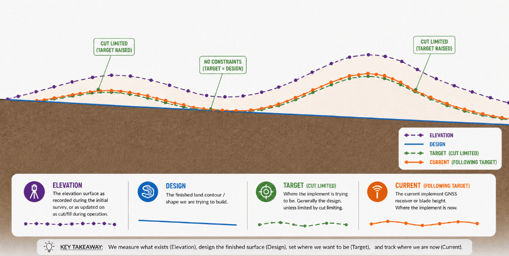
The diagram above illustrates the relationship between the four primary surface layers used during grading. Although each layer serves a different purpose, they work together to guide the implement towards the finished design.
Existing Ground (Elevation)
The Elevation surface represents the terrain as it currently exists.
This surface is typically created by surveying the work area before grading begins, although it may also be imported as part of a pre-designed project. The Elevation surface records the natural shape of the ground, including slopes, depressions and other terrain features.
As grading progresses, the original Elevation surface remains unchanged and continues to represent the ground before any earthmoving took place.
Design Surface
The Design surface represents the desired finished ground profile.
It may be:
- Created directly within Level COMMAND using a Plane Project.
- Imported from external design software as part of a pre-designed project.
Unlike the Elevation surface, the Design surface normally remains unchanged throughout the grading operation. It defines the final surface that the operator is working towards.
Target Position
The Target surface is the position that Level COMMAND is currently attempting to guide the implement towards.
Under normal operation, the Target surface is derived from the Design surface. Depending on the selected control mode and operator settings, the Target may temporarily differ from the Design while still guiding the implement toward the same finished result.
Examples include:
- Blade Shift
- Dynamic Cut Limiting
- Dynamic Fill Limiting
- Blade Control Modes
This distinction is important. Level COMMAND maintains the relationship between the implement and the current Target surface, while the Design surface remains the long-term grading objective.
Current Position
The Current position represents the measured location of the implement relative to the Target surface.
As the machine moves, Level COMMAND continually compares the Current position with the Target surface to determine whether the implement needs to raise, lower or maintain its present position.
The difference between the Current position and the Target surface is referred to as the Current Error, which is displayed throughout the Apply View and used by Automatic Control.
Surface Interpolation
Survey data consists of individual measured points rather than a continuous surface.
To create a usable grading model, Level COMMAND interpolates between the recorded survey points to form a continuous terrain surface. This allows the system to determine elevations at locations between individual survey measurements.
The quality of this surface depends on the quality of the original survey.
Generally:
- Higher survey density produces a more accurate representation of the terrain.
- Sparse survey data may smooth or omit smaller terrain features.
- Poor-quality survey data cannot be fully corrected by Automatic Control during grading.
For this reason, accurate surveying is an important foundation for achieving accurate grading results.
Surface Updates During Grading
Not every surface changes during operation.
| Surface | Updated During Grading |
|---|---|
| Elevation | No (represents the original surveyed ground) |
| Design | No (represents the desired finished surface) |
| Target | Yes (may change due to Blade Shift, Cut/Fill Limiting or other operating modes) |
| Current | Continuously (tracks the live implement position) |
| As Applied Elevation | Yes (records the surface produced during grading) |
| As Applied Cut/Fill | Yes (records remaining cut and fill after grading progress) |
The As Applied surfaces provide a continuously updated representation of the work being performed. These are the surfaces displayed when viewing the As Elevation or As Cut/Fill map layers in the Apply View, allowing operators to monitor grading progress as work is completed.
Operator Tip: Think of the surface layers as answering five different questions:
Elevation — What does the ground look like today?
Design — What do I want it to look like when I'm finished?
Target — Where should the implement be right now?
Current — Where is the implement right now?
As Applied — What have I actually built so far?
Once you understand how these surface layers interact, the operation of Automatic Control, Blade Control Modes, Blade Shift and the other features described throughout this chapter becomes much easier to understand.
6.2 | Automatic Blade Control
Automatic Blade Control is the process Level COMMAND uses to guide the implement towards the required target position while grading.
Once Automatic Control is engaged, Level COMMAND continually monitors the implement position, compares it with the required target position and sends control commands to the COMMAND ECU. The COMMAND ECU then operates the configured hydraulic outputs to move the implement as required.
This process repeats continuously while Automatic Control remains engaged.
Control Overview
During normal operation, Level COMMAND continually performs the following control process:
- Determine the current implement position.
- Determine the required target position.
- Compare the current position with the target position.
- Calculate the current control error.
- Send the required control command to the COMMAND ECU.
- Measure the new implement position.
- Repeat the process as the machine moves.
This continuous feedback allows Level COMMAND to respond to changing terrain and maintain accurate control throughout the grading operation.
Closed-Loop Control
Automatic Blade Control is a closed-loop control system.
Rather than commanding the implement to move once and assuming the correct position has been reached, Level COMMAND continually measures the implement position and updates hydraulic commands until the implement is tracking the target position correctly.
This continuous feedback allows the system to compensate for changing ground conditions and maintain accurate grading performance.
What Determines the Target Position?
The target position is derived from the loaded design together with any active operator settings.
Depending on the current grading task, the target position may be influenced by:
- Design surface
- Blade Shift
- Dynamic Cut Limiting
- Dynamic Fill Limiting
Because of this, the target position may not always be identical to the final design surface at that moment. However, the objective remains the same: to guide the implement smoothly towards the intended finished surface.
Hydraulic Response
Hydraulic systems require a small amount of time to respond to control commands. As a result, the implement does not move instantly when the target position changes.
Instead, Level COMMAND continuously monitors implement position and adjusts hydraulic output as the machine moves. This produces smooth, stable grading while allowing the implement to progressively converge on the target position.
Later in this chapter, Look Ahead is introduced as one method used to further improve tracking performance by anticipating changes in terrain.
When the Implement Is Far from Target
The amount of hydraulic correction applied depends on how far the implement is from the target position.
When close to the target, COMMAND makes small corrections to accurately maintain grade.
When further from the target, larger corrections may be applied to return the implement more quickly.
If the implement moves beyond the configured operating range, automatic movement may be suspended until the operator manually returns the implement closer to the working surface.
Operator Responsibility
Automatic Control assists with implement positioning, but the operator remains responsible for machine operation.
The operator must still:
- Choose the travel path.
- Manage material movement.
- Maintain safe travel speed.
- Monitor cut/fill behaviour.
- Watch for obstacles, people and changing ground conditions.
- Disengage Automatic Control if machine behaviour is unexpected.
Level COMMAND can guide the implement towards the target position, but it does not determine the overall earthmoving strategy. Efficient grading still depends on good operator judgement and planning.
Continue to 6.3 | Blade Control Modes to learn how Level COMMAND determines the target position beneath the blade for different grading situations.
6.3 | Blade Control Modes
Blade Control Modes determine how Level COMMAND interprets the design surface beneath the blade when calculating the required target position.
Different grading situations benefit from different control strategies. Some modes prioritise accurately following the design, while others minimise overcutting or improve performance around sudden changes in terrain.
Selecting the appropriate Blade Control Mode can improve grading efficiency, reduce rework and produce a more consistent finished surface.
The available Blade Control Modes are described below.
Classic
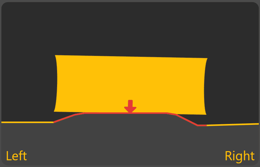
Classic uses the design elevation directly beneath the centre of the blade as the target position.
For Height & X-Slope applications, cross-slope is calculated using the design elevations beneath the left and right edges of the blade.
This mode follows the design exactly but may overcut when crossing sudden changes in terrain, such as ditch centres or sharp breaklines.
Typical applications include:
- General grading on smooth surfaces.
- Areas with gradual changes in terrain.
Average
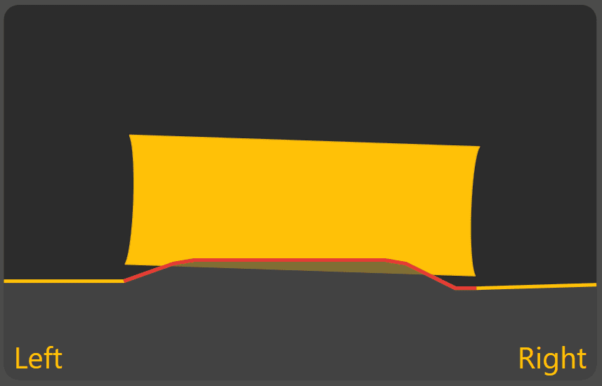
Average determines the overall trend of the design surface beneath the blade and positions the blade to follow that average profile.
This produces smooth grading performance across broad, continuous surfaces and reduces sensitivity to small variations in the design.
Typical applications include:
- Broadacre landforming.
- Large paddocks.
- Surfaces with gradual, continuous grades.
Average On Top

Average On Top uses the same averaging method as Average, but positions the blade to avoid cutting below the design surface.
This helps prevent overcutting while maintaining smooth grading performance.
Typical applications include:
- Finishing passes.
- Projects where preserving the design surface is more important than maximising material removal.
- Areas where overcutting must be avoided.
Snap Fit

Snap Fit determines the blade position that best matches the design while avoiding unnecessary overcutting.
When crossing abrupt changes in terrain, such as breaklines or drain batters, the blade rapidly transitions between adjacent design surfaces rather than averaging across them.
This allows sharp design features to be maintained while reducing unnecessary passes.
Typical applications include:
- Drain construction.
- Batters.
- Breaklines.
- Designs containing abrupt changes in grade.
Single Point
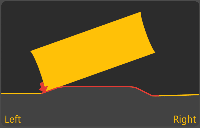
Single Point controls a single selected point on the blade rather than considering the full blade width.
The selected control point is maintained on the design surface even though other parts of the blade may be above or below the design.
This mode is particularly useful for constructing features where one point of the blade must accurately follow the design.
Typical applications include:
- V-drains.
- Channels.
- Working against existing edges.
- Precision grading using one side of the blade.
When Single Point is active, the Swap Ctrl button is displayed in the Back View. This allows the active control point to be quickly swapped between the left and right sides of the blade when changing travel direction.
Choosing a Blade Control Mode
No single Blade Control Mode is ideal for every grading task.
Broad, continuous grading generally benefits from Average or Average On Top, while projects containing drains, batters or sharp terrain changes are often better suited to Snap Fit or Single Point.
Operators should select the mode that best matches the design being constructed and the type of grading being performed.
Continue to 6.4 | Blade Shift & Material Control to learn how the target position can be temporarily adjusted during grading without modifying the underlying design.
6.4 | Blade Shift & Target Adjustment
Blade Shift allows the operator to temporarily adjust the Target Position during grading.
This provides a quick method of making small grading adjustments to suit changing site conditions without changing the project itself.
Blade Shift changes the current Target—not the Design. Remove the applied shift at any time to return Automatic Control to the original design surface. If large Blade Shift values become necessary, verify the project alignment and consider performing Zero instead.
To access the Blade Shift controls from the Apply View:
Press Blade Shift.
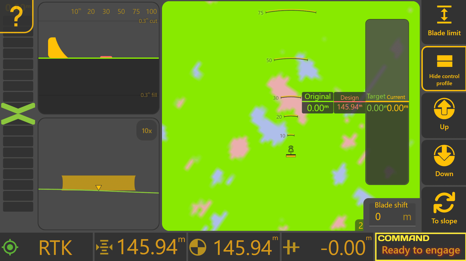
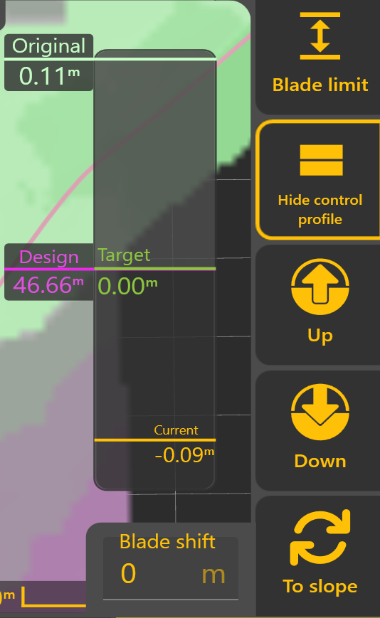
Understanding the Control Profile
The Control Profile provides a live cross-sectional view of the current grading state. It allows the operator to see how the original ground, Design, Target Position and current implement position relate to one another during Automatic Control.
The Control Profile displays four key references:
Original
The original surveyed ground surface before grading began, shown relative to the Design.
Design
The intended finished surface. This remains fixed throughout the project and represents the final grading objective.
Target
The position currently being tracked by Automatic Control.
Normally, the Target matches the Design. However, Blade Shift or Dynamic Cut & Fill Limiting may temporarily adjust the Target during grading.
Current
The current implement position relative to the Design.
As Automatic Control operates, the Current position should progressively move towards the Target.
 Blade Shift
The Up and Down buttons temporarily raise or lower the Target by the configured Blade Shift Increment.
Multiple adjustments can be applied as required, and the current Blade Shift value is displayed within the Blade Shift window. Selecting the displayed value allows a specific offset to be entered directly.
Dynamic Cut & Fill Limiting
 Dynamic Cut & Fill Limiting temporarily restricts how much material Automatic Control attempts to remove or place during a single pass.
Rather than immediately targeting the finished Design, Level COMMAND calculates a temporary Target Position that respects the configured Cut or Fill Limit. As grading progresses, the Target automatically moves towards the Design until the finished surface is achieved.
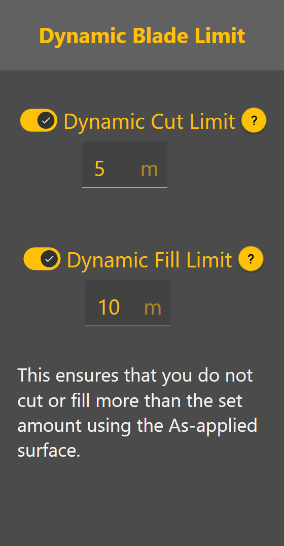 Dynamic Cut & Fill Limiting is useful for:
- Removing material over multiple controlled passes.
- Reducing machine load.
- Preventing excessive cutting or filling in a single pass.
- Improving control on difficult ground.
 Manual X-Slope Adjustment
Machines equipped with Height & X-Slope control can temporarily adjust the target cross-slope.
Select To Slope to switch from Blade Shift controls to X-Slope controls.
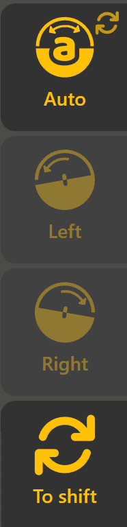
When X-Slope Auto is enabled, Level COMMAND automatically follows the Design cross-slope. When Auto is disabled, the operator may manually adjust the target cross-slope using the Left and Right controls or enter a specific value directly.
Select To Shift to return to the Blade Shift controls.
Blade Shift Increment
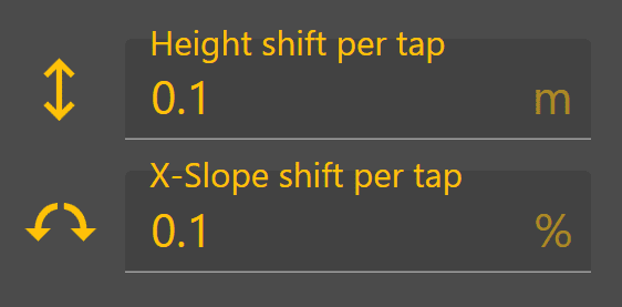
The amount applied by each press of the Up or Down buttons is determined by the configured Blade Shift Increment. Likewise, manual X-Slope adjustments use the configured X-Slope Shift Increment.
To change the Blade Shift Increment, from the Apply View press:
More → Blade Shift Settings
Smaller increments provide finer control, while larger increments allow quicker adjustments during grading.
Typical Blade Shift Increment values are:
| Units | Recommended Increment |
|---|---|
| Metres | 0.01–0.02 m |
| Inches | 0.4–0.8 in |
| Feet | 0.03–0.06 ft |
These values provide a good balance between adjustment precision and operating efficiency for most grading applications.
Operator Tip: Use Blade Shift to make temporary grading adjustments as conditions change throughout the day. If large Blade Shift values become necessary to maintain the desired grade, verify the project alignment and consider performing Zero again rather than continuing to increase the applied offset.
Continue to 6.5 | Position Quality & GNSS Validation to understand how Level COMMAND validates positioning information before Automatic Control is allowed to operate.
6.5 | Reliable Positioning
The accuracy of Automatic Control depends directly on the quality of the positioning information received from the GNSS receivers.
Every control decision made by Level COMMAND begins with a measured implement position. If that position is inaccurate, the calculated Target Position, Current Error and hydraulic commands will also become inaccurate.
Why Position Quality Matters
 Throughout this manual, Automatic Control has been described as continually comparing the Current Position with the Target Position.
This comparison is only meaningful if the Current Position accurately represents the true location of the implement.
Poor positioning can result in:
- Incorrect cut or fill values.
- Unnecessary hydraulic movement.
- Reduced grading accuracy.
- Poor finished surfaces.
- Unstable Automatic Control.
Although Level COMMAND continuously validates incoming positioning information, it cannot improve the accuracy of incorrect or poor-quality GNSS measurements.
Position Validation
Before Automatic Control is permitted to operate, Level COMMAND verifies that the received positioning information meets the configured operating requirements.
Typical validation checks include:
- Receiver communication.
- IMU availability (where fitted).
- Position update rate.
- RTK positioning quality.
- Position stability.
If one or more validation requirements are not satisfied, COMMAND Status reports the reason and Automatic Control may be prevented from engaging or may disengage until valid positioning information is restored.
Monitoring GNSS Operation
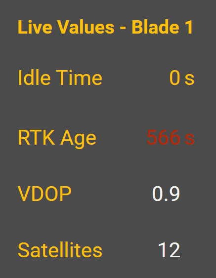 During normal operation, COMMAND Status provides the primary indication of GNSS-related operating conditions. Depending on the situation, COMMAND Status may report messages such as:
- Waiting for RTK before Automatic Control can be engaged.
- Loss of RTK if RTK positioning is lost during operation.
- Unstable GPS or IMU if the measured position or orientation becomes unreliable.
Additional live GNSS information can be viewed from:
More → COMMAND Settings → GPS Thresholds
This page displays live receiver information including RTK status, Satellite Count, VDOP and RTK Age, allowing the operator or dealer to confirm that the GNSS system is operating as expected.
When Further Investigation May Be Required

If positioning quality remains poor, the cause often lies outside Level COMMAND itself.
Further investigation may be required if:
- RTK cannot be achieved.
- RTK is repeatedly lost during operation.
- Surveyed elevations appear inconsistent.
- Automatic Control repeatedly disengages due to positioning quality.
- COMMAND Status repeatedly reports GNSS or IMU warnings.
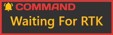 Depending on the installation, this may require checking:
- GNSS receiver configuration.
- Base station operation.
- Radio or correction link performance.
- Receiver antenna installation.
- Machine wiring and communication.
These components provide the positioning information used by Level COMMAND and should be operating correctly before investigating Automatic Control performance.
Good Operating Practice
For the best grading performance:
- Wait until RTK positioning has been achieved before beginning work.
- Verify COMMAND Status displays Ready to Engage.
- Investigate repeated RTK loss before continuing work.
- Confirm receiver and base station configuration if persistent positioning issues occur.
Operator Tip: If grading accuracy suddenly deteriorates, verify the quality of the GNSS solution before adjusting control settings or recalibrating the machine. Many apparent control problems are ultimately caused by poor positioning rather than incorrect Automatic Control settings.
Continue to 6.6 | Automatic Control Tuning to learn how Level COMMAND can be optimised once reliable positioning has been established.
6.6 | Automatic Control Tuning
The quality of Automatic Control is determined by several systems working together. Poor grading performance is often caused by multiple small issues rather than a single fault.
Rather than immediately adjusting tuning or calibration values, verify that each stage of the control process is operating correctly.
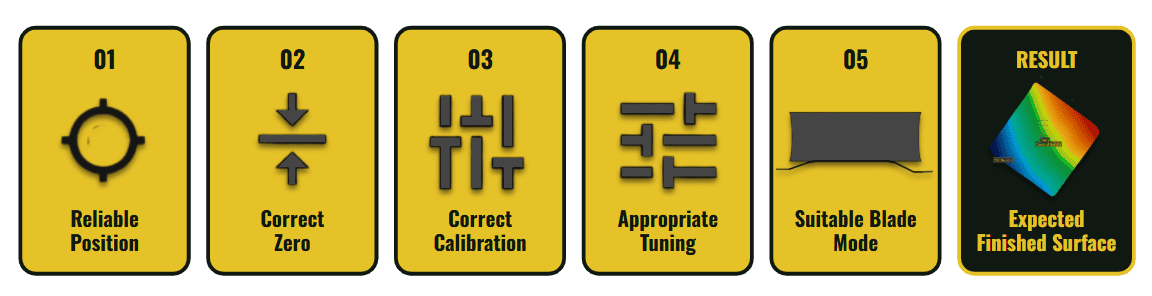
The diagram above shows the recommended order for evaluating Automatic Control performance. Each stage provides the foundation for the next. Problems identified early in the process should be corrected before moving on to later stages.
| Factor | Why It Matters |
|---|---|
| Reliable Position | Accurate GNSS positioning is the foundation of Automatic Control. Poor position data cannot be corrected through tuning or calibration. |
| Correct Zero | Zero aligns the project with the real world. An incorrect Zero causes every calculated Target Position to be offset from the intended Design. |
| Correct Calibration | Correct valve calibration ensures the hydraulic system begins moving at the expected output and reaches full output when required. Incorrect calibration often produces symptoms similar to poor tuning. |
| Appropriate Tuning | Once calibration is correct, Tracking Sensitivity fine-tunes how aggressively the implement responds to changing conditions. Small adjustments are normally sufficient. |
| Suitable Blade Control Mode | Selecting the appropriate Blade Control Mode allows Level COMMAND to interpret the Design in a way that best suits the grading task and terrain. |
| Good Finished Surface | When each stage is functioning correctly, Automatic Control can consistently produce accurate and repeatable grading results. |
Other Influencing Factors
Even when the control system has been configured correctly, external operating conditions can still affect grading performance.
Examples include:
- Machine travel speed.
- Hydraulic flow and pressure.
- Implement size and weight.
- Soil conditions and material consistency.
- Machine wear or hydraulic leakage.
These factors influence how quickly and accurately the implement can respond to hydraulic commands generated by Level COMMAND.
Diagnosing Poor Performance
If grading performance is not meeting expectations, investigate the system in the order shown above.
For example:
- Poor RTK positioning should be corrected before recalibrating the hydraulic system.
- Incorrect Zero should be corrected before adjusting Tracking Sensitivity.
- Valve calibration should be verified before attempting further tuning.
- Blade Control Mode should only be changed once the control system is operating correctly.
Working through the control system in this sequence avoids unnecessary adjustments and makes faults significantly easier to identify.
Operator Tip: Make one adjustment at a time. Changing multiple settings together makes it difficult to determine which change improved—or degraded—control performance. Verify the effect of each adjustment before making the next.
Continue to 6.7 | Predictive Control & Look Ahead to learn how Level COMMAND anticipates machine movement and compensates for hydraulic response delays.
6.7 | Look Ahead
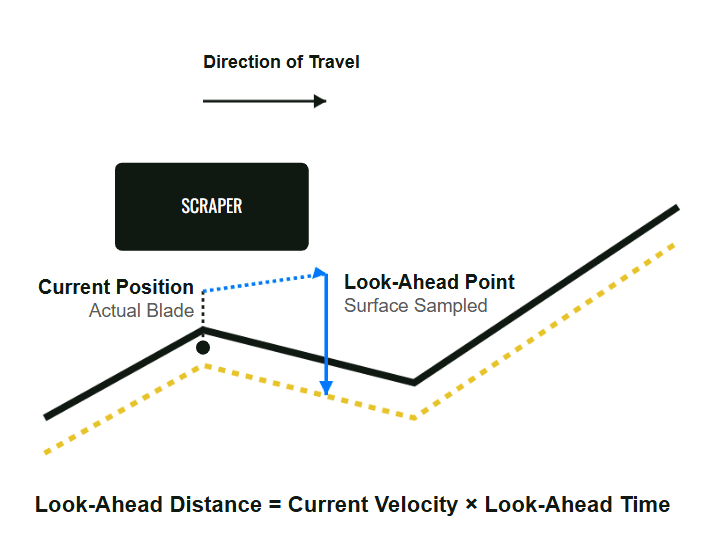
Hydraulic systems require a short amount of time to respond after a control command is issued. Oil must flow, hydraulic cylinders must move and the implement must physically react before the blade reaches its new position.
To compensate for this delay, Level COMMAND uses Look Ahead.
Rather than waiting until the implement reaches a change in the Design, Level COMMAND begins commanding hydraulic movement slightly in advance so the implement reaches the correct position at the appropriate time.
This predictive behaviour helps produce smoother, more accurate grading, particularly when operating at higher travel speeds or over changing terrain.
How Look Ahead Affects Grading
The amount of Look Ahead determines how early Automatic Control begins responding to upcoming changes in the Design.
Too Little Look Ahead
If the Look Ahead value is too small, the hydraulic system may respond too late.
Typical symptoms include:
- The implement reacts after reaching changes in the Design.
- Rounded crests or delayed transitions.
- Persistent tracking error.
- Reduced grading accuracy at higher travel speeds.
Too Much Look Ahead
If the Look Ahead value is too large, the hydraulic system may respond earlier than necessary.
Typical symptoms include:
- The implement begins lifting or lowering too early.
- Overcorrection approaching changes in terrain.
- Reduced grading accuracy around abrupt transitions.
Adjusting Look Ahead
The Look Ahead setting can be accessed from:
More → Diagnostics/Advanced
For most machines, the default value provides good performance and should not normally require adjustment.
Changes should only be made after confirming:
- Reliable RTK positioning.
- Correct Zero.
- Correct valve calibration.
- Appropriate Tracking Sensitivity.
Adjusting Look Ahead before these items have been verified may make diagnosing control performance more difficult.
Operator Tip: Treat Look Ahead as an advanced tuning parameter. If Automatic Control is performing well, leave the default setting unchanged. Adjust it only when there is a clear reason to do so and after the rest of the control system has been verified.
Continue to 6.8 | Tandem & Multi-Blade Behaviour to understand how Level COMMAND manages machines with multiple control points and implements.
6.8 | Tandem Blade Behaviour
The Tandem Scraper profile allows Level COMMAND to control two trailing scrapers independently during the same grading operation.
Although each scraper is controlled separately, the overall operating workflow remains almost identical to a single scraper. Most setup, calibration and operating procedures described throughout this manual apply equally to both blades.

Independent Control
Each scraper maintains its own control solution based on its individual position and configuration.
Each scraper has independent:
- GNSS receiver configuration.
- Receiver offsets.
- Look-Ahead calculation.
- Blade Position calculation.
- Automatic Control output.
- Dynamic Cut & Fill Limiting.
This allows each scraper to respond correctly to the terrain beneath it, even though both are working as part of the same machine.
Shared Adjustments
Some operator adjustments intentionally affect both scrapers together.
For example:
- Blade Shift applies the same vertical offset to both blades.
- Project Zero applies to the entire machine.
- The selected Blade Control Mode applies consistently across the machine profile.
This keeps both scrapers working toward the same finished design while still allowing each blade to respond independently to local terrain.
 Monitoring Both Scrapers

When using the Tandem Scraper profile, the Apply View displays two On-Grade Indicators—one for each scraper.
image.png
Each indicator displays the grading error for its respective scraper, allowing the operator to quickly confirm that both blades are tracking their Target Positions correctly.
Additional widgets are also available for monitoring the individual position and performance of each scraper where required.
Commissioning a Tandem Machine
Commissioning a Tandem Scraper follows the same process as commissioning a single scraper.
Each scraper should be configured and calibrated individually, including:
- GNSS configuration.
- Receiver offsets.
- Hydraulic calibration.
- Automatic Control tuning.
Once both scrapers have been configured, they operate together as a single machine profile.
Operator Tip: Treat each scraper as an independent Automatic Control system. Although both blades work toward the same finished surface, each one must be correctly configured and calibrated to achieve the best overall grading performance.
Chapter Summary: Throughout this chapter you've seen how Level COMMAND interprets the design surface, calculates the Target Position and continuously adjusts the implement to achieve a smooth, accurate finished result. Understanding these Automatic Control concepts makes it easier to interpret system behaviour and recognise how positioning, calibration, tuning and machine configuration influence grading performance. The next chapter builds on this foundation by covering the more detailed aspects of machine setup, calibration and advanced system configuration.
7 | Settings & Preferences
This chapter describes the application settings used to customise the Level COMMAND user experience. It covers display preferences, measurement units, language, software updates, licensing, support tools and advanced application settings.
7.1 | Appearance
The Appearance page allows you to customise how Level COMMAND is displayed. These settings only affect the user interface and map presentation—they do not change how the guidance or automatic control system operates.
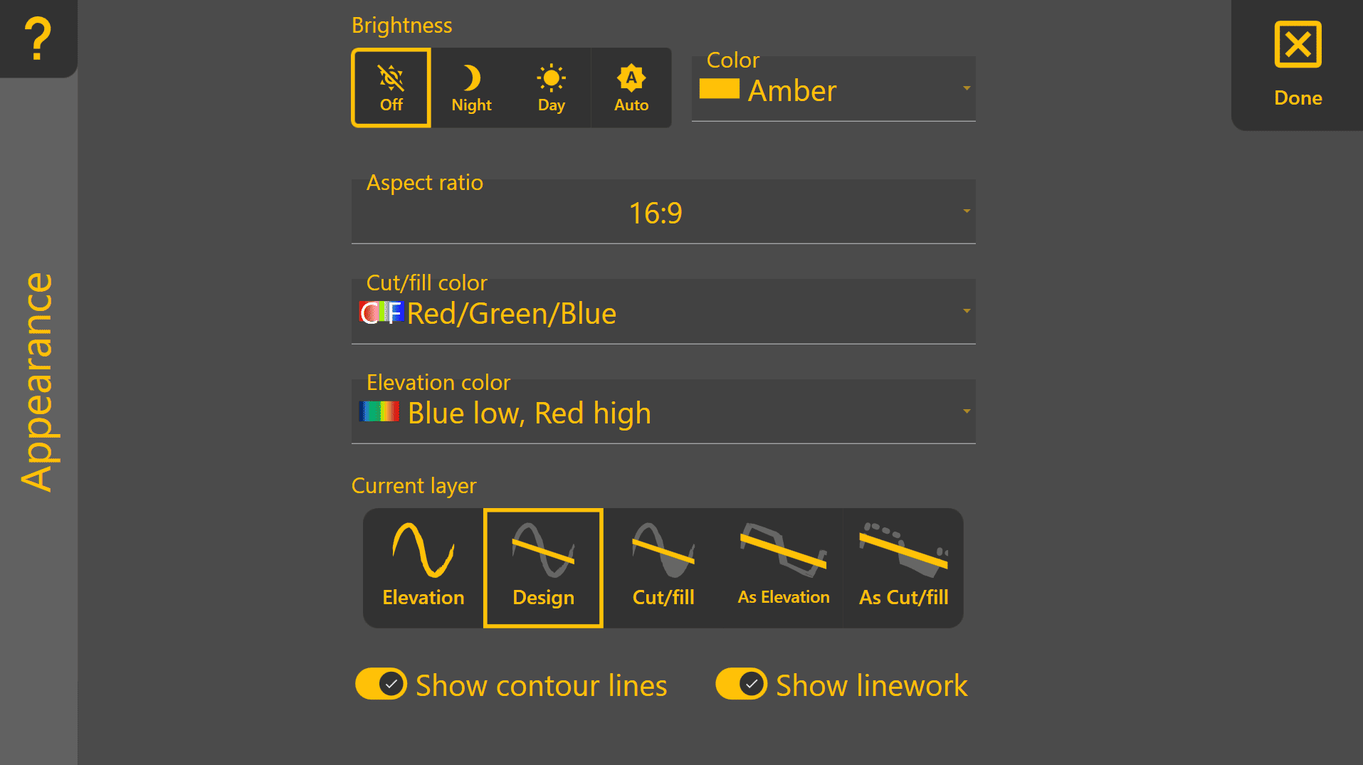
Brightness
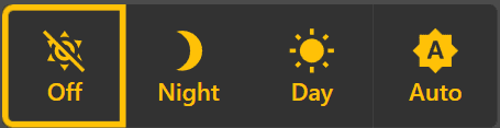
Adjusts the display brightness to suit different lighting conditions.
- Off – Level COMMAND does not control screen brightness.
- Night – Reduces brightness for comfortable viewing in low-light conditions.
- Day – Sets the display to maximum brightness.
- Auto – Automatically adjusts brightness based on the current time and location, dimming at sunset and brightening at sunrise.
 Theme Colour

Selects the primary colour used throughout the Level COMMAND interface.
Aspect Ratio
Optimises the interface layout for your display.
Select the aspect ratio that best matches your device:
- 16:9
- 16:10

Cut/Fill Colour Scheme
Selects the colours used to display Cut/Fill maps.
Two colour schemes are available:
- Magenta / Green – Magenta represents cut areas and green represents fill areas.
- Red / Green / Blue – Red represents cut, green represents on-grade, and blue represents fill.
The Magenta / Green scheme may be easier to distinguish for some users with red-green colour vision deficiency, while Red / Green / Blue provides a clearer visual indication of areas already on grade.

Elevation Colour Scheme
Changes the colour palette used to display elevation maps.
Different colour schemes may improve visibility depending on personal preference or lighting conditions.

Current Map Layer
Selects which project layer is displayed on the map.
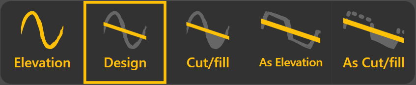
Available layers include:
- Elevation – Displays the original surveyed ground surface before any earthworks have been carried out.
- Design – Displays the design surface that the machine is working towards.
- Cut/Fill – Shows where material must be cut or filled relative to the original elevation surface.
- As Elevation – Displays the measured surface as work progresses, providing a live representation of completed earthworks. Contour lines are not displayed for this layer.
- As Cut/Fill – Displays the remaining cut and fill required by comparing the current surface with the design surface. Contour lines are not displayed for this layer.
Show Contour Lines

Enables or disables contour lines on supported map layers.
Contour lines are available for Elevation, Design, and Cut/Fill layers. They are not shown for As Elevation or As Cut/Fill, as these layers update continuously while work is being performed.
Show Linework

Shows or hides imported project linework on the map.
Turning linework off can simplify the display when working with projects containing a large number of lines or boundaries.
7.2 | Units
The Units page allows you to select the measurement units used throughout Level COMMAND.
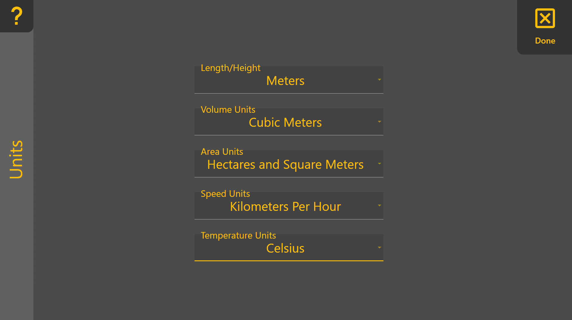
The available unit categories are:
- Length / Height – Millimetres, Centimetres, Metres, Inches, or Feet.
- Volume – Cubic Metres, Cubic Yards, or Cubic Feet.
- Area – Hectares and Square Metres, or Acres and Square Feet.
- Speed – Metres per second, Feet per second, Metres per minute, Feet per minute, Metres per hour, Kilometres per hour, or Miles per hour.
- Temperature – Degrees Celsius or Degrees Fahrenheit.
For the best experience, restart Level COMMAND after changing any unit settings to ensure all displays are updated consistently.
7.3 | Language & Accessibility
The Language & Accessibility page allows you to customise the interface language and on-screen keyboard behaviour to suit your device and operating preferences.
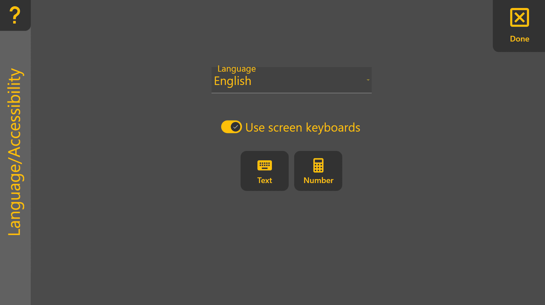
Language
Selects the display language used throughout Level COMMAND.

For the best experience, restart Level COMMAND after changing the language.
Use Screen Keyboards
When enabled, Level COMMAND automatically opens the appropriate on-screen keyboard whenever text or numeric input is required.
This setting is particularly useful when using tablets or touchscreen devices without a physical keyboard.

Keyboard Test

The Show for Text and Show for Number buttons allow you to verify that the configured on-screen keyboards are operating correctly.
- Show for Text – Opens the text keyboard.
- Show for Number – Opens the numeric keypad.
These options are intended as a quick test if the on-screen keyboard is not appearing as expected.
If the On-Screen Keyboard Does Not Appear
If the Windows on-screen keyboard does not open automatically:
- Verify that Use Screen Keyboards is enabled.
- Confirm that the Windows on-screen keyboard is installed and enabled.
- Connect a physical keyboard if required.
Refer to the Microsoft Windows documentation for additional information about configuring on-screen keyboards.
7.4 | Updates & Release Management
The Update/Changelog page allows you to keep Level COMMAND up to date and review changes introduced in each software release.
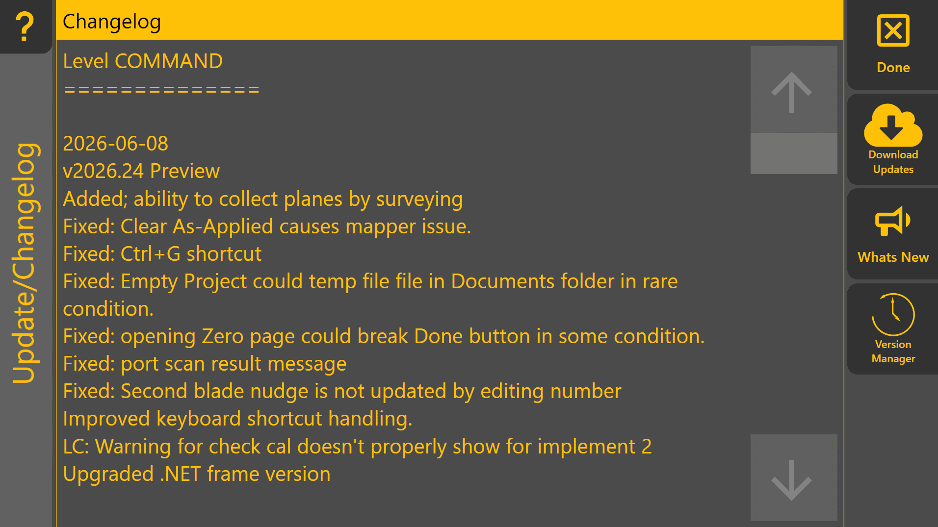
Keeping the software current provides access to new features, performance improvements and bug fixes. However, if the system is operating reliably during an active project, consider postponing updates until the project has been completed.
Changelog
The Changelog displays the release notes for the currently installed version of Level COMMAND.
Reviewing the changelog allows operators and dealers to understand what has changed between software versions, including new features, improvements and resolved issues.
 Download Updates

Downloads and installs the latest available version of Level COMMAND.
An active internet connection is required.
Before updating, ensure the machine is not actively being used for production work.
 What's New

Displays the release notes for the latest available software version before installation.
This allows you to review new features, improvements and resolved issues when deciding whether to update.
 Version Manager
The Version Manager allows previously installed versions of Level COMMAND to be restored if required.
Rolling back to an earlier version should generally only be performed for compatibility purposes or under the guidance of T3RRA Support.
If a previous version is required due to unexpected behaviour after an update, consider submitting a diagnostic report so the underlying issue can be investigated.
Unable to Check for Updates
If Download Updates or What's New cannot be accessed:
- Verify that an internet connection is available.
- Confirm that any firewall or network restrictions permit access to the update service.
- Refer to 8 | Diagnostics & Troubleshooting if the problem persists.
7.5 | Licensing
The Licensing page is used to activate Level COMMAND and register the software for normal operation.
To open the Licensing page, press More → License.
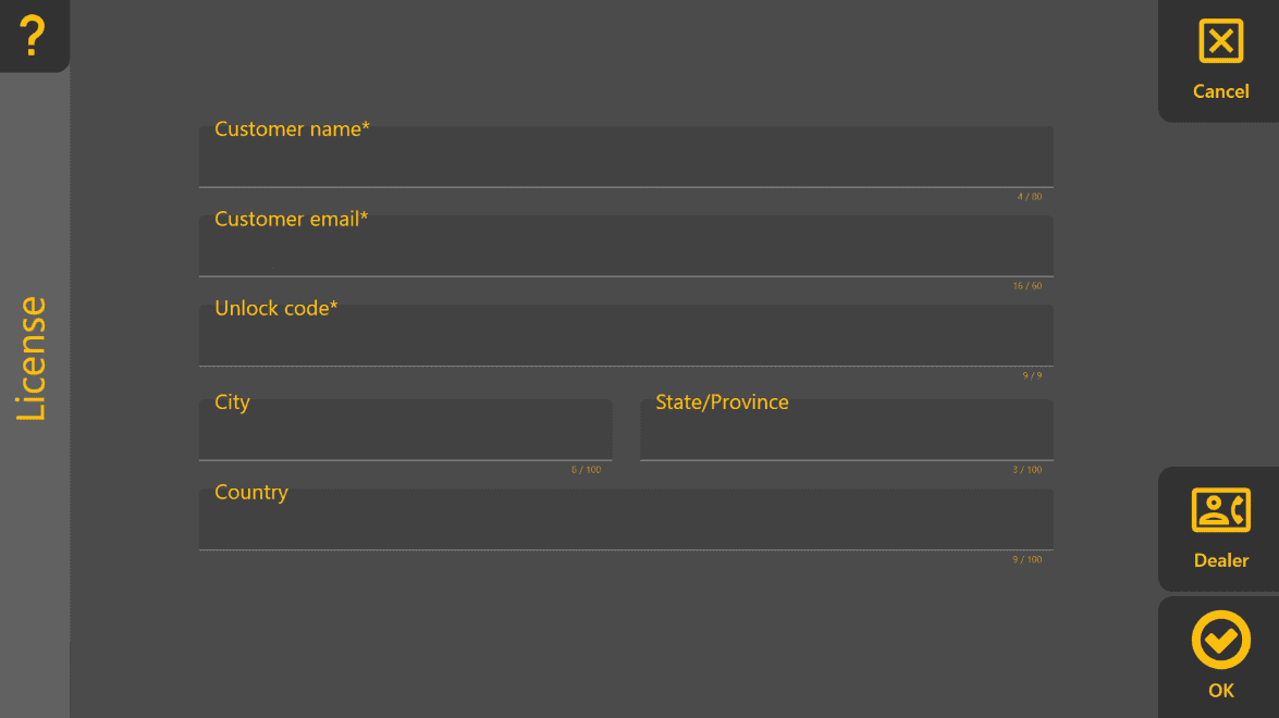
A valid licence is required for normal operation. If Level COMMAND has not been activated, a Demo Mode banner is displayed across the top of the Apply View.
Activating Level COMMAND
To activate the software:
- Press More → License.
- Enter the required customer information.
- Enter the supplied Unlock Code.
- Press OK.
The customer email address is used for licensing and product-related communication where required.
Dealer Information
Press Dealer to view the contact details of the authorised T3RRA dealer responsible for supplying or supporting the system.
This information can be useful when requesting assistance with:
- Software activation.
- Product support.
- Installation or commissioning.
- Technical enquiries.
If Activation Fails
If Level COMMAND cannot be activated:
- Verify that the Unlock Code has been entered correctly.
- Confirm that all required fields have been completed.
- Contact your authorised T3RRA dealer if the problem persists.
7.6 | Support & Error Reporting
The Support & Error Reporting tools allow operators and dealers to receive remote assistance and provide feedback directly to T3RRA.
To access the Error Reporter, press More → Report.
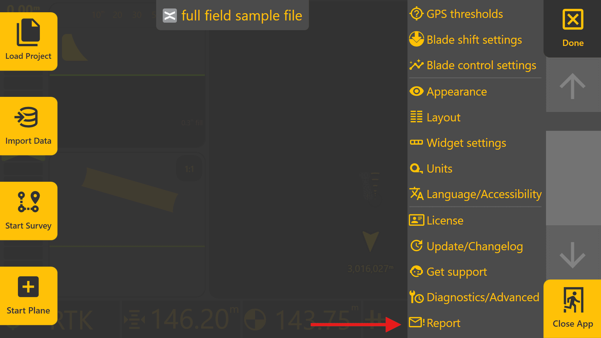
An internet connection is required for Remote Support and sending reports.
Error Reporter
The Error Reporter allows bug reports, feature requests and other feedback to be submitted directly to T3RRA.
Your name and email address are automatically populated using the information entered on the License page.
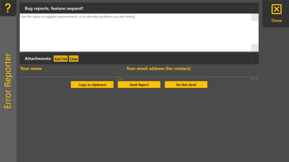
Creating a Report
For the most useful reports:
- Clearly describe the issue or requested feature.
- Include the steps that led to the problem.
- Explain what you expected to happen and what actually occurred.
- Attach screenshots, project files or log files where available.
Supporting files can be added using Add File.
Sending or Saving a Report
The Error Reporter provides three options:
| Option | Purpose |
|---|---|
| Send Report | Sends the report and any attached files directly to T3RRA. |
| Copy to Clipboard | Copies the report contents to the clipboard for pasting into an email or other support request. |
| Do Not Send | Closes the Error Reporter without submitting the report. |
After selecting Send Report, do not close Level COMMAND until confirmation is displayed indicating that the report has been sent successfully. Closing the application too early may prevent attached files from being uploaded.
Operator Tip: The more information included with a report, the easier it is to reproduce and investigate. If possible, include screenshots, project files, log files and a clear description of the steps leading up to the issue.
Remote Support
Remote Support allows your authorised dealer to assist with troubleshooting and system configuration without requiring direct access to the machine.
To enable Remote Support:
- Press More → Get Support.
- Select Setup Remote Support.
- Wait while the Remote Support application is downloaded and installed.
- Provide the displayed support code to your dealer.
Once connected, your dealer can assist with diagnosing configuration issues and investigating system behaviour.
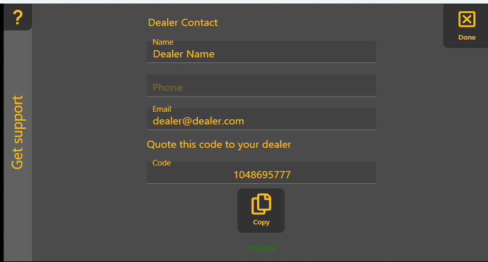
The Setup Remote Support button is only displayed if the Remote Support application has not already been installed.
7.7 | Diagnostics / Advanced
The Diagnostics & Advanced page provides access to advanced application settings, diagnostic tools and project information.
To open this page, press More → Diagnostics / Advanced.

Most options on this page are intended for dealers, advanced users or troubleshooting with the assistance of T3RRA Support. Unless instructed otherwise, the default settings are recommended.
Application Settings
Several application behaviours can be configured from this page, including:
- Start Level COMMAND when the computer starts – Automatically launches Level COMMAND when Windows starts.
- Enable GPS Data Log – Records GNSS data for later analysis and troubleshooting.
- Enable Diagnostic Data – Collects diagnostic information that can assist T3RRA with investigating software or system issues.
- Opt-in to Early Access Features – Enables access to preview features before they are included in a standard software release.
Project Information
The lower section of the page displays useful information about the currently loaded project, including:
- Project file location.
- Last saved date and time.
- Project centre location.
- Additional project properties.
This information can be useful when locating project files or assisting with technical support.
Diagnostic Tools
Additional utilities are available for advanced troubleshooting and system maintenance, including:
- Saving and restoring application settings.
- Resetting application settings.
- Managing installed software versions.
- Viewing diagnostic logs.
- Clearing As Applied data.
- Setting a custom splash image.
- Other maintenance and support tools.
These functions are typically used only during commissioning or when troubleshooting with T3RRA Support.
Look Ahead
The Look Ahead value can also be adjusted from this page.
Look Ahead compensates for the delay between calculating a control command and the machine responding hydraulically. Correct adjustment can improve grading performance, particularly at higher operating speeds.
This setting should normally remain at its default value unless tuning is being performed by an experienced dealer or under the guidance of T3RRA Support.
For more information, refer to 6.7 | Predictive Control & Look Ahead.
Operator Tip: The default settings on the Diagnostics & Advanced page are suitable for almost all installations. If a change is made while troubleshooting, record the original value so it can be restored if required.
Appendix A | COMMAND Settings Reference
Introduction
The COMMAND Settings pages provide access to the configuration and diagnostic functions of the COMMAND Electronic Control Unit (ECU).
During a new installation, these pages are used to commission the machine as described in Chapter 3 | Dealer Commissioning. Once commissioning has been completed, they primarily serve as a reference for viewing configuration, performing maintenance and assisting with diagnostics.
Unless instructed otherwise, operators should not need to modify these settings during normal operation.
A.1 | COMMAND Settings Overview
The COMMAND Settings home page groups the ECU configuration into a number of logical sections.
During commissioning, these pages are generally completed from top to bottom. If a configuration issue is detected, an indicator may be shown beside the relevant page to assist with troubleshooting.
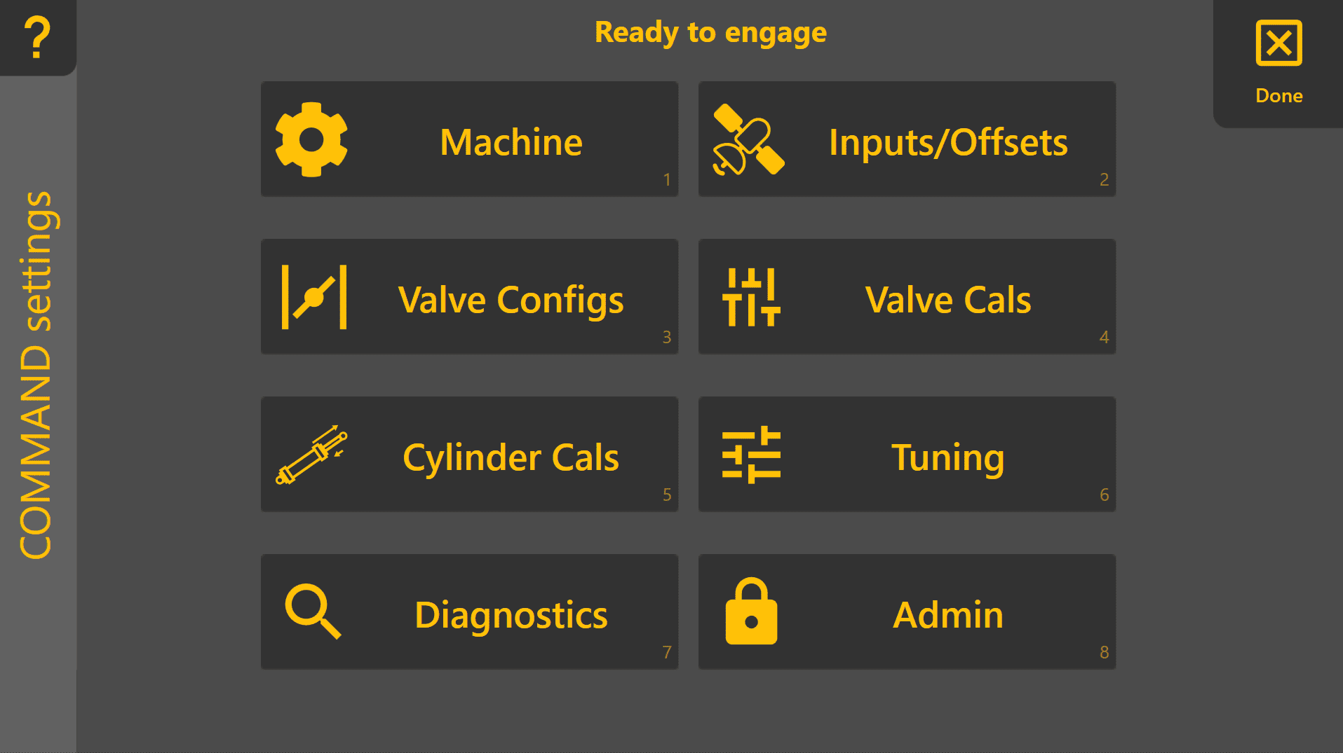
A.2 | Machine
The Machine page defines the overall machine configuration used by the COMMAND ECU.
Typical functions include:
- Selecting the machine profile
- Viewing ECU connection status
- Confirming the active machine configuration
This page is generally configured once during installation and rarely requires further adjustment.
See Section 3.2 for commissioning instructions.
A.3 | Inputs & Offsets
The Inputs & Offsets page configures the positioning sensors connected to the system.
Typical settings include:
- GNSS receiver selection
- Receiver offsets
- Implement geometry
- IMU configuration
- Position source assignment
These settings determine how the system calculates the position of the implement relative to the design surface.
Changes should only be made if hardware has been replaced, repositioned or recalibrated.
See Section 3.4 for commissioning procedures.
A.4 | Valve Configurations
The Valve Configs page defines how the COMMAND ECU interfaces with the machine's hydraulic system.
Depending on the installation, this may include:
- Hydraulic output type
- Valve interface selection
- Joystick inputs
- Automatic control enablement
- Output direction assignment
This page should only require changes when installing on a different hydraulic system or replacing major components.
See Section 3.5 for configuration instructions.
A.5 | Valve Calibration
The Valve Calibration page adjusts the hydraulic output range used during automatic control.
Calibration determines:
- The minimum output required to begin implement movement.
- The maximum output that provides full operating speed without excessive hydraulic or mechanical stress.
Correct calibration allows automatic control to operate smoothly across the full available hydraulic range.
See Section 3.6 for calibration procedures.
A.6 | Cylinder Calibration
Cylinder calibration compensates for differences in hydraulic cylinder geometry and operating speed.
The calculated cylinder ratio improves tracking performance by ensuring extension and retraction movements remain balanced.
Cylinder calibration should normally only be repeated after hydraulic repairs or changes to the implement.
See Section 3.7 for calibration procedures.
A.7 | Automatic Control
The Automatic Control page contains tuning parameters used to optimise grading performance.
Examples include:
- Acquire Sensitivity
- Tracking Sensitivity
- Look Ahead
- Additional control parameters
Most machines will perform correctly using the default values established during commissioning.
These settings should only be adjusted when fine-tuning machine performance or when requested by T3RRA Support.
See Section 3.9 for recommended tuning procedures.
A.8 | Diagnostics
The Diagnostics page provides live information from the COMMAND ECU.
Typical information includes:
- Sensor status
- GNSS information
- IMU data
- Hydraulic outputs
- ECU status
- Diagnostic messages
This page is intended primarily for fault finding and support.
T3RRA Support may request information from this page when investigating a problem.
A.9 | Tech Mode
Tech Mode exposes additional engineering and diagnostic settings intended for advanced commissioning, development and technical support.
These parameters are not required for normal machine operation and may affect system performance if modified incorrectly.
Only change Tech Mode settings when instructed by T3RRA Support.
A.10 | Administrative Functions
The Admin page contains maintenance and service functions for the COMMAND ECU.
Depending on software version, these may include:
- Software updates
- Reset or maintenance functions
- Configuration management
- Service information
Administrative functions should generally only be used during commissioning, servicing or under the guidance of T3RRA Support.