| Surface | Updated During Grading |
|---|---|
| Elevation | No (represents the original surveyed ground) |
| Design | No (represents the desired finished surface) |
| Target | Yes (may change due to Blade Shift, Cut/Fill Limiting or other operating modes) |
| Current | Continuously (tracks the live implement position) |
| As Applied Elevation | Yes (records the surface produced during grading) |
| As Applied Cut/Fill | Yes (records remaining cut and fill after grading progress) |
**Operator Tip:** Think of the surface layers as answering five different questions: Elevation — What does the ground look like today? Design — What do I want it to look like when I'm finished? Target — Where should the implement be right now? Current — Where is the implement right now? As Applied — What have I actually built so far?
Once you understand how these surface layers interact, the operation of **Automatic Control**, **Blade Control Modes**, **Blade Shift** and the other features described throughout this chapter becomes much easier to understand. # 6.2 | Automatic Blade Control **Automatic Blade Control** is the process **Level COMMAND** uses to guide the implement towards the required target position while grading. Once **Automatic Control** is engaged, **Level COMMAND** continually monitors the implement position, compares it with the required target position and sends control commands to the **COMMAND** ECU. The **COMMAND** ECU then operates the configured hydraulic outputs to move the implement as required. This process repeats continuously while **Automatic Control** remains engaged. ### Control Overview During normal operation, **Level COMMAND** continually performs the following control process: 1. Determine the current implement position. 2. Determine the required target position. 3. Compare the current position with the target position. 4. Calculate the current control error. 5. Send the required control command to the **COMMAND** ECU. 6. Measure the new implement position. 7. Repeat the process as the machine moves. This continuous feedback allows **Level COMMAND** to respond to changing terrain and maintain accurate control throughout the grading operation. ### Closed-Loop Control **Automatic Blade Control** is a closed-loop control system. Rather than commanding the implement to move once and assuming the correct position has been reached, **Level COMMAND** continually measures the implement position and updates hydraulic commands until the implement is tracking the target position correctly. This continuous feedback allows the system to compensate for changing ground conditions and maintain accurate grading performance. ### What Determines the Target Position? The target position is derived from the loaded design together with any active operator settings. Depending on the current grading task, the target position may be influenced by: - Design surface - Blade Shift - Dynamic Cut Limiting - Dynamic Fill Limiting Because of this, the target position may not always be identical to the final design surface at that moment. However, the objective remains the same: to guide the implement smoothly towards the intended finished surface. ### Hydraulic Response Hydraulic systems require a small amount of time to respond to control commands. As a result, the implement does not move instantly when the target position changes. Instead, **Level COMMAND** continuously monitors implement position and adjusts hydraulic output as the machine moves. This produces smooth, stable grading while allowing the implement to progressively converge on the target position. Later in this chapter, **Look Ahead** is introduced as one method used to further improve tracking performance by anticipating changes in terrain. ### When the Implement Is Far from Target The amount of hydraulic correction applied depends on how far the implement is from the target position. When close to the target, **COMMAND** makes small corrections to accurately maintain grade. When further from the target, larger corrections may be applied to return the implement more quickly. If the implement moves beyond the configured operating range, automatic movement may be suspended until the operator manually returns the implement closer to the working surface. ### Operator Responsibility **Automatic Control** assists with implement positioning, but the operator remains responsible for machine operation. The operator must still: - Choose the travel path. - Manage material movement. - Maintain safe travel speed. - Monitor cut/fill behaviour. - Watch for obstacles, people and changing ground conditions. - Disengage **Automatic Control** if machine behaviour is unexpected.**Level COMMAND** can guide the implement towards the target position, but it does not determine the overall earthmoving strategy. Efficient grading still depends on good operator judgement and planning.
Continue to **6.3 | Blade Control Modes** to learn how **Level COMMAND** determines the target position beneath the blade for different grading situations. # 6.3 | Blade Control Modes **Blade Control Modes** determine how **Level COMMAND** interprets the design surface beneath the blade when calculating the required target position. Different grading situations benefit from different control strategies. Some modes prioritise accurately following the design, while others minimise overcutting or improve performance around sudden changes in terrain. Selecting the appropriate Blade Control Mode can improve grading efficiency, reduce rework and produce a more consistent finished surface. The available Blade Control Modes are described below. ### Classic [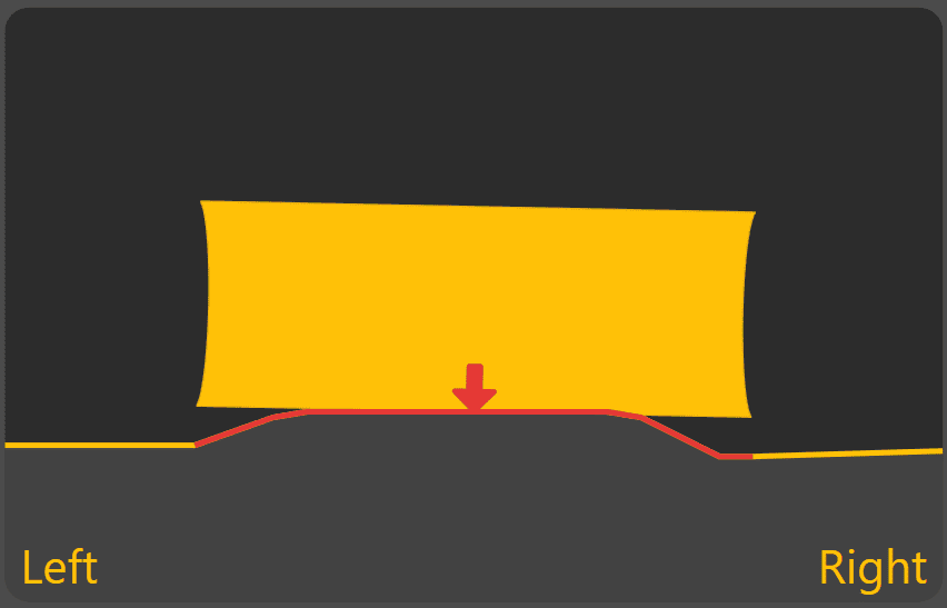](https://docs.t3rra.com/uploads/images/gallery/2026-06/q3RtKA6Vhv9PwpFE-image.png) **Classic** uses the design elevation directly beneath the centre of the blade as the target position. For Height & X-Slope applications, cross-slope is calculated using the design elevations beneath the left and right edges of the blade. This mode follows the design exactly but may overcut when crossing sudden changes in terrain, such as ditch centres or sharp breaklines. **Typical applications include:** - General grading on smooth surfaces. - Areas with gradual changes in terrain. ### Average [](https://docs.t3rra.com/uploads/images/gallery/2026-06/XJnaN6ZyClaFk23c-image.png) **Average** determines the overall trend of the design surface beneath the blade and positions the blade to follow that average profile. This produces smooth grading performance across broad, continuous surfaces and reduces sensitivity to small variations in the design. **Typical applications include:** - Broadacre landforming. - Large paddocks. - Surfaces with gradual, continuous grades. ### Average On Top [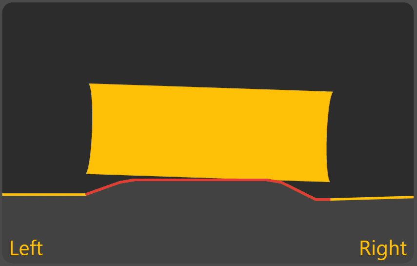](https://docs.t3rra.com/uploads/images/gallery/2026-06/YMPFR9y811P3U8Ep-image.png) **Average On Top** uses the same averaging method as **Average**, but positions the blade to avoid cutting below the design surface. This helps prevent overcutting while maintaining smooth grading performance. **Typical applications include:** - Finishing passes. - Projects where preserving the design surface is more important than maximising material removal. - Areas where overcutting must be avoided. ### Snap Fit [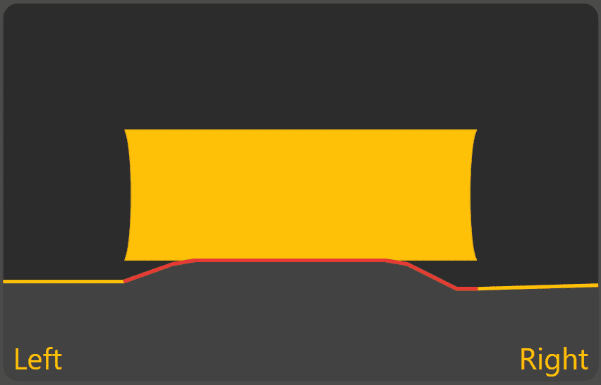](https://docs.t3rra.com/uploads/images/gallery/2026-06/Q1u4T3iWr4qA17yq-image.png) **Snap Fit** determines the blade position that best matches the design while avoiding unnecessary overcutting. When crossing abrupt changes in terrain, such as breaklines or drain batters, the blade rapidly transitions between adjacent design surfaces rather than averaging across them. This allows sharp design features to be maintained while reducing unnecessary passes. **Typical applications include:** - Drain construction. - Batters. - Breaklines. - Designs containing abrupt changes in grade. ### Single Point [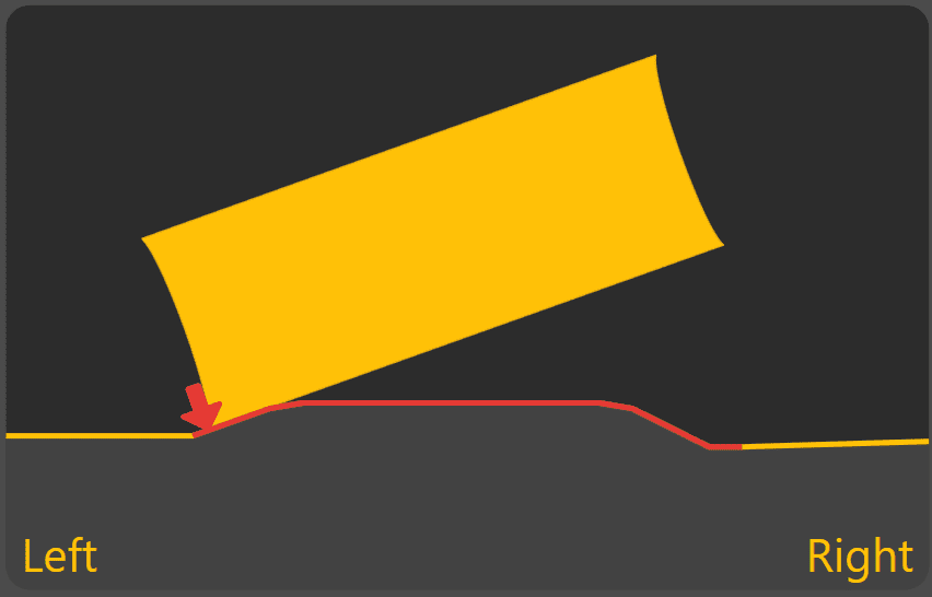](https://docs.t3rra.com/uploads/images/gallery/2026-06/KHSh9XxgpP917gt1-image.png) **Single Point** controls a single selected point on the blade rather than considering the full blade width. The selected control point is maintained on the design surface even though other parts of the blade may be above or below the design. This mode is particularly useful for constructing features where one point of the blade must accurately follow the design. **Typical applications include:** - V-drains. - Channels. - Working against existing edges. - Precision grading using one side of the blade. When **Single Point** is active, the **Swap Ctrl** button is displayed in the Back View. This allows the active control point to be quickly swapped between the left and right sides of the blade when changing travel direction. ## Choosing a Blade Control Mode No single Blade Control Mode is ideal for every grading task. Broad, continuous grading generally benefits from **Average** or **Average On Top**, while projects containing drains, batters or sharp terrain changes are often better suited to **Snap Fit** or **Single Point**. Operators should select the mode that best matches the design being constructed and the type of grading being performed. Continue to **6.4 | Blade Shift & Material Control** to learn how the target position can be temporarily adjusted during grading without modifying the underlying design. # 6.4 | Blade Shift & Target Adjustment **Blade Shift** allows the operator to temporarily adjust the Target Position during grading. This provides a quick method of making small grading adjustments to suit changing site conditions without changing the project itself.**Blade Shift changes the current Target—not the Design.** Remove the applied shift at any time to return Automatic Control to the original design surface. If large Blade Shift values become necessary, verify the project alignment and consider performing **Zero** instead.
To access the Blade Shift controls from the Apply View: [](https://docs.t3rra.com/uploads/images/gallery/2026-06/jdJ7aPFb0dL7kNGT-image.png) **Press Blade Shift.** [](https://docs.t3rra.com/uploads/images/gallery/2026-06/74TgIUkRyCaW1uXd-image.png) #### [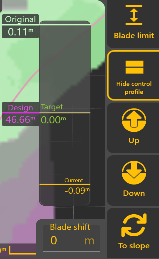](https://docs.t3rra.com/uploads/images/gallery/2025-10/jWRnJkGMLwE6RLwJ-image.png) ### Understanding the Control Profile The **Control Profile** provides a live cross-sectional view of the current grading state. It allows the operator to see how the original ground, Design, Target Position and current implement position relate to one another during **Automatic Control**. The Control Profile displays four key references: #### Original The original surveyed ground surface before grading began, shown relative to the Design. #### Design The intended finished surface. This remains fixed throughout the project and represents the final grading objective. #### Target The position currently being tracked by **Automatic Control**. Normally, the Target matches the Design. However, **Blade Shift** or **Dynamic Cut & Fill Limiting** may temporarily adjust the Target during grading. #### Current The current implement position relative to the Design. As **Automatic Control** operates, the Current position should progressively move towards the Target. ### [](https://docs.t3rra.com/uploads/images/gallery/2026-06/MG8RP10Mpsf8H8OH-image.png)Blade Shift The **Up** and **Down** buttons temporarily raise or lower the Target by the configured **Blade Shift Increment**. Multiple adjustments can be applied as required, and the current Blade Shift value is displayed within the **Blade Shift** window. Selecting the displayed value allows a specific offset to be entered directly. ### Dynamic Cut & Fill Limiting [](https://docs.t3rra.com/uploads/images/gallery/2026-06/5QNIparU1eiZEGRE-image.png)**Dynamic Cut & Fill Limiting** temporarily restricts how much material **Automatic Control** attempts to remove or place during a single pass. Rather than immediately targeting the finished Design, **Level COMMAND** calculates a temporary Target Position that respects the configured Cut or Fill Limit. As grading progresses, the Target automatically moves towards the Design until the finished surface is achieved. [](https://docs.t3rra.com/uploads/images/gallery/2026-06/hMvtO5HvXsy72yOf-image.png)Dynamic Cut & Fill Limiting is useful for: - Removing material over multiple controlled passes. - Reducing machine load. - Preventing excessive cutting or filling in a single pass. - Improving control on difficult ground. ### [](https://docs.t3rra.com/uploads/images/gallery/2026-06/G8n3SH6xjqIo88hQ-image.png)Manual X-Slope Adjustment Machines equipped with **Height & X-Slope** control can temporarily adjust the target cross-slope. Select **To Slope** to switch from Blade Shift controls to X-Slope controls. ### [](https://docs.t3rra.com/uploads/images/gallery/2026-06/sAjhmI6RPZrrI4UG-image.png) When **X-Slope Auto** is enabled, **Level COMMAND** automatically follows the Design cross-slope. When **Auto** is disabled, the operator may manually adjust the target cross-slope using the **Left** and **Right** controls or enter a specific value directly. Select **To Shift** to return to the Blade Shift controls. ### Blade Shift Increment [](https://docs.t3rra.com/uploads/images/gallery/2026-06/VqQ89Qc0hnMKD0n4-image.png)The amount applied by each press of the **Up** or **Down** buttons is determined by the configured **Blade Shift Increment**. Likewise, manual X-Slope adjustments use the configured **X-Slope Shift Increment**. To change the Blade Shift Increment, from the Apply View press: **More → Blade Shift Settings** Smaller increments provide finer control, while larger increments allow quicker adjustments during grading. Typical **Blade Shift Increment** values are:| Units | Recommended Increment |
|---|---|
| Metres | 0.01–0.02 m |
| Inches | 0.4–0.8 in |
| Feet | 0.03–0.06 ft |
**Operator Tip:** Use **Blade Shift** to make temporary grading adjustments as conditions change throughout the day. If large Blade Shift values become necessary to maintain the desired grade, verify the project alignment and consider performing **Zero** again rather than continuing to increase the applied offset.
Continue to **6.5 | Position Quality & GNSS Validation** to understand how **Level COMMAND** validates positioning information before Automatic Control is allowed to operate. # 6.5 | Reliable Positioning The accuracy of **Automatic Control** depends directly on the quality of the positioning information received from the GNSS receivers. Every control decision made by **Level COMMAND** begins with a measured implement position. If that position is inaccurate, the calculated **Target Position**, **Current Error** and hydraulic commands will also become inaccurate. ### Why Position Quality Matters [](https://docs.t3rra.com/uploads/images/gallery/2026-06/WxhL46VDQfQgpGBl-image.png)Throughout this manual, **Automatic Control** has been described as continually comparing the **Current Position** with the **Target Position**. This comparison is only meaningful if the **Current Position** accurately represents the true location of the implement. Poor positioning can result in: - Incorrect cut or fill values. - Unnecessary hydraulic movement. - Reduced grading accuracy. - Poor finished surfaces. - Unstable **Automatic Control**. Although **Level COMMAND** continuously validates incoming positioning information, it cannot improve the accuracy of incorrect or poor-quality GNSS measurements. ### Position Validation Before **Automatic Control** is permitted to operate, **Level COMMAND** verifies that the received positioning information meets the configured operating requirements. Typical validation checks include: - Receiver communication. - IMU availability (where fitted). - Position update rate. - RTK positioning quality. - Position stability. If one or more validation requirements are not satisfied, **COMMAND Status** reports the reason and **Automatic Control** may be prevented from engaging or may disengage until valid positioning information is restored. ### Monitoring GNSS Operation [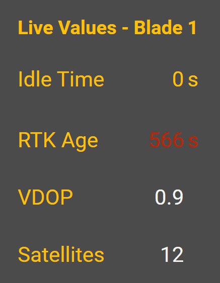](https://docs.t3rra.com/uploads/images/gallery/2026-06/XR9cOw6DbZ3Mdi1i-image.png)During normal operation, **COMMAND Status** provides the primary indication of GNSS-related operating conditions. Depending on the situation, **COMMAND Status** may report messages such as: - **Waiting for RTK** before **Automatic Control** can be engaged. - **Loss of RTK** if RTK positioning is lost during operation. - **Unstable GPS or IMU** if the measured position or orientation becomes unreliable. Additional live GNSS information can be viewed from: **More → COMMAND Settings → GPS Thresholds** This page displays live receiver information including RTK status, Satellite Count, VDOP and RTK Age, allowing the operator or dealer to confirm that the GNSS system is operating as expected. ### When Further Investigation May Be Required [](https://docs.t3rra.com/uploads/images/gallery/2026-07/Oi51jiB3GPYSuTrA-image.png) If positioning quality remains poor, the cause often lies outside **Level COMMAND** itself. Further investigation may be required if: - RTK cannot be achieved. - RTK is repeatedly lost during operation. - Surveyed elevations appear inconsistent. - **Automatic Control** repeatedly disengages due to positioning quality. - **COMMAND Status** repeatedly reports GNSS or IMU warnings. [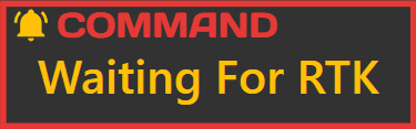](https://docs.t3rra.com/uploads/images/gallery/2026-06/Kzbbj8nQzHJC4Xz4-image.png)Depending on the installation, this may require checking: - GNSS receiver configuration. - Base station operation. - Radio or correction link performance. - Receiver antenna installation. - Machine wiring and communication. These components provide the positioning information used by **Level COMMAND** and should be operating correctly before investigating **Automatic Control** performance. ### Good Operating Practice For the best grading performance: - Wait until RTK positioning has been achieved before beginning work. - Verify **COMMAND Status** displays **Ready to Engage**. - Investigate repeated RTK loss before continuing work. - Confirm receiver and base station configuration if persistent positioning issues occur.**Operator Tip:** If grading accuracy suddenly deteriorates, verify the quality of the GNSS solution before adjusting control settings or recalibrating the machine. Many apparent control problems are ultimately caused by poor positioning rather than incorrect Automatic Control settings.
Continue to **6.6 | Automatic Control Tuning** to learn how **Level COMMAND** can be optimised once reliable positioning has been established. # 6.6 | Automatic Control Tuning The quality of **Automatic Control** is determined by several systems working together. Poor grading performance is often caused by multiple small issues rather than a single fault. Rather than immediately adjusting tuning or calibration values, verify that each stage of the control process is operating correctly. [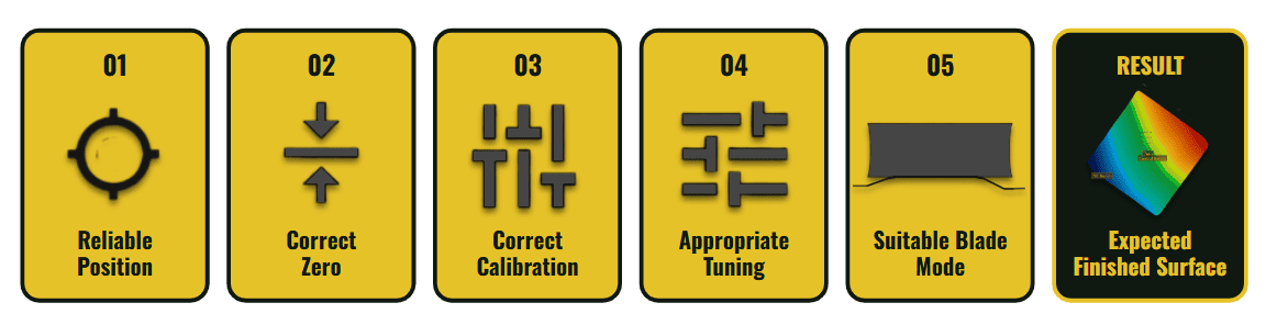](https://docs.t3rra.com/uploads/images/gallery/2026-06/xiOhnpiTfCVYqabk-image.png) The diagram above shows the recommended order for evaluating **Automatic Control** performance. Each stage provides the foundation for the next. Problems identified early in the process should be corrected before moving on to later stages.| Factor | Why It Matters |
|---|---|
| **Reliable Position** | Accurate GNSS positioning is the foundation of **Automatic Control**. Poor position data cannot be corrected through tuning or calibration. |
| **Correct Zero** | Zero aligns the project with the real world. An incorrect Zero causes every calculated Target Position to be offset from the intended Design. |
| **Correct Calibration** | Correct valve calibration ensures the hydraulic system begins moving at the expected output and reaches full output when required. Incorrect calibration often produces symptoms similar to poor tuning. |
| **Appropriate Tuning** | Once calibration is correct, Tracking Sensitivity fine-tunes how aggressively the implement responds to changing conditions. Small adjustments are normally sufficient. |
| **Suitable Blade Control Mode** | Selecting the appropriate Blade Control Mode allows **Level COMMAND** to interpret the Design in a way that best suits the grading task and terrain. |
| **Good Finished Surface** | When each stage is functioning correctly, **Automatic Control** can consistently produce accurate and repeatable grading results. |
**Operator Tip:** Make one adjustment at a time. Changing multiple settings together makes it difficult to determine which change improved—or degraded—control performance. Verify the effect of each adjustment before making the next.
Continue to **6.7 | Predictive Control & Look Ahead** to learn how **Level COMMAND** anticipates machine movement and compensates for hydraulic response delays. # 6.7 | Look Ahead [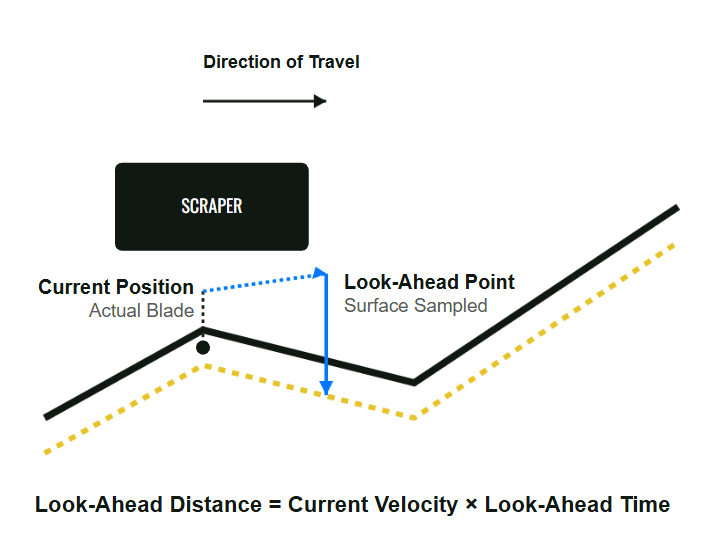](https://docs.t3rra.com/uploads/images/gallery/2026-06/64z4b3mNwZb7hRoD-image.png) Hydraulic systems require a short amount of time to respond after a control command is issued. Oil must flow, hydraulic cylinders must move and the implement must physically react before the blade reaches its new position. To compensate for this delay, **Level COMMAND** uses **Look Ahead**. Rather than waiting until the implement reaches a change in the Design, **Level COMMAND** begins commanding hydraulic movement slightly in advance so the implement reaches the correct position at the appropriate time. This predictive behaviour helps produce smoother, more accurate grading, particularly when operating at higher travel speeds or over changing terrain. ## How Look Ahead Affects Grading The amount of Look Ahead determines how early **Automatic Control** begins responding to upcoming changes in the Design. ### Too Little Look Ahead If the **Look Ahead** value is too small, the hydraulic system may respond too late. Typical symptoms include: - The implement reacts after reaching changes in the Design. - Rounded crests or delayed transitions. - Persistent tracking error. - Reduced grading accuracy at higher travel speeds. ### Too Much Look Ahead If the **Look Ahead** value is too large, the hydraulic system may respond earlier than necessary. Typical symptoms include: - The implement begins lifting or lowering too early. - Overcorrection approaching changes in terrain. - Reduced grading accuracy around abrupt transitions. ## Adjusting Look Ahead The **Look Ahead** setting can be accessed from: **More → Diagnostics/Advanced**For most machines, the default value provides good performance and should not normally require adjustment.
Changes should only be made after confirming: - Reliable RTK positioning. - Correct Zero. - Correct valve calibration. - Appropriate Tracking Sensitivity.Adjusting **Look Ahead** before these items have been verified may make diagnosing control performance more difficult.
**Operator Tip:** Treat **Look Ahead** as an advanced tuning parameter. If **Automatic Control** is performing well, leave the default setting unchanged. Adjust it only when there is a clear reason to do so and after the rest of the control system has been verified.
Continue to **6.8 | Tandem & Multi-Blade Behaviour** to understand how **Level COMMAND** manages machines with multiple control points and implements. # 6.8 | Tandem Blade Behaviour The Tandem Scraper profile allows **Level** **COMMAND** to control two trailing scrapers independently during the same grading operation. Although each scraper is controlled separately, the overall operating workflow remains almost identical to a single scraper. Most setup, calibration and operating procedures described throughout this manual apply equally to both blades. [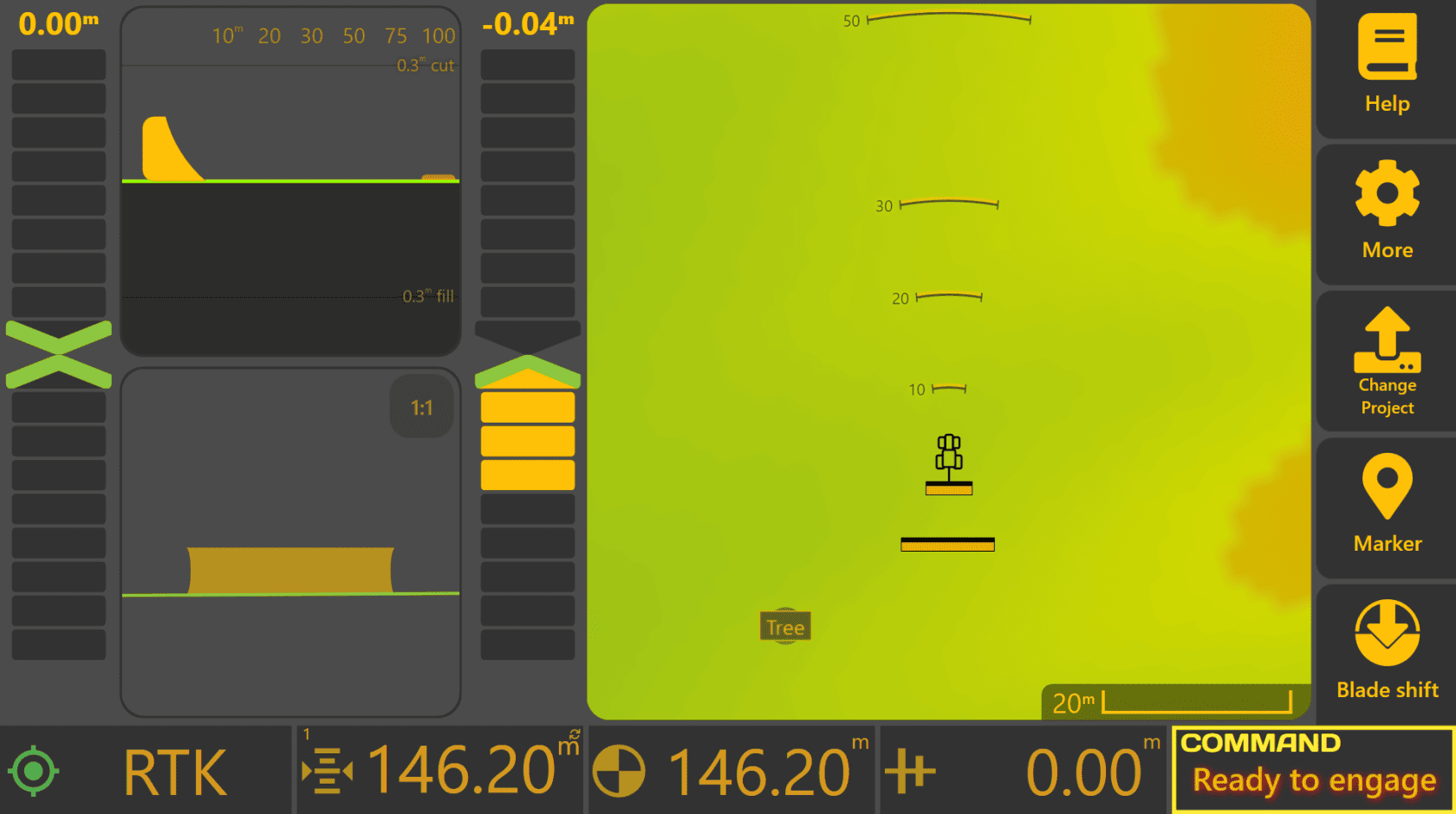](https://docs.t3rra.com/uploads/images/gallery/2026-06/H4799G0EDpHlx8bE-image.png) ### Independent Control Each scraper maintains its own control solution based on its individual position and configuration. Each scraper has independent: - GNSS receiver configuration. - Receiver offsets. - Look-Ahead calculation. - Blade Position calculation. - Automatic Control output. - Dynamic Cut & Fill Limiting. This allows each scraper to respond correctly to the terrain beneath it, even though both are working as part of the same machine. ### Shared Adjustments Some operator adjustments intentionally affect both scrapers together. For example: - Blade Shift applies the same vertical offset to both blades. - Project Zero applies to the entire machine. - The selected Blade Control Mode applies consistently across the machine profile. This keeps both scrapers working toward the same finished design while still allowing each blade to respond independently to local terrain. ### [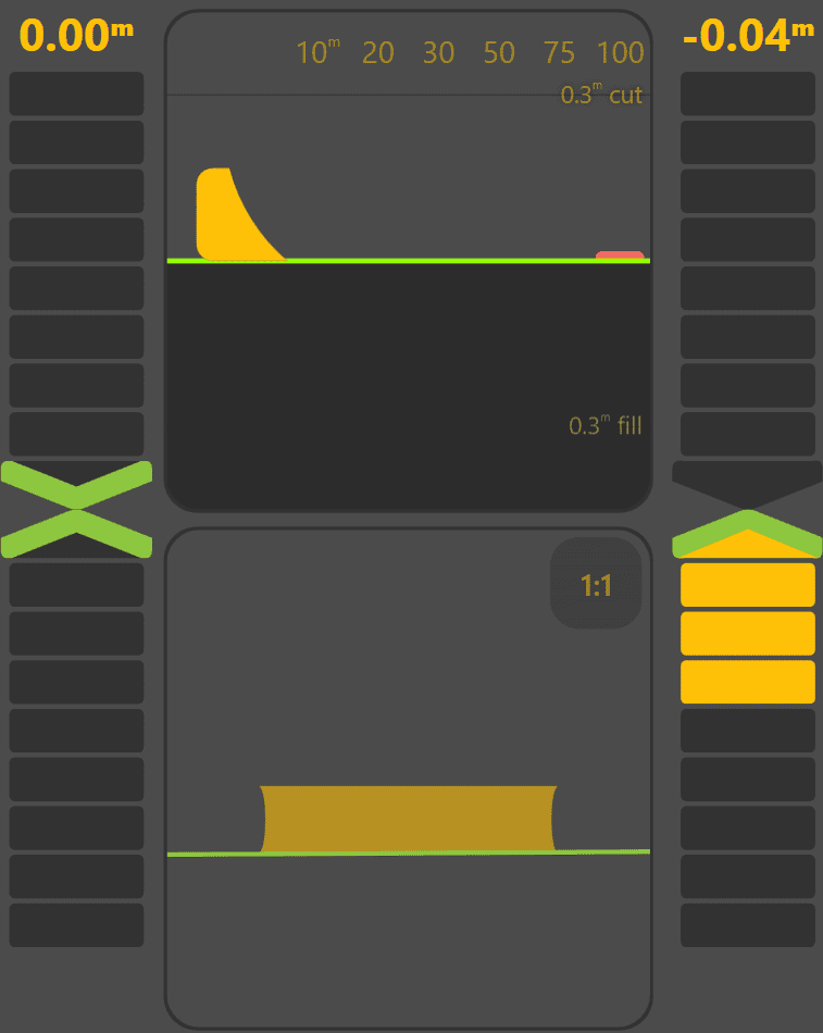](https://docs.t3rra.com/uploads/images/gallery/2026-06/lYYIxmtmsPeMDrcH-image.png)Monitoring Both Scrapers When using the Tandem Scraper profile, the Apply View displays two On-Grade Indicators—one for each scraper. *image.png* Each indicator displays the grading error for its respective scraper, allowing the operator to quickly confirm that both blades are tracking their Target Positions correctly. Additional widgets are also available for monitoring the individual position and performance of each scraper where required. ### Commissioning a Tandem Machine Commissioning a Tandem Scraper follows the same process as commissioning a single scraper. Each scraper should be configured and calibrated individually, including: - GNSS configuration. - Receiver offsets. - Hydraulic calibration. - Automatic Control tuning. Once both scrapers have been configured, they operate together as a single machine profile.**Operator Tip:** Treat each scraper as an independent Automatic Control system. Although both blades work toward the same finished surface, each one must be correctly configured and calibrated to achieve the best overall grading performance.
**Chapter Summary:** Throughout this chapter you've seen how **Level COMMAND** interprets the design surface, calculates the Target Position and continuously adjusts the implement to achieve a smooth, accurate finished result. Understanding these Automatic Control concepts makes it easier to interpret system behaviour and recognise how positioning, calibration, tuning and machine configuration influence grading performance. The next chapter builds on this foundation by covering the more detailed aspects of machine setup, calibration and advanced system configuration.