5 | Operational Workflows
This chapter introduces the workflows used throughout normal grading operations. It explains how to create and manage projects, collect survey data, import designs, organise project markers and prepare work for Automatic Control.
- 5.1 | Apply View Overview
- 5.2 | Apply View Layout
- 5.3 | Widget Customisation
- 5.4 | Plane Projects & Surface Creation
- 5.5 | Pre-designed Projects & Data
- 5.6 | Surveying & Field Data Collection
- 5.7 | Markers & Benchmarks
- 5.8 | Choosing a Zeroing Method
5.1 | Apply View Overview
The Apply View is the primary operating screen used while grading. It combines machine guidance, design information, Automatic Control status and operator controls into a single workspace, allowing the operator to monitor grading progress and operate Level COMMAND without leaving the main screen.
Unlike the Quick Start chapter, which focuses on getting the machine operating, this section explains the purpose of each area of the Apply View and how they work together during normal operation.
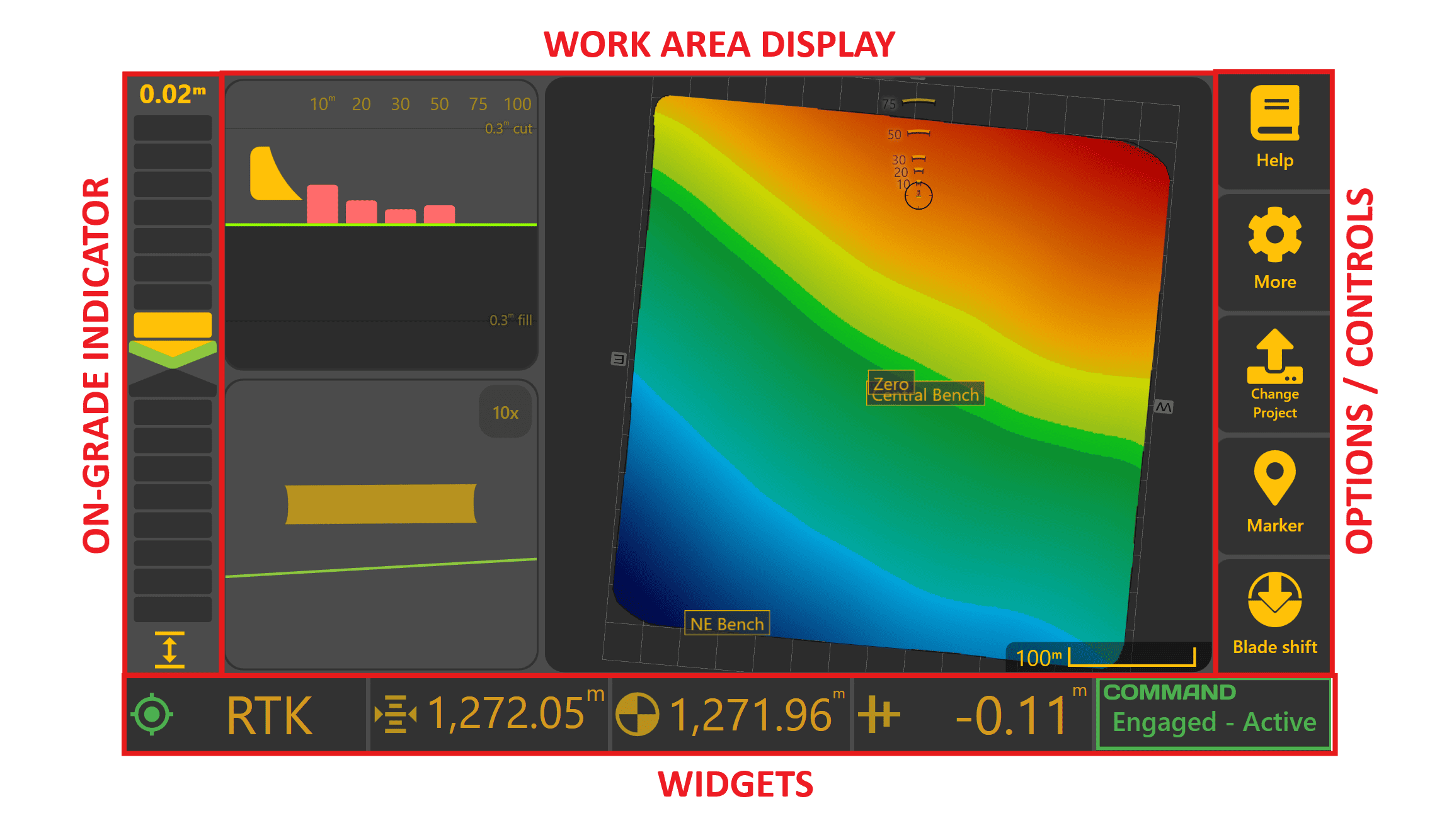
The Apply View can be divided into four main areas:
- On-Grade Indicator
- Work Area Display
- Operator Controls
- Status Widgets
Additional project information is available through the More menu when required.
On-Grade Indicator

 The On-Grade Indicator provides the quickest indication of whether the implement is currently above, below or on the target surface. During grading, it is typically the primary guidance reference used by the operator for monitoring height error.
The numerical value displayed above the indicator shows the current error between the implement position and the target surface.
- Arrow pointing up – the implement needs to be raised.
- Arrow pointing down – the implement needs to be lowered.
- Both arrows green with no coloured bars – the implement is within the configured deadband and is considered on grade.
As grading error increases, additional indicator segments illuminate to provide an immediate visual indication of how far the implement is from the target.
Deadband
A small deadband surrounds the target elevation to prevent the indicator continually changing state due to normal GNSS measurement variation.
By default, the deadband is ±1.5 cm. While within this range the indicator will appear on grade, although the numerical error value continues to display the true measured error.
 Blade Shift

Blade Shift temporarily offsets the current target above or below the design surface without changing the design itself.
When Blade Shift is active, a Blade Shift icon is displayed beneath the indicator. This reminds the operator that the current target has been intentionally offset from the design surface.
 Cut/Fill Limiting

When Dynamic Cut or Fill Limiting is enabled, the indicator normally displays the error between the implement and the limited target rather than the final design surface.
Pressing/tapping the indicator toggles between:
- Current tracking target (limited).
- Error to the final design surface.
When displaying error to the design surface, the indicator uses the current cut/fill colour scheme to show the full design error.
Work Area Display
The centre of the Apply View displays the current work area together with optional guidance views that assist the operator while grading.
The display consists of one primary viewing area and two secondary viewing areas. Each area can independently display:
- Map
- Side View
- Back View
Operators can arrange these views to suit different tasks using the Layout settings.
Examples include:
- Full-screen Map
- Map + Side View
- Map + Back View
- Side View + Back View
- Map + Side View + Back View
The purpose of each view is described below.
Map
 The Map displays the current project together with the machine position.
During operation it is primarily used to:
- Monitor grading progress
- Identify remaining cut and fill
- Plan efficient travel paths
- Review completed work
Selecting any point on the map displays information for that location, including surface values where available.
The displayed colours and surface layers are configurable using the Appearance settings described later in this chapter.
Side View
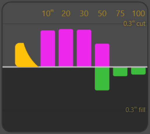 The Side View provides a preview of the terrain ahead of the implement based on the current direction of travel. Upcoming cuts and fills are displayed relative to the design surface, allowing the operator to anticipate changing ground conditions before reaching them.
As grading progresses, the preview updates using the current As Applied Cut/Fill surface, allowing the operator to see grading progress in front of the machine.
Back View
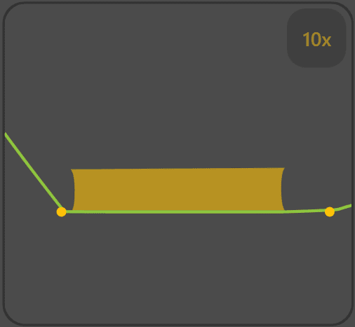
The Back View displays a cross-section across the blade width.
This view is particularly useful when grading dual-height and Height + X-Slope applications, allowing the operator to compare the measured surface against the design across the entire implement width.
The displayed vertical scale can be adjusted by selecting the scale indicator.
Where project linework intersects the displayed cross-section, intersection markers are also shown to assist with alignment.
Operator Controls
The right-hand toolbar provides quick access to the functions most commonly used while grading.
Depending on the current project type, some buttons may change to provide direct access to project-specific functions such as Plane selection or Project selection.
Detailed operation of these functions is covered throughout this manual.
The primary controls include:
| Control | Purpose |
|---|---|
| Help | Opens the Level COMMAND manual. |
| More | Accesses additional settings, diagnostics and project functions. |
| Project / Plane | Changes projects or manages Plane surfaces depending on the current project type. |
| Marker | Creates project markers and benchmarks. |
| Blade Shift | Temporarily offsets the target above or below the design surface without modifying the design itself. |
Status Widgets
The widgets along the bottom of the Apply View display continuously updated operating information while grading.
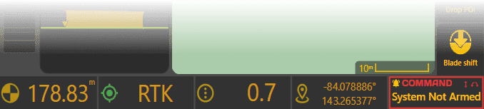
Widgets can display a wide variety of operating information, including:
- GNSS status
- Speed
- Elevation
- Current Error
- Hydraulic information
- Position
- Cut/Fill values
The COMMAND Status widget is always displayed at the bottom-right of the Apply View and cannot be removed. It continuously reports the current operating state of the COMMAND ECU, including readiness, engagement state and any operator actions or faults requiring attention.
Widget selection and layout are fully configurable and are described in 5.3 | Widget Customisation.
Operator Tip: Becoming familiar with the Apply View allows you to monitor machine performance, anticipate changes in terrain and access the controls required for efficient grading without leaving the main operating screen.
Once you are familiar with the Apply View, continue to 5.2 | Apply View Layout, which explains how the display can be customised to suit different operating preferences and grading tasks.
5.2 | Apply View Layout
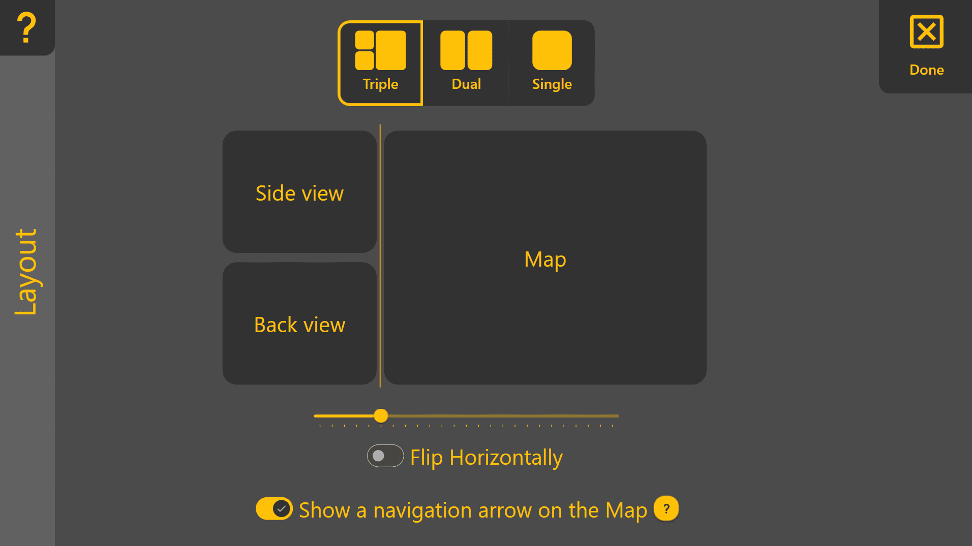
The Layout page allows the Apply View to be customised to suit different machines, grading tasks and operator preferences.
To open the Layout page from the Apply View, press:
More → Layout
Choosing a Layout

Three layout modes are available:
- Triple – Displays one main viewing area with two secondary viewing areas.
- Dual – Displays one main viewing area with one secondary viewing area.
- Single – Displays a single view across the entire screen.
Select the desired layout by pressing Triple, Dual or Single at the top of the page.
Selecting Display Views
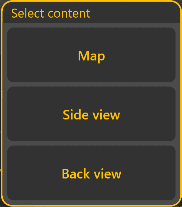
Each display area can independently display one of the following:
- Map
- Side View
- Back View
Simply press any display area shown on the Layout page to choose which view it will display.
This allows the Apply View to be configured for different operating tasks. Common examples include:
- Full-screen Map for maximum work area visibility.
- Map + Side View to preview upcoming cut and fill.
- Map + Back View to monitor cross-fall.
- Map + Side View + Back View to view all guidance information simultaneously.
Layout Options
Additional options are available when using the Dual or Triple layouts.
Split Position
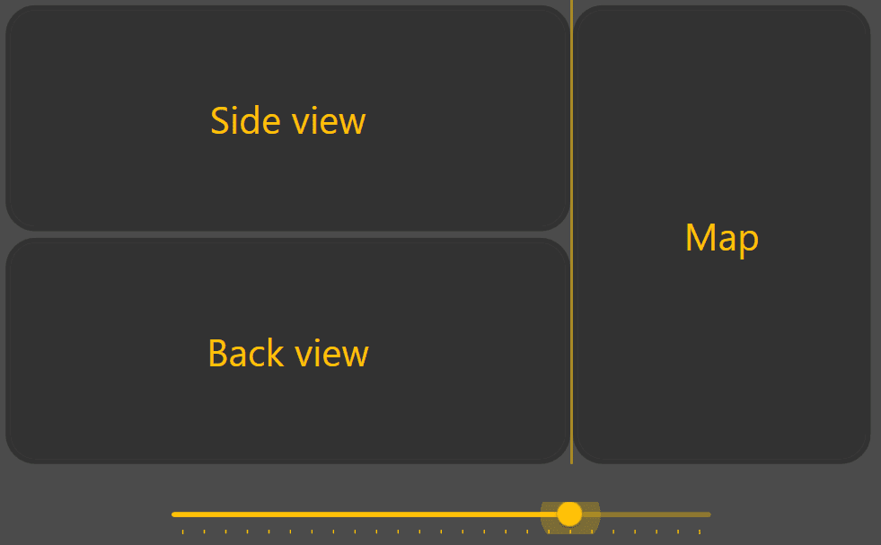 Use the slider to adjust how much screen space is allocated to the main viewing area and the secondary viewing areas.
Increasing the size of the main viewing area provides a larger Map display, while increasing the secondary viewing areas makes the Side View or Back View easier to monitor.
Flip Horizontally
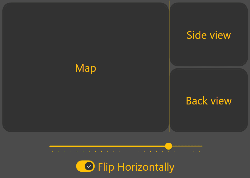
Enable Flip Horizontally to swap the positions of the main and secondary viewing areas.
This can improve visibility depending on display mounting position or operator preference.
Navigation Arrow

The arrow points towards the centre of the project surface and displays the approximate direction and distance to the work area. This can be particularly useful when travelling between fields or locating a project after loading it.
Continue to 5.3 | Widget Customisation to configure the information displayed along the bottom of the Apply View.
5.3 | Widget Customisation
The widgets along the bottom of the Apply View provide quick access to important machine, GNSS and grading information while operating Level COMMAND.
Almost every widget can be replaced with another value, allowing the display to be customised to suit different operators, machine configurations or grading tasks.
The COMMAND Status widget at the far right of the Apply View is fixed and cannot be changed.
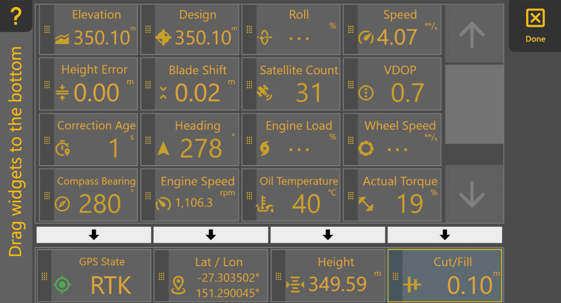
Opening Widget Settings
To customise the displayed widgets:
- Press and hold any configurable widget along the bottom of the Apply View.
- The Widget Settings page will open.
The upper section displays all available widgets, while the lower section shows the widgets currently displayed on the Apply View.
Changing Displayed Widgets
Widgets can be replaced using either of the following methods.
Drag and Drop
Press and hold any available widget, then drag it onto one of the widget positions along the bottom of the screen. When released, the selected widget replaces the existing widget.
Arrow Selection
Alternatively:
- Select the desired widget from the upper list.
- Press the arrow above the widget position you wish to replace.
This method can be easier when operating with gloves or on smaller displays.
Reordering Widgets
Widgets may also be rearranged by dragging them between positions along the bottom row.
When finished, press Done to return to the Apply View.
Changing Measurement Units
Many widgets display measurements using configurable units.
To change measurement units:
More → Units
The available units depend on the information being displayed.
Available Widgets
| Widget | Description |
|---|---|
| Elevation | Current surveyed ground elevation at the implement location. |
| Design | Design elevation at the current location. |
| Height | Current implement height. |
| Cut/Fill | Amount of cut or fill required at the current location. |
| Height Error | Difference between the current implement height and the target height. Persistent error may indicate incorrect valve calibration or that the implement cannot physically reach the target. |
| Blade Shift | Displays the current Blade Shift offset applied to the target surface. This widget displays the active offset only; Blade Shift is adjusted using the Blade Shift control on the Apply View. |
| Speed | Current machine speed. |
| Heading | Current direction of travel relative to north. |
| Latitude / Longitude | Current GNSS position. |
| Roll (X-Slope) | Current implement roll angle. |
| Target Roll | Target roll angle defined by the design surface. |
| Roll Error | Difference between the measured roll angle and the target roll angle. Useful when monitoring X-Slope performance. |
| GNSS Status | Current GNSS positioning quality. RTK provides the highest positioning accuracy. |
| Satellite Count | Number of satellites currently being tracked. Some receivers may report fewer satellites than are actually contributing to the position solution. |
| VDOP | Vertical Dilution of Precision. Lower values generally indicate better vertical positioning accuracy. |
| Correction Age | Time since the last RTK correction was received. Lower values indicate a healthier correction link. |
| Actual Torque* | Engine torque currently being produced. |
| Demanded Torque* | Engine torque currently being requested. |
| Engine Load* | Current engine load as a percentage. |
| Engine Speed* | Current engine speed (RPM). |
| Oil Temperature* | Hydraulic oil temperature. |
| Compass Bearing* | Vehicle heading reported by the machine. |
| Wheel Slip* | Estimated wheel slip percentage. Higher values indicate reduced traction. |
*Available only when supported by the connected machine CAN network.
Operator Tip: Configure the widgets you check most often so they can be read with a quick glance while grading. Some operators keep GNSS Status, Height, Cut/Fill and Current Blade Shift permanently visible, then customise the remaining widget to suit the current task.
Continue to 5.4 | Surface & Map Visualisation to configure the appearance of the Work Area Display within the Apply View.
5.4 | Plane Projects & Surface Creation
Plane Projects allow simple design surfaces to be created without first surveying the entire work area. They are commonly used for creating flat pads, graded surfaces, drain batters and other simple earthworks. Each Plane Project can contain up to four individual Plane surfaces, making it easy to switch between different work areas or design surfaces without creating additional projects.
Creating a Plane Project
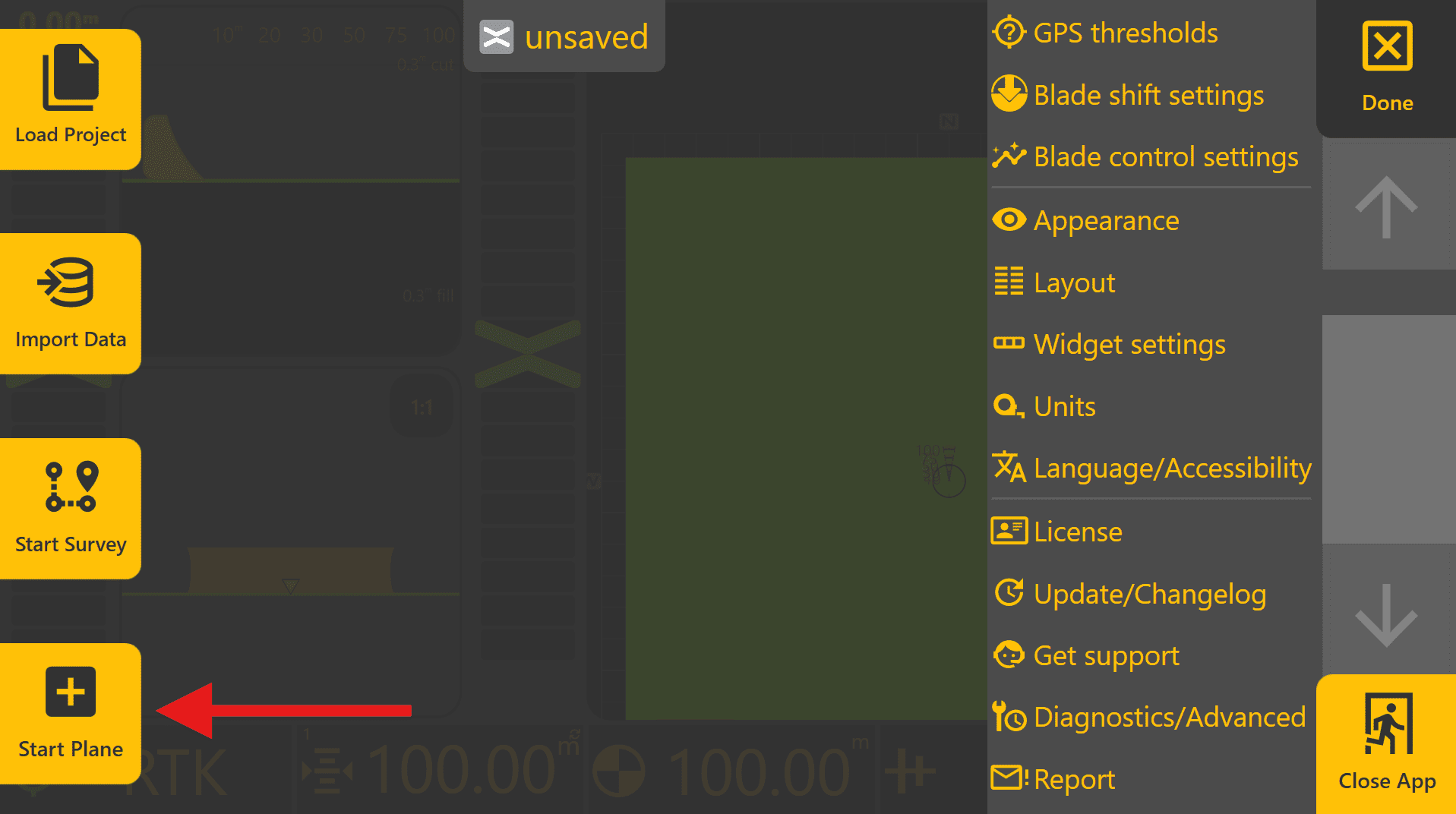
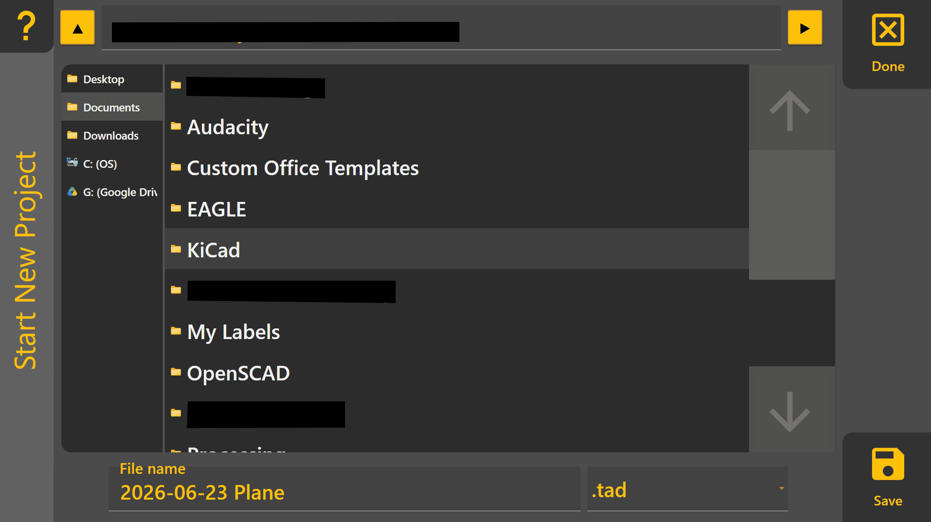


Selecting and Managing Plane Surfaces
Press Planes on the right side of the Apply View to display the available Plane slots.
Up to four Plane surfaces can be stored within a single Plane Project. Each Plane can have its own:
- Name
- Size
- Origin Point
- Primary Slope
- Secondary Slope
- Elevation Offset
To create a new Plane, select any unused slot labelled Create and the Plane Editor will open on the right side of the screen.
To switch between existing Planes, select the desired Plane from the list. The active Plane is indicated by a yellow outline.
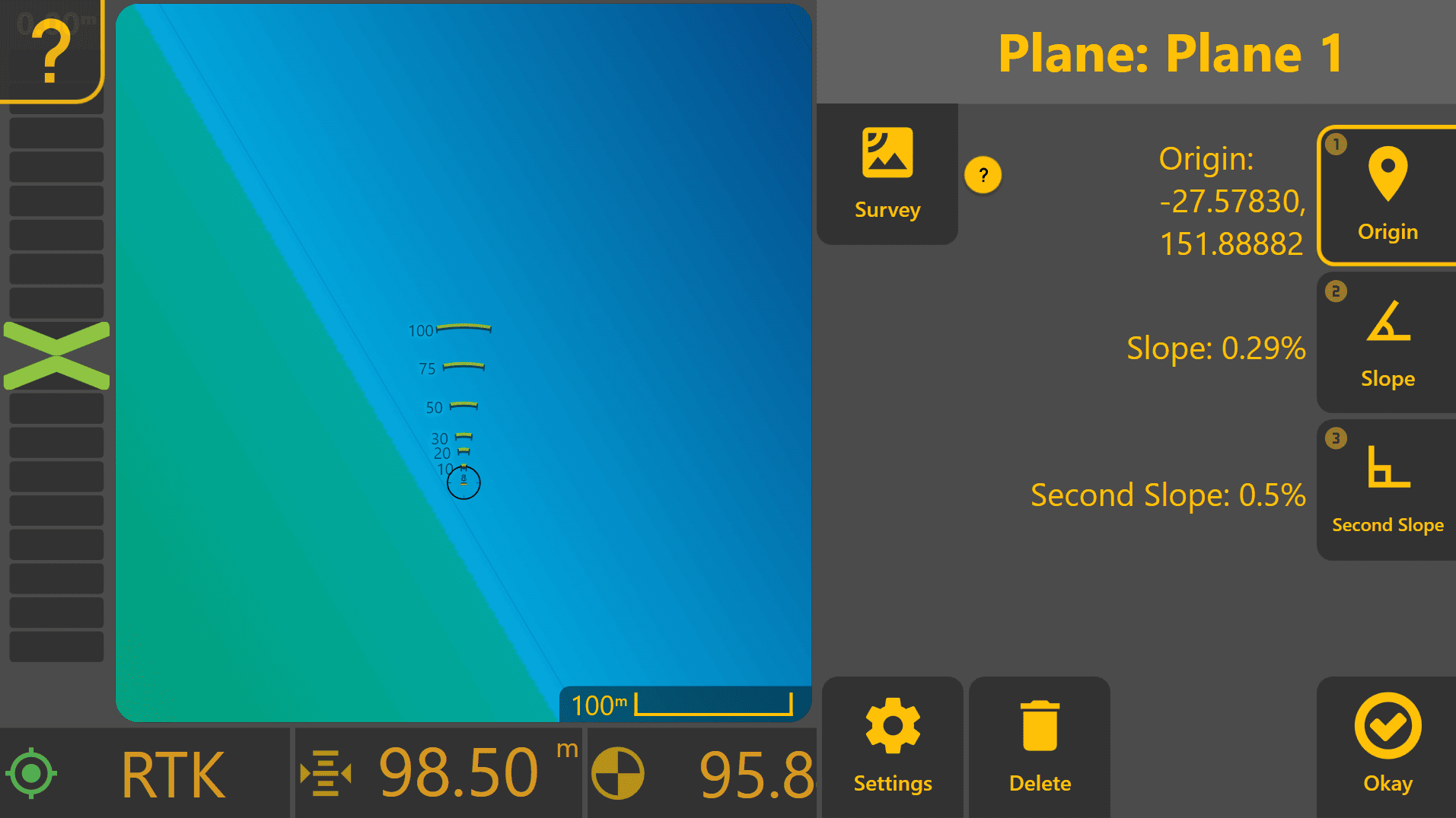
To edit an existing Plane, select it and then select it again to open the Plane Editor. The Plane Editor is used to define and modify all Plane properties, including origin, slopes and survey-based Plane generation.
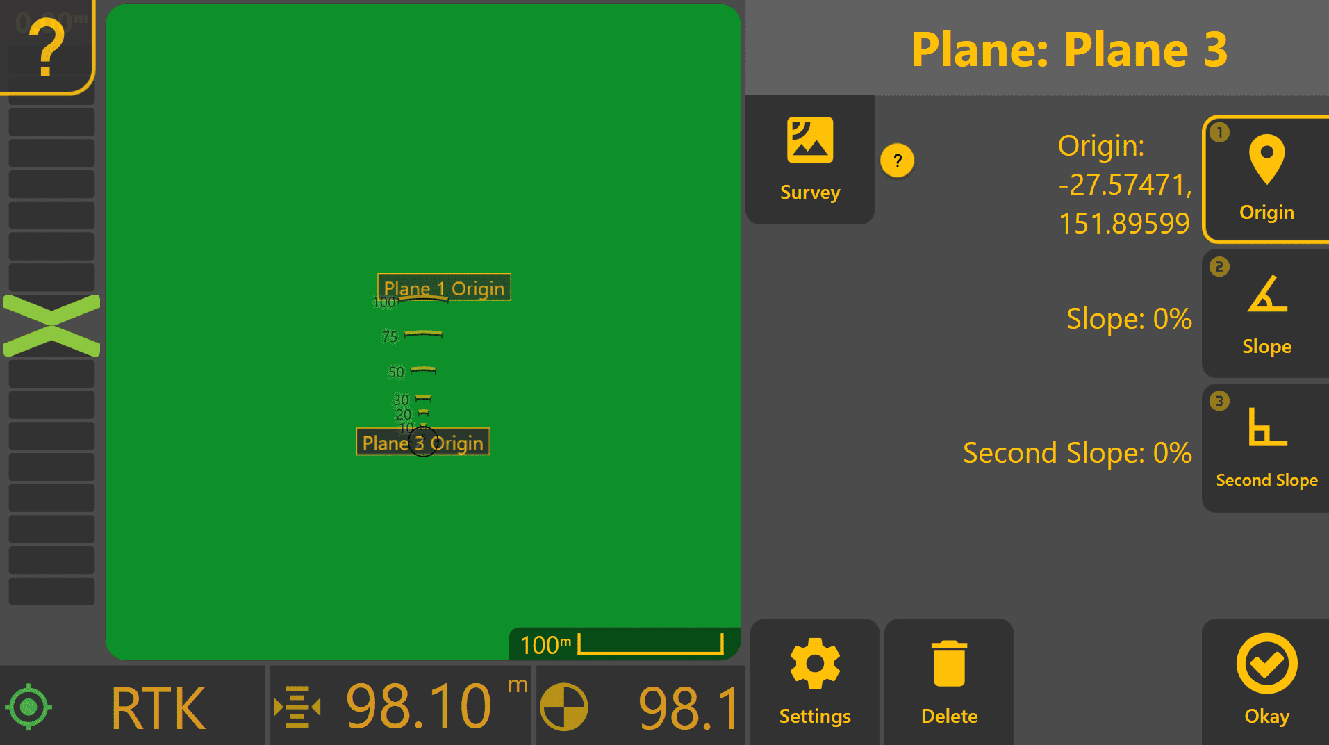
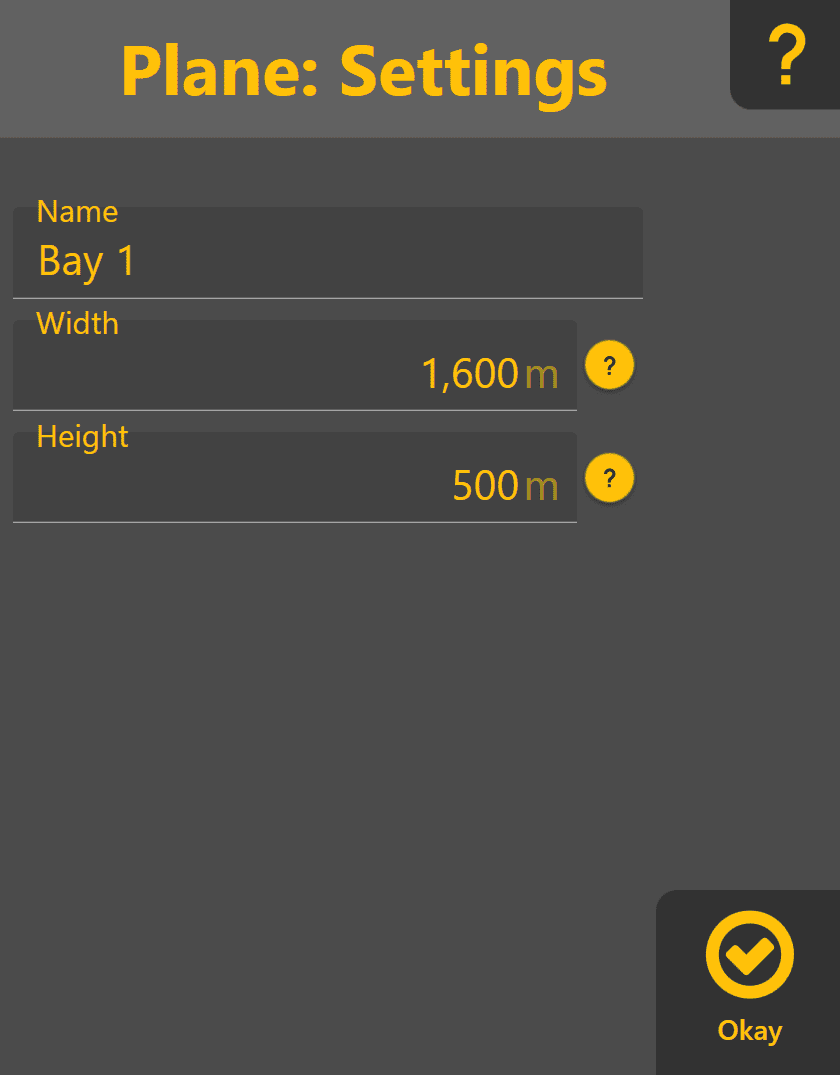
Plane Settings
Press Settings within the Plane Editor to configure the Plane name and dimensions. Assigning a meaningful Name makes it easier to identify different work areas within a project.
Plane Width and Height determine the visible extent of the generated Plane surface. These values may be adjusted at any time without affecting the calculated grade of the Plane.
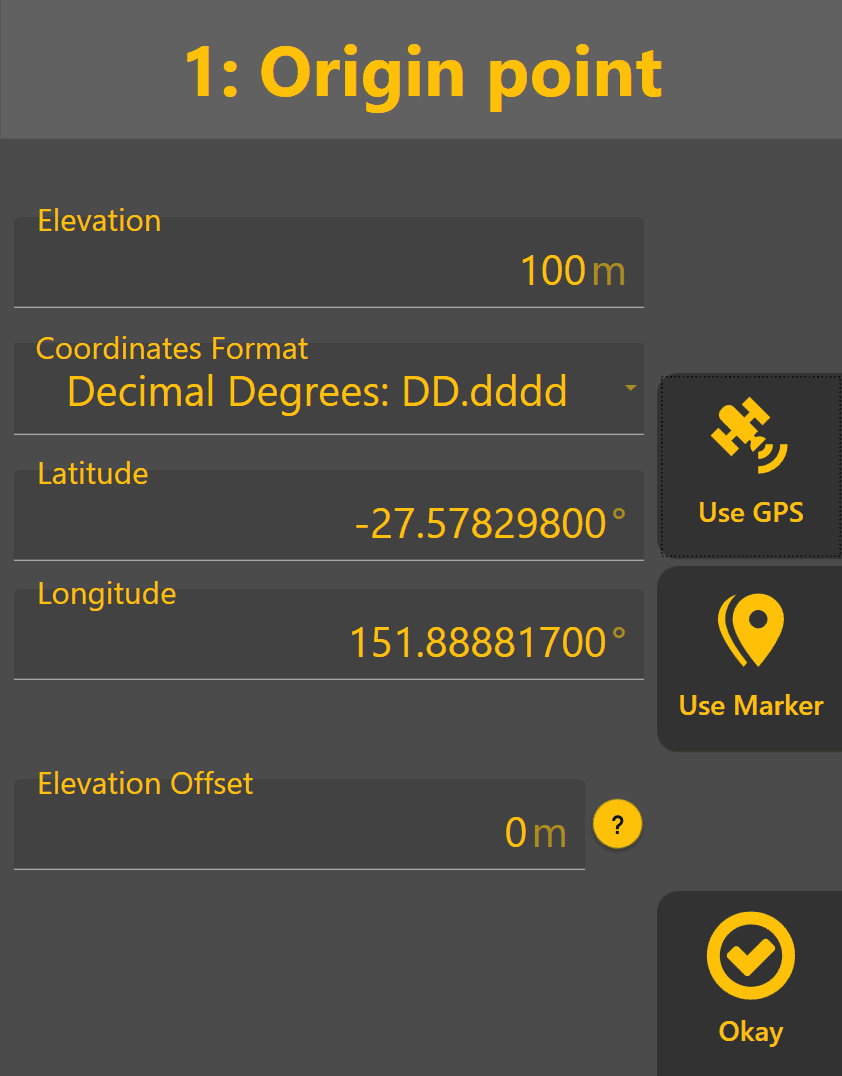
Defining the Origin Point
The Origin Point is the reference position used to define the Plane elevation and calculate all Plane slopes. It can be thought of as the anchor point of the Plane.
Press Origin within the Plane Editor to define or modify the Origin Point.
The Origin may be defined using:
- Use GPS – Sets the Origin to the current implement position and elevation.
- Use Marker – Uses an existing marker as the Origin Point.
- Manual Coordinates – Allows Latitude, Longitude and Elevation values to be entered directly.
Manual coordinate entry is commonly used when creating a Plane from a surveyed benchmark or known control point.
Once the Origin has been defined, press Okay to return to the Plane Editor. A newly created Plane will initially be flat, with the Origin positioned at the centre of the surface.
Elevation Offset
Elevation Offset allows the entire Plane to be shifted vertically without changing the underlying Plane definition. This is commonly used to quickly raise or lower a design surface when filling, trimming or removing surface irregularities while preserving the existing Plane slopes.
Positive values raise the Plane. Negative values lower the Plane.
Coordinate Formats
The Coordinate Format setting changes how Latitude and Longitude values are displayed. This is a display preference only and does not affect the actual position of the Plane.
Defining the Primary Slope
The Primary Slope defines the main grade direction of the Plane and determines how the surface rises or falls across the work area. Press Slope within the Plane Editor to define the Primary Slope.
The Primary Slope may be created automatically by using a second point on the desired grade surface:
-
Position the machine at the desired second point on the Plane.
-
Place the blade on the ground or at the desired design elevation.
-
Press Use GPS.
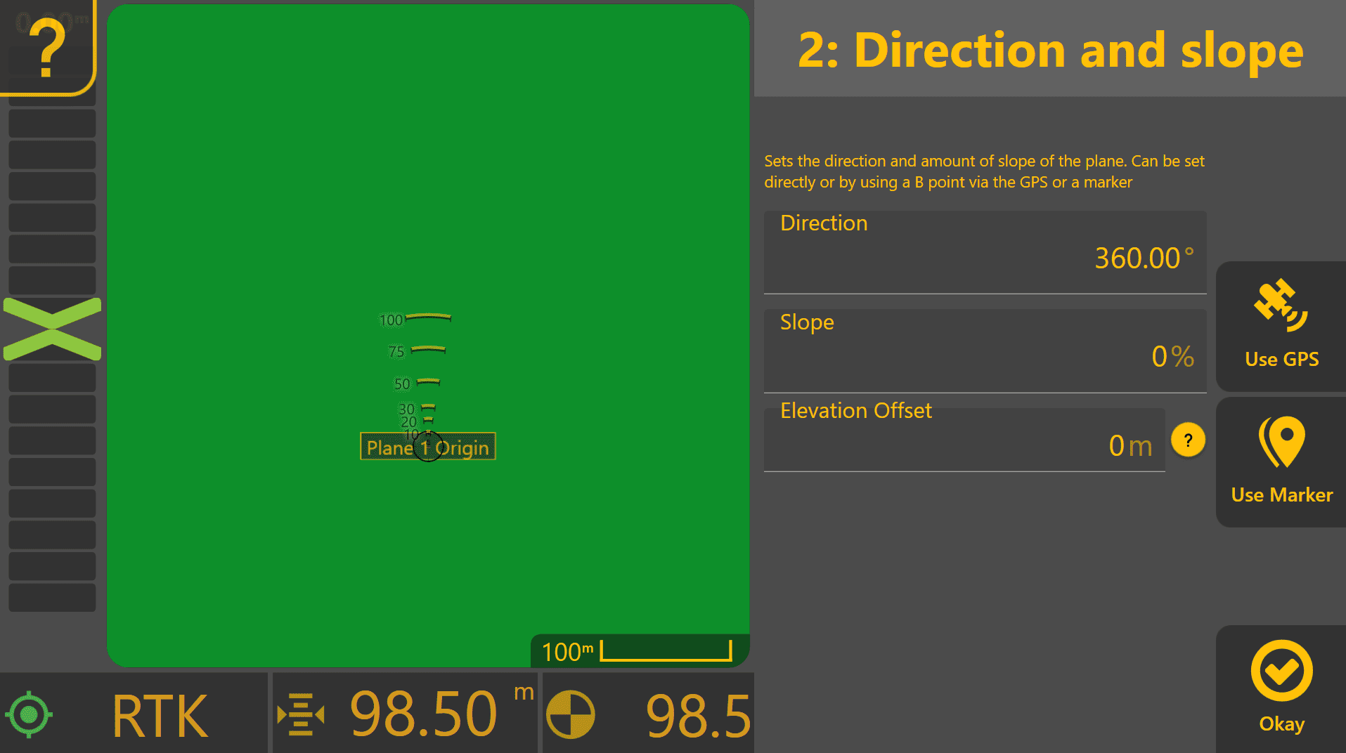
Level COMMAND will calculate the slope and direction between the Origin Point and the selected location, then update the Plane surface automatically. Alternatively, the slope percentage and direction may be entered manually if the desired grade is already known.
Once the desired slope has been defined, press Okay to return to the Plane Editor.
Direction
Direction determines the heading along which the Primary Slope is applied.
Slope
Slope determines how steeply the Plane rises or falls along the selected direction. Slope values are expressed as a percentage:
Slope (%) = 100 × Rise ÷ Run
Use GPS
Calculates the slope and direction automatically using the current implement position and the Origin Point. The calculated values may be edited afterwards if required.
Use Marker
Calculates the slope and direction using a previously created Marker and the Origin Point. The calculated values may be edited afterwards if required.
Defining the Secondary Slope
The Second Slope (X-Slope) defines the cross-fall of the Plane at right angles to the Primary Slope. This is commonly used when creating crowned surfaces, side-falls, drain batters or other surfaces requiring grade in two directions.
Press Second Slope within the Plane Editor to define the Secondary Slope. As with the Primary Slope, the Secondary Slope can be generated automatically using a second reference point:
-
Position the machine at a point representing the desired cross-fall of the Plane.
-
Place the blade on the ground or at the desired design elevation.
-
Press Use GPS.
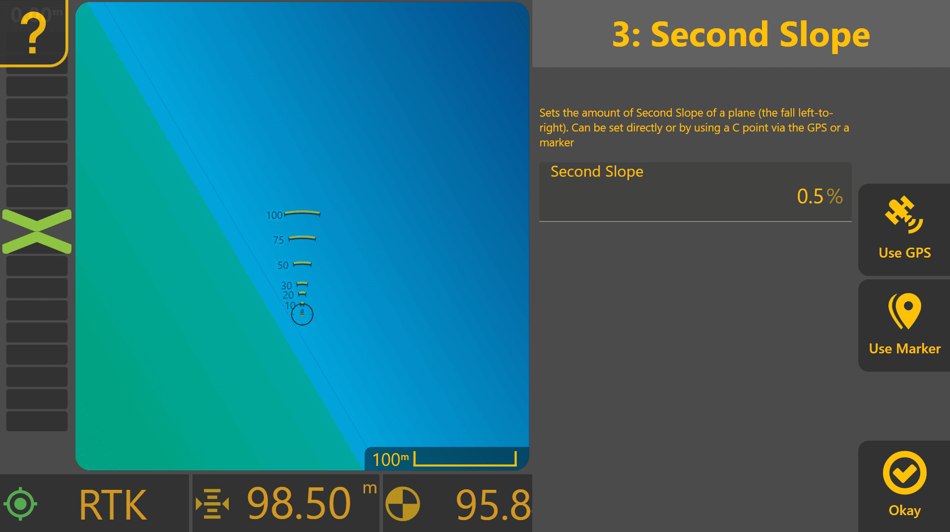
Level COMMAND will calculate the Secondary Slope relative to the Origin Point and update the Plane surface automatically. Alternatively, a known Secondary Slope percentage may be entered manually.
Unlike the Primary Slope, direction does not need to be specified because the Secondary Slope is always applied at 90 degrees to the Primary Slope.
Once the desired Secondary Slope has been defined, press Okay to return to the Plane Editor.
The final Plane surface is calculated using the Origin Point, Primary Slope and Secondary Slope together to define the overall grade of the design surface.
Surveying & Generating A Best Fit Plane

When the desired Plane slope and direction are not known, Level COMMAND can survey an area and automatically generate a best-fit Plane surface.
A best-fit Plane represents the average grade of the surveyed area by calculating the most suitable Plane from the collected survey positions and elevations.
This workflow is commonly used when:
- Levelling an existing paddock while maintaining the current fall.
- Smoothing high and low spots without significantly changing overall drainage.
- Creating a Plane surface when the desired grade has not been surveyed or designed beforehand.
- Quickly generating a reference surface for testing and machine setup.
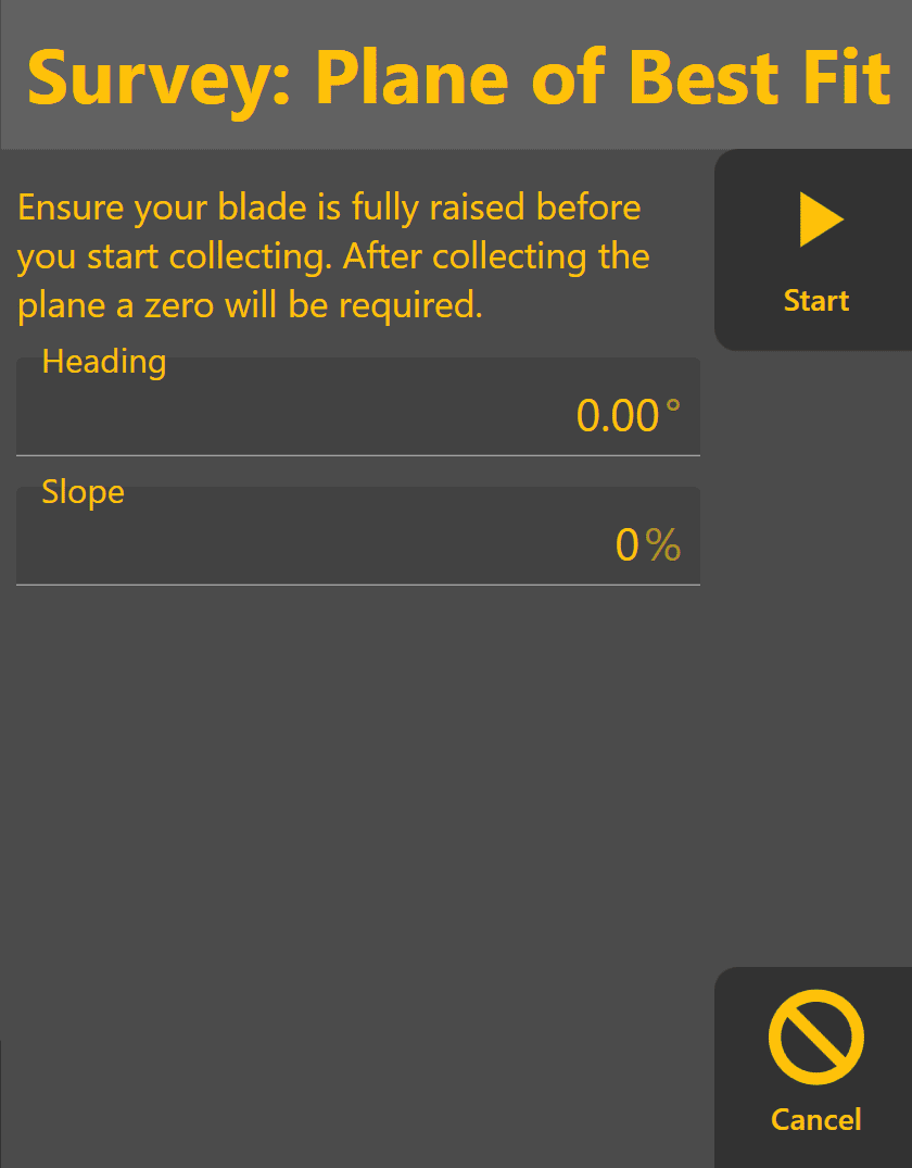
Creating a Best-Fit Plane
- Press Planes from the Apply View.
- Select an available Plane slot.
- Press Survey.
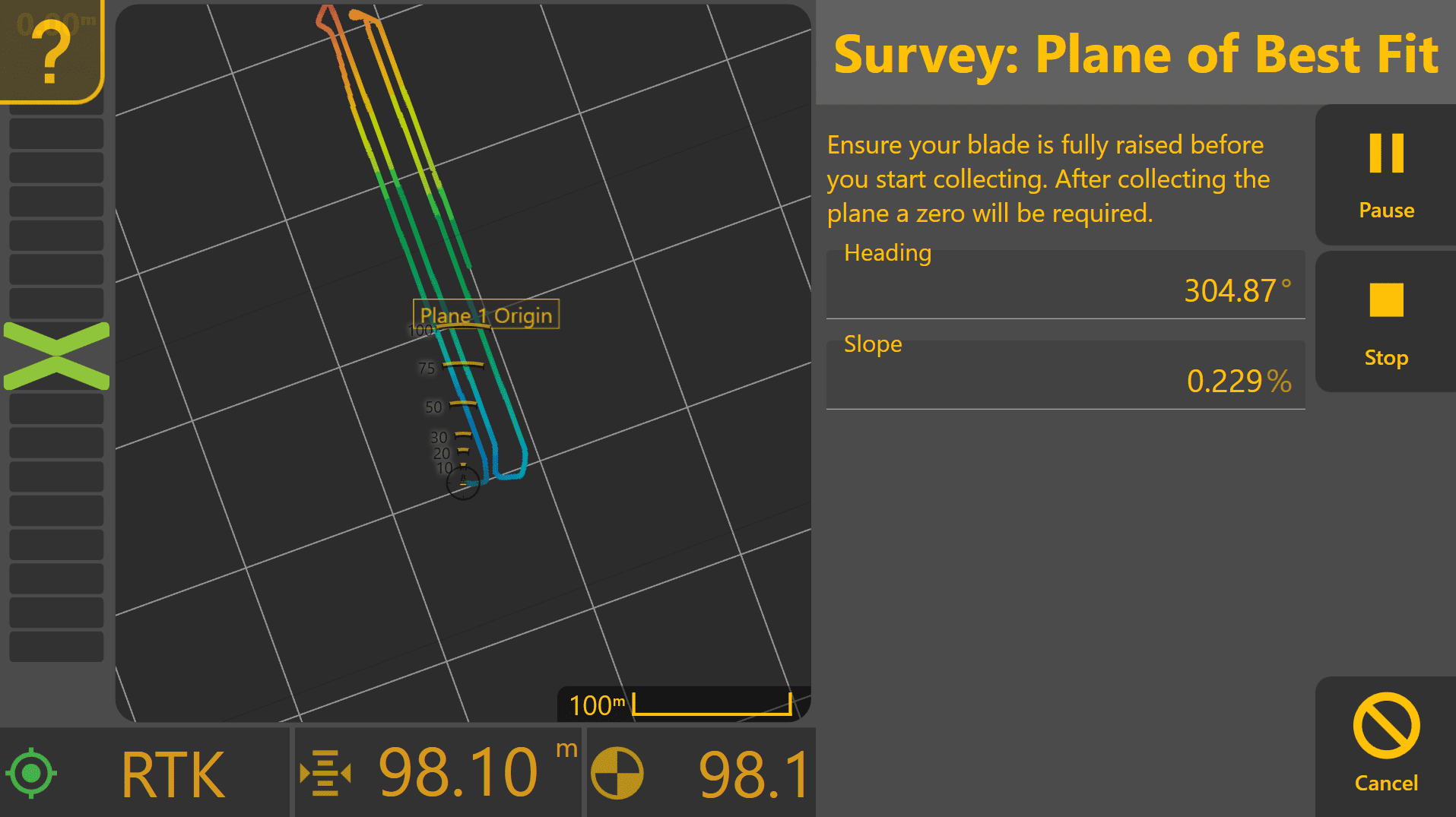
- Press Start to begin recording survey points.
- Drive throughout the area to be represented by the Plane surface.
- Press Stop once the survey is complete.
Level COMMAND will analyse the collected survey points and automatically calculate a best-fit Plane.
Once generated, the calculated Plane will be displayed and can immediately be used for Automatic Control.
Surveying Tips
For best results:
- Survey the entire area that will be worked.
- Collect points from both high and low areas.
- Avoid surveying only a small section of the work area.
- Raise the implement while surveying to avoid unintended grading. Once surveying has started, maintain a consistent implement height and avoid making manual height adjustments until the survey is complete.
As additional survey points are collected, the calculated Plane heading and slopes will generally become more stable and representative of the surveyed area.
Reviewing the Calculated Plane
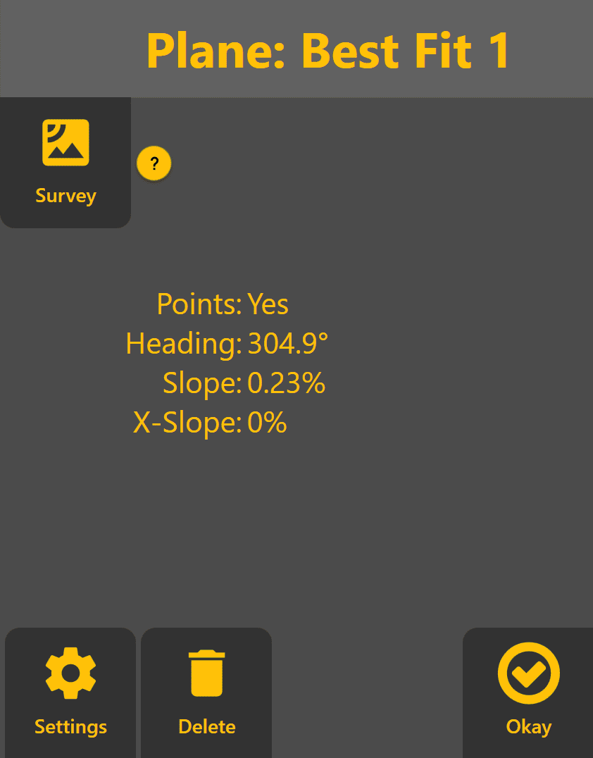
Once the Plane has been generated, selecting the Plane from the Planes menu will display the calculated:
- Heading
- Primary Slope
- Secondary Slope (X-Slope)
These values may be entered into a new plane if adjustment is required.
Additional Controls
The following controls remain available while working with a surveyed Plane:
- Settings – Modify the Plane name and dimensions.
- Delete – Remove the Plane and free the slot for reuse.
- Survey – Perform a new survey and recalculate the Plane.
- Okay – Save the Plane and return to the Apply View.
5.5 | Pre-designed Projects & Data
Pre-designed Projects allow Level COMMAND to grade using surfaces that have been created outside the application. These projects are typically prepared by a dealer, surveyor or designer before being transferred to the machine.
Compared with Plane Projects, imported projects can contain significantly more information, including surveyed terrain, finished design surfaces, boundaries, linework, markers and benchmark locations.
Preparing Design Data
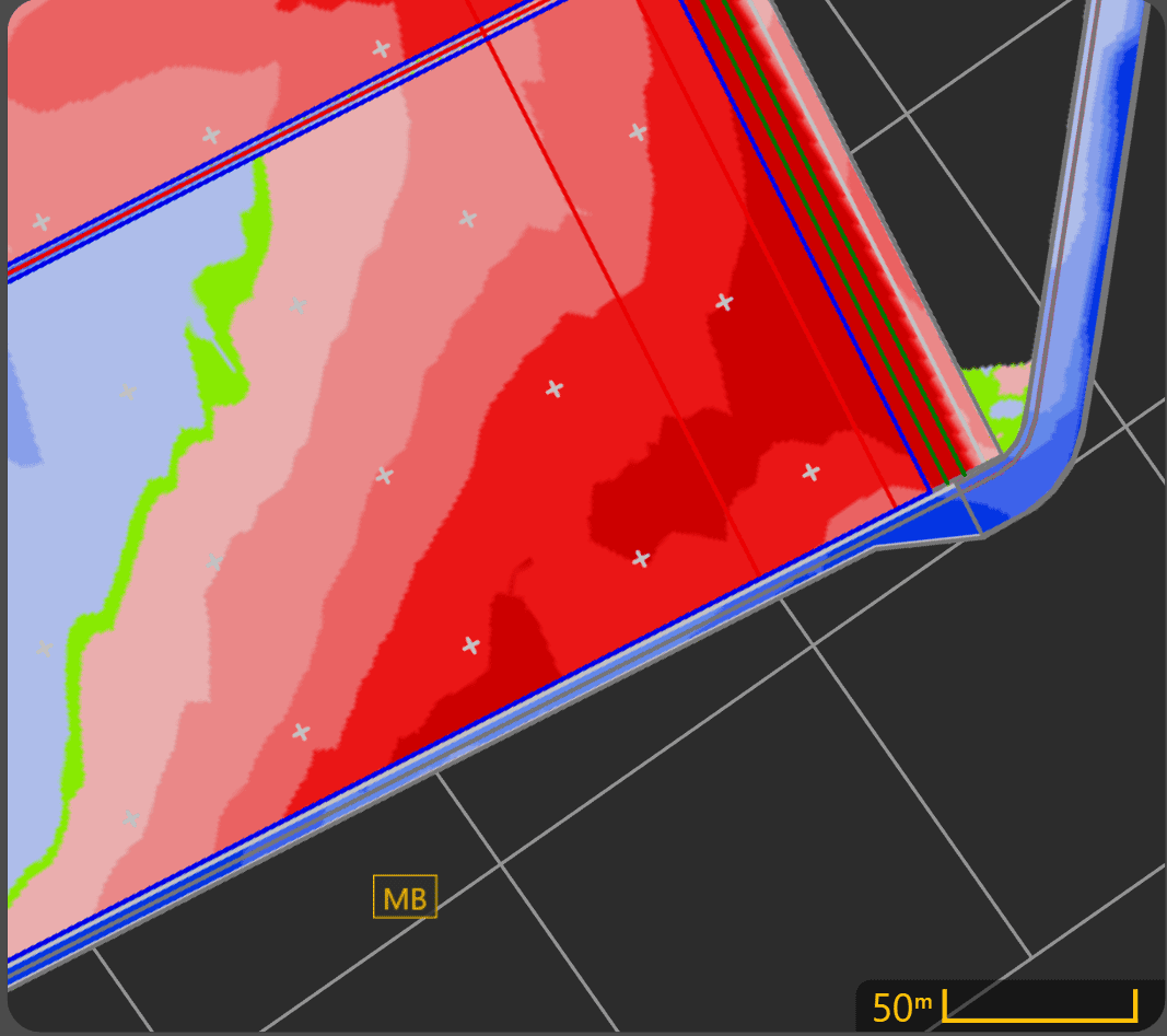
Before importing a project, verify that the supplied design includes the information required for the intended grading operation.
Where possible, imported projects should include:
- A finished design surface.
- One or more Benchmark Markers for zeroing.
- Boundaries where appropriate.
- Linework or other design features if required.
Benchmarks should be placed in locations that:
- Can be reached safely by the machine.
- Are unlikely to be disturbed during construction.
- Provide sufficient room to accurately position the implement during zeroing.
Following these practices makes future verification and re-zeroing significantly easier.
Supported File Types
At the time of writing, Level COMMAND supports importing T3RRA project files:
| File Type | Description |
|---|---|
| .tci | T3RRA project file containing one or more design surfaces and associated project data. |
Additional import formats may be supported in future software releases.
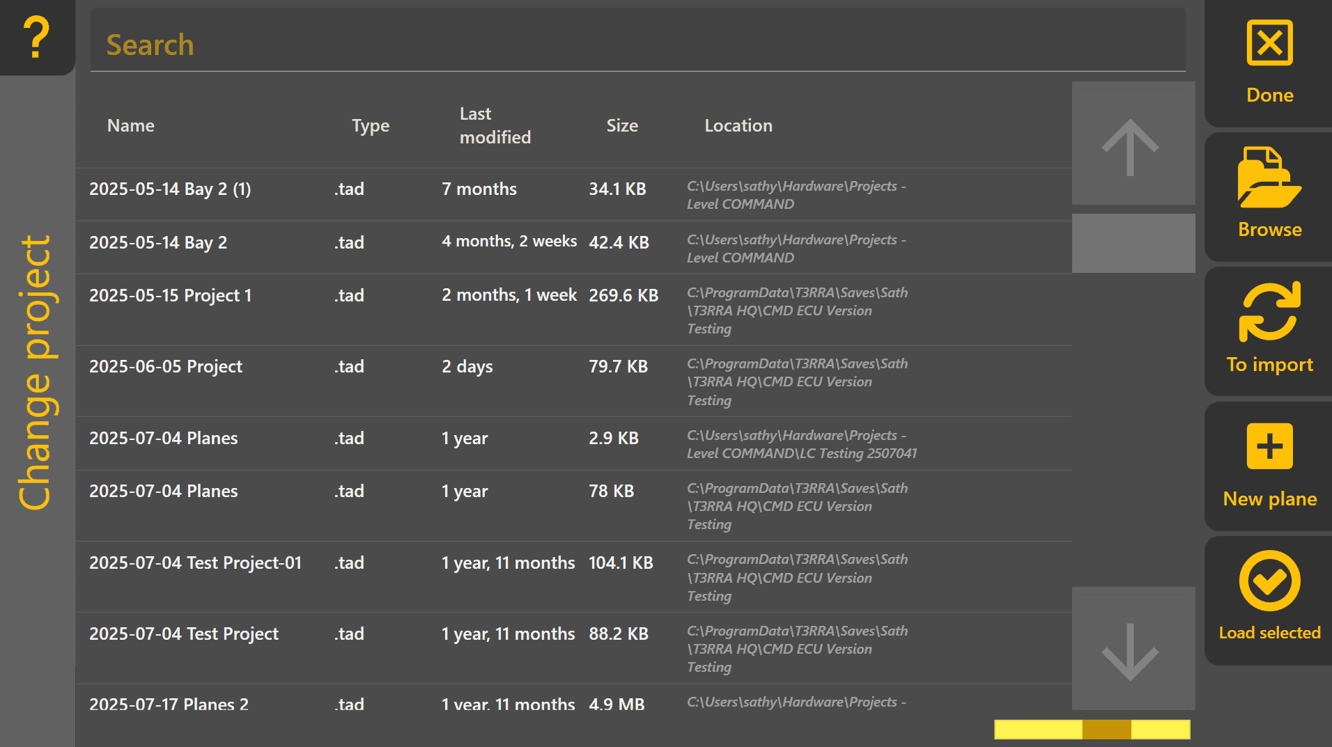
 Loading an Existing Level COMMAND Project
To load an existing Level COMMAND project:
- Press More → Load Project.
- Select the desired project.
- Press Load.
The selected project immediately becomes the active grading project.
Importing External Design Data
To import new design data into Level COMMAND:
- Press More → Import Data.
- Select the desired design file.
- Press Import Selected.
- Once complete, load the imported project if it does not open automatically.

Imported data becomes part of a Level COMMAND .tad project and can then be used like any other project.
Imported Project Features
Depending on how the project was created, imported data may include:
- Design surfaces
- Existing terrain surveys
- Benchmark Markers
- General Markers
- Boundaries
- Linework
- Additional project information
The available information depends on the design software used and the data exported.
Working with Imported Projects
Once loaded, imported projects are operated in the same way as any other project.
The operator may:
- Set Zero using a Benchmark Marker.
- Record additional surveys.
- Create new markers.
- Monitor cut and fill.
- Engage Automatic Control.
- Continue updating surveyed surfaces during grading.
Although imported projects may contain complex design information, the grading workflow remains exactly the same as described throughout this manual.
Operator Tip: If possible, review imported project data before arriving on site. Confirm that the expected design surface, benchmark locations and project features are present before beginning work. Discovering missing benchmarks or incorrect project data is far easier before the machine enters the field.
Continue to 5.6 | Surveying & Field Data Collection to learn how Level COMMAND records terrain data for design creation, project verification and future grading operations.
5.6 | Surveying & Field Data Collection
The Survey tool records terrain data for design creation, project verification and archival purposes. Surveys may be collected before grading to capture the existing ground surface, or after grading to verify completed work. The recorded data can then be exported for use in third-party design software.

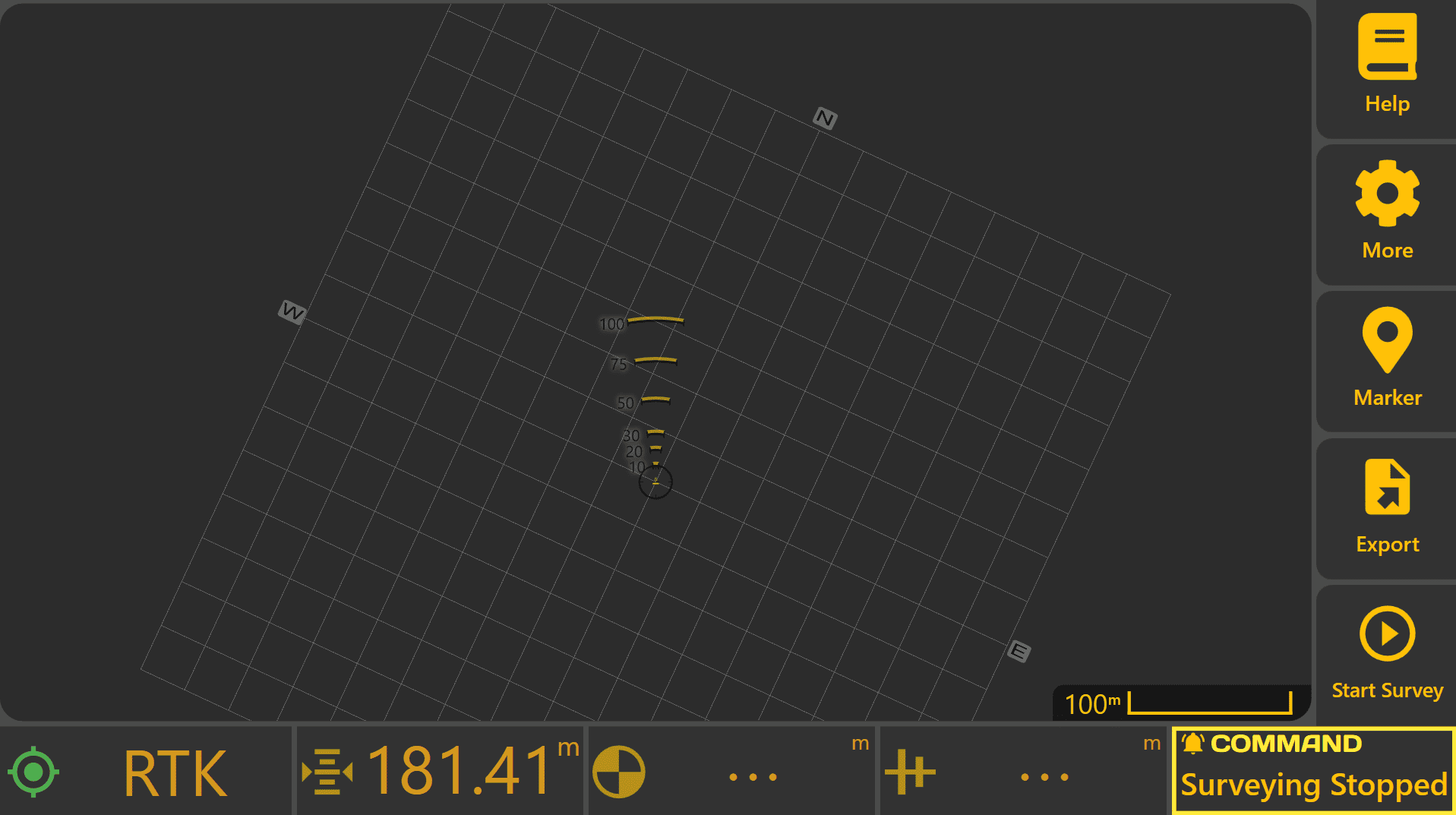
Starting a Survey
To begin a new survey:
- Press More → Start Survey.
- Select the location where the survey project will be saved.
- Press Save.
A new blank survey project will be created and displayed in the Work Area.
Before recording, verify that the GNSS receivers have achieved an RTK fix. Survey accuracy is directly dependent on GNSS positioning quality.
Survey Types
Before recording begins, choose the type of survey to perform.
Boundary
Records the perimeter of a field or work area to define the project boundary. Boundary surveys are commonly used to define the project extents before creating a design.
Drains / Paths

Records linear features such as drains, channels, roads or access tracks.
Full Field
Records terrain data across the entire work area to produce a complete surface model.

Recording Survey Data
Once the survey type has been selected:
- Press Start Survey.
- Drive the machine through the area to be surveyed while maintaining RTK positioning.
- Follow the appropriate path for the selected survey type.
- Press Pause if recording needs to be temporarily suspended.
- Press Start Survey again to continue recording.
- Press Stop once the survey is complete.
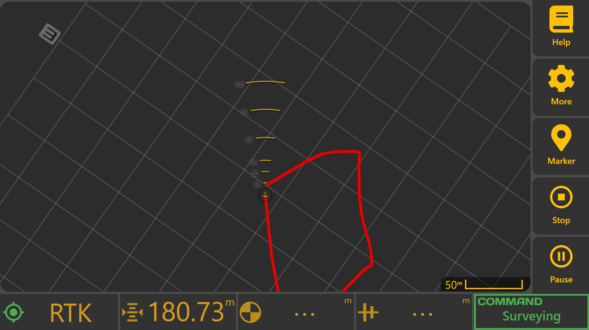
If a mistake is made before completing the survey, press Cancel to discard the current survey and begin again.
Additional Boundary, Drain/Path or Full Field surveys can be recorded by pressing Start Survey again after completing the previous survey.
 Recording Markers
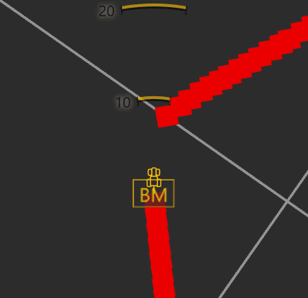 Before exporting the survey, it is often useful to create any important project markers, such as:
- Benchmark locations.
- Obstacles or hazards.
- Fence lines or gateways.
- Trees, poles or irrigation equipment.
- Other significant field features.
These markers become part of the exported project and provide useful reference points during design creation, construction and future verification.
Exporting Survey Data
Once all required survey data has been collected:
- Press Export.
- Select the desired export format.
- Choose the destination folder.
- Press Export.
Currently supported export formats include:
| Format | Purpose |
|---|---|
| .tci | Native T3RRA project format. |
| FieldLevel XML | Export for compatible third-party design software. |
The exported survey file can then be supplied to a designer or imported into another compatible application for further processing.
Operator Tip: Survey quality directly affects design quality. Maintain a consistent machine speed, achieve RTK positioning before recording, and collect sufficient coverage of the entire area with adequate overlap between passes. Missing sections or poor-quality survey data can lead to inaccurate designs and additional work later.
5.7 | Markers & Benchmarks
Level COMMAND allows important locations within a project to be recorded using Markers and Benchmarks. Although both are created using the same tool, they serve different purposes during surveying, grading and future site visits.
Markers provide useful reference points for operators and designers, while Benchmarks provide permanent reference locations used for project alignment and zeroing.
Marker Types
Two marker types are available:
General Markers
General Markers record locations or features of interest within a project. They are commonly used to identify:
- Trees or obstacles
- Fence lines and gateways
- Irrigation equipment
- Utility crossings
- Rocks or hazards
- Other significant site features
General Markers provide useful visual reference points but cannot be used when performing a benchmark zero.
Benchmark Markers
Benchmark Markers are permanent reference locations used for project alignment and zeroing.
Unlike General Markers, Benchmark Markers can be selected from the Zero to Benchmark tool and allow a project to be accurately re-aligned during future grading operations.
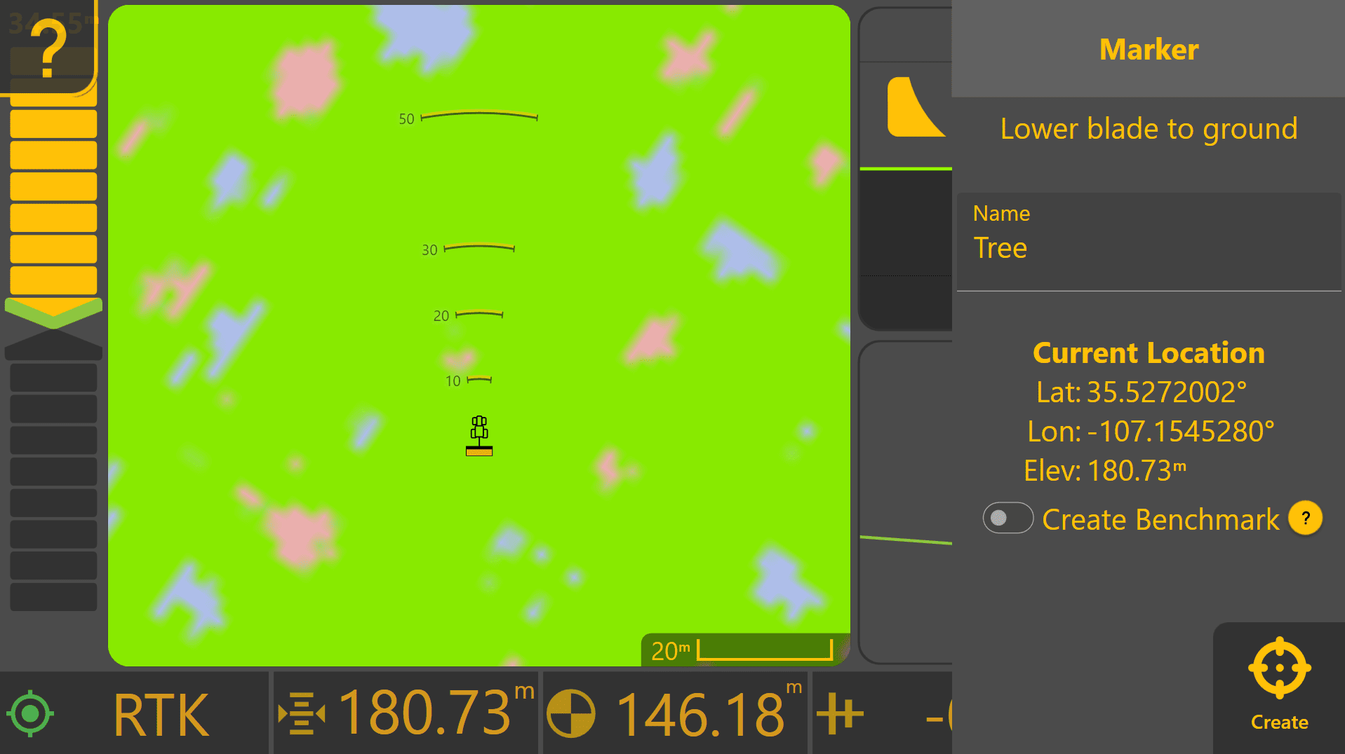
Creating a Marker
To create a General Marker or Benchmark Marker:
- Press Marker from the Apply View.
- Enter a descriptive marker name.
- Enable Create Benchmark if the marker will be used for zeroing.
- Press Create.
The current latitude, longitude and elevation are recorded as part of the marker.
Choosing a Good Benchmark
A Benchmark should be created at a location that can be accurately relocated throughout the life of the project.
Whenever possible, choose a location that:
- Will remain undisturbed during construction.
- Has a flat, stable surface.
- Allows the implement to be positioned accurately.
- Provides sufficient room to safely manoeuvre the machine.
- Can be easily recognised during future visits.
Examples include:
- Concrete pads
- Road shoulders near field entrances
- Survey monuments
- Permanent fence corners
- Other clearly identifiable locations
Avoid locations that are likely to be excavated, filled, cultivated or otherwise disturbed during the project.
When recording a Benchmark from the Apply View, lower the implement onto the ground before creating the marker so the recorded elevation represents the working surface.
Markers During Surveying
Markers can be created at any time, but they are particularly useful while surveying.
Recording important locations before exporting survey data allows those features to become part of the exported project, providing valuable reference information for designers, contractors and future machine operators.
Common markers recorded during a survey include:
- Benchmark locations
- Gateways and access points
- Fence corners
- Irrigation infrastructure
- Power poles and utility crossings
- Trees or significant obstacles
- Drain inlets, outlets and other important field features
Including these reference points within the survey often reduces the need for additional site visits and improves communication between the operator and designer.
When to Create Benchmarks
Creating a new Benchmark is appropriate when:
- Surveying an area for future design work.
- An imported project does not already contain a suitable Benchmark.
- Establishing a permanent reference point for future verification.
When creating a Plane Project, the Plane Origin is automatically stored as a Benchmark Marker and can be used later for re-zeroing the Plane if required.
If an imported project already contains surveyed Benchmarks, these should normally be used instead of creating new ones.
Important Considerations
Creating a Benchmark does not improve GNSS accuracy.
Instead, Benchmarks improve repeatability by allowing the machine to return to the same physical reference point whenever the project is revisited. This helps maintain alignment between the project and the real world over time.
Poorly chosen Benchmark locations may introduce alignment errors if the ground surface changes, the location is disturbed, or the implement cannot be positioned consistently.
Operator Tip: Treat Benchmark Markers as permanent project reference points. Spending a few extra minutes selecting a stable, easy-to-find location can save considerable time when returning to the project months or even years later.
Once you are familiar with creating Markers and Benchmarks, continue to 5.8 | Choosing a Zeroing Method, which explains how different zeroing workflows are selected for Plane Projects, imported designs and existing surfaces.
5.8 | Choosing a Zeroing Method
Selecting the correct zeroing method depends on how the current project was created and whether a suitable Benchmark is available.
The table below summarises the recommended workflow for the most common situations.
| If your project is... | Recommended zeroing method |
|---|---|
| A newly created Plane Project | No additional zeroing is normally required. Defining the Plane Origin using Use GPS establishes the Plane reference. |
| An existing Plane Project being reopened | Zero to the Plane Origin Benchmark if the alignment requires verification or the GNSS reference has changed. |
| An imported design containing Benchmarks | Zero to the supplied Benchmark Marker. This is the preferred method whenever surveyed Benchmarks are available. |
| An imported design without Benchmarks | Create a Benchmark Marker, then perform a Benchmark Zero using the newly created Benchmark. |
| An existing finished surface requiring a small alignment adjustment | Use Set Z to Current to shift the design vertically to the existing surface. This is an advanced workflow and should only be used when appropriate. |
Frequently Asked Questions
Do I need to zero a new Plane Project?
Usually not. When the Plane Origin is created using Use GPS, the Plane is aligned to the current implement position and elevation. The Origin is automatically stored as a Benchmark Marker and can be used later if the Plane needs to be re-zeroed.
Should I create another Benchmark for a Plane Project?
Not normally. The Plane Origin already serves as the primary Benchmark for the Plane.
Additional Benchmarks may be useful on very large sites where returning to the Origin is inconvenient, but they are not generally required.
Should I always use a surveyed Benchmark if one is available?
Yes. Surveyed Benchmarks provide the most repeatable project alignment and should always be preferred over creating a new Benchmark.
When should I create a new Benchmark?
Create a new Benchmark when importing a project that does not already contain one, or when establishing a permanent reference point for future verification and re-zeroing.
When should I use Set Z to Current?
Use Set Z to Current only when aligning a design to an existing finished surface or making a small vertical alignment adjustment.
It should not replace normal Benchmark Zeroing where a suitable Benchmark is available.
How often should I re-zero?
Re-zeroing is normally only required when:
- Returning to a project after a significant period of time.
- Changing or relocating the GNSS base station.
- Alignment is suspected to have changed.
- Project verification indicates the design no longer matches the ground.
Repeatedly zeroing during normal grading is generally unnecessary and may introduce unwanted alignment changes if performed on an unsuitable location.
Operator Tip: Choose one reliable Benchmark and continue using it throughout the project whenever possible. Consistently using the same reference point makes verification easier and helps maintain repeatable project alignment over time.
What's next?
The workflows in this chapter explain how to create projects, collect survey data, place markers and prepare a machine for grading.
The next chapter explains how Level COMMAND interprets this information to control the implement automatically, including surface layers, target generation, predictive control and blade behaviour.