4 | Operator Quick Start
The purpose of this chapter is to guide operators through the basic workflow of using Level COMMAND, from system startup through to performing the first pass safely and confidently.
- 4.1 | System Startup
- 4.2 | Understanding COMMAND Status
- 4.3 | Loading or Creating a Project
- 4.4 | Setting Zero
- 4.5 | Engaging Automatic Control
- 4.6 | Performing Your First Pass
- 4.7 | Closing Level COMMAND
4.1 | System Startup
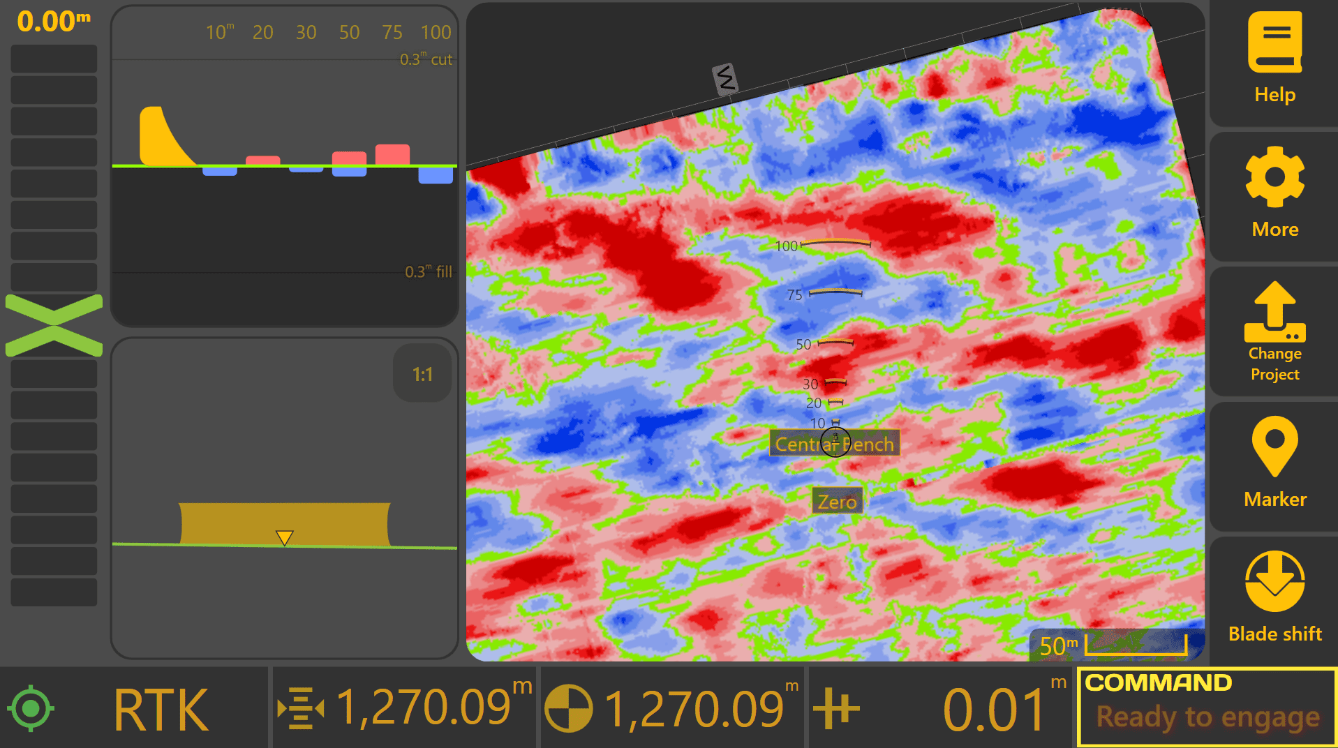
When Level COMMAND is first started, the Apply View will be displayed. Before loading a project or attempting to engage Automatic Control, perform the following readiness checks.
Verify GNSS Operation
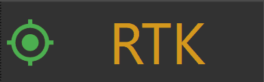
Once the machine is powered on, allow the GNSS receiver(s) several minutes to initialise and obtain RTK corrections.
GNSS status can be checked using either:
- The GNSS status widget on the Apply View.
- More → COMMAND Settings → Inputs / Offsets.
If using the Inputs / Offsets page, verify that each configured GNSS receiver displays a Fix Type of RTK before proceeding.
Automatic Control requires RTK-quality positioning for accurate operation. Lower quality fix types such as GPS, Differential GPS or Float RTK may reduce positioning accuracy and automatic control performance. To prevent inaccurate machine control, the COMMAND ECU will not allow Automatic Control to engage unless all required GNSS receivers have achieved an RTK fix.
If RTK fix type has not been achieved after several minutes, common causes include:
- GNSS receiver still initialising.
- RTK radio or correction service unavailable.
- Poor antenna visibility due to nearby trees, buildings or obstructions.
- Incorrect GNSS receiver configuration.
- Damaged or disconnected GNSS hardware.
Refer to Section 3 | Dealer Installation & Commissioning if GNSS configuration requires adjustment.

Check COMMAND Status
Once GNSS operation has been verified, review the COMMAND Status indicator shown at the bottom-right of the Apply View.
The COMMAND Status provides information about the current operating state of the system, including whether:
- Additional setup is required.
- Automatic Control is ready to engage.
- A warning or fault condition is present.
If the system has not previously been configured or commissioned, consult your dealer or refer to Section 3 | Dealer Installation & Commissioning.
Continue to 4.2 | Understanding COMMAND Status for detailed information about the status indicator and its various operating states.
4.2 | Understanding COMMAND Status
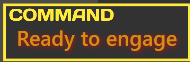
The COMMAND Status area is shown at the bottom-right of the Apply View and provides a quick indication of the current operating state of the COMMAND ECU.
Operators should check COMMAND Status before attempting to engage Automatic Control. The status message indicates whether the system is ready to engage, currently engaged, waiting for an operator action, or unable to operate due to a warning, fault or incomplete setup condition.
Status Colours
The coloured frame around the COMMAND Status area provides a quick visual indication of the current system state:
- Green indicates that Automatic Control is currently engaged.
- Yellow indicates that all requirements have been satisfied and the system is ready for Automatic Control engagement.
- Red indicates that operator action, further setup or fault correction is required before Automatic Control can operate normally.


Typical Workflow
Before engaging Automatic Control:
- Confirm GNSS has achieved RTK fix.
- Confirm the correct project or design surface is loaded.
- Check COMMAND Status.
- Resolve any warnings or required actions.
- Engage Automatic Control only when COMMAND Status shows Ready to Engage.
Green Statuses - Automatic Control Engaged
Green statuses indicate that Automatic Control is currently engaged.
| Status | Meaning | Operator Action |
|---|---|---|
| Engaged - Active | Automatic Control is engaged and COMMAND may move the implement automatically. | Continue operating normally. |
| Engaged - Low Speed | Automatic Control is engaged, but the machine is moving too slowly for COMMAND to move the implement. | Increase machine speed above 0.2 km/h to allow automatic implement movement. |
| Engaged - Calibrating | COMMAND is controlling the implement as part of a calibration process. | Continue the calibration procedure shown on screen. |
Yellow Statuses - Ready for Engagement
Yellow statuses indicate that the system is ready for Automatic Control, but Automatic Control is not currently engaged.
| Status | Meaning | Operator Action |
|---|---|---|
| Ready to Engage | The system is ready for Automatic Control. | Press the engage button when ready to begin. |
Red Statuses - Operator Attention Required
Red statuses indicate that operator action, additional setup or fault correction is required before Automatic Control can operate.
| Status | Meaning | Operator Action |
|---|---|---|
| Waiting for RTK | The GNSS receiver does not have RTK correction yet. | Wait for RTK. Check GNSS corrections and receiver setup if RTK is not achieved after several minutes. |
| No Connection to ECU | Level COMMAND cannot communicate with the COMMAND ECU. | Check ECU power, wiring and connections. |
| Blade Width Unset | The selected machine profile has not been fully configured. | Contact your dealer or complete machine setup before continuing. |
| Waiting for Manual SCV Input | The tractor requires the hydraulic control lever to be moved before Automatic Control can operate. | Briefly move the required hydraulic control lever. |
| System Not Armed | Automatic Control has not been armed. | Turn the arm/engage switch on, or cycle it off and back on if required. |
| SCV Locked | The tractor hydraulic valve is locked and cannot be controlled by COMMAND. | Unlock the required hydraulic valve using the tractor controls. |
| Speed Too Fast | Machine speed is above the maximum allowed Automatic Control speed. | Reduce machine speed before engaging Automatic Control. |
| Waiting for IMU Data | COMMAND is not receiving data from the IMU sensor. | Check IMU power, wiring and configuration. |
| Unstable GPS / IMU | GNSS or IMU data is changing too quickly or appears invalid. | Stop and allow the system to stabilise. Check sensor mounting and signal quality if the warning remains. |
| NMEA Low Rate | GNSS position updates are arriving slower than expected. | Check GNSS receiver settings and connections. |
| T3 Timeout | COMMAND has stopped receiving control information from Level COMMAND. | Check the tablet, software and ECU connection. |
| No Active Control Valves | No hydraulic valves have been assigned to the active control function. | Complete machine setup or contact your dealer. |
| Check Calibration | Hydraulic calibration has not been completed. | Complete the calibration process before continuing. |
| Valve Error | A hydraulic valve or valve output has reported an error. | Check valve wiring, configuration and hydraulic hardware. |
| No Main License | Level COMMAND is not licensed for operation. | Enter a valid software unlock code. |
| Var Reset Required | The ECU requires additional setup after a firmware update. | Contact your dealer or T3RRA Support. |
Ready To Continue
Once COMMAND Status shows Ready to Engage, the system is ready for Automatic Control engagement.
Continue to 4.3 | Loading or Importing a Project if a project has not yet been loaded, or continue to 4.5 | Engaging Automatic Control if the project and zero reference are already prepared.
4.3 | Loading or Creating a Project
Loading a Design File
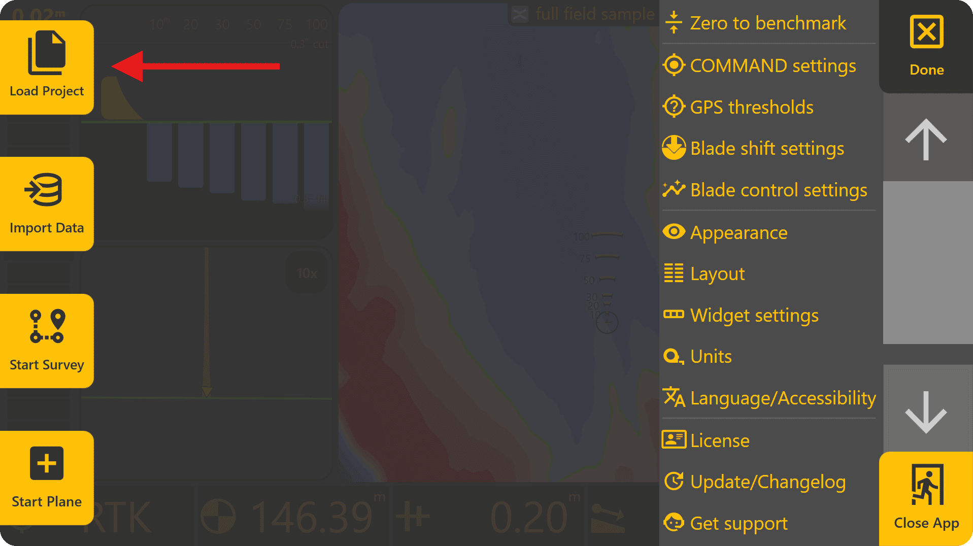
To load a design file, press Done at the top-right to return to the Level COMMAND apply page, then press More > Load Project. This will open the Change Project page and display all .tad file projects. This file type is specific to LC and the software will automatically scan the file system to find all .tad files present - alternatively to find them manually press "Browse" on the right side of the screen.
Supported design formats:
• T3RRA Project (.tci)
• GPS Design (.gps)
• Existing Level COMMAND Plane Projects
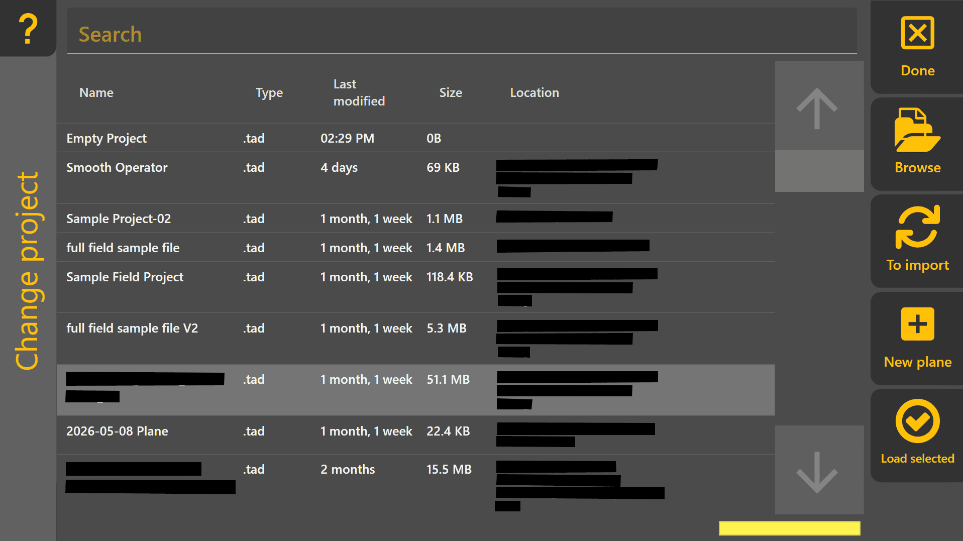
 Loading an Existing Level COMMAND Project
If loading an existing Level COMMAND project (.tad file type), select it from the list and press Load Selected.
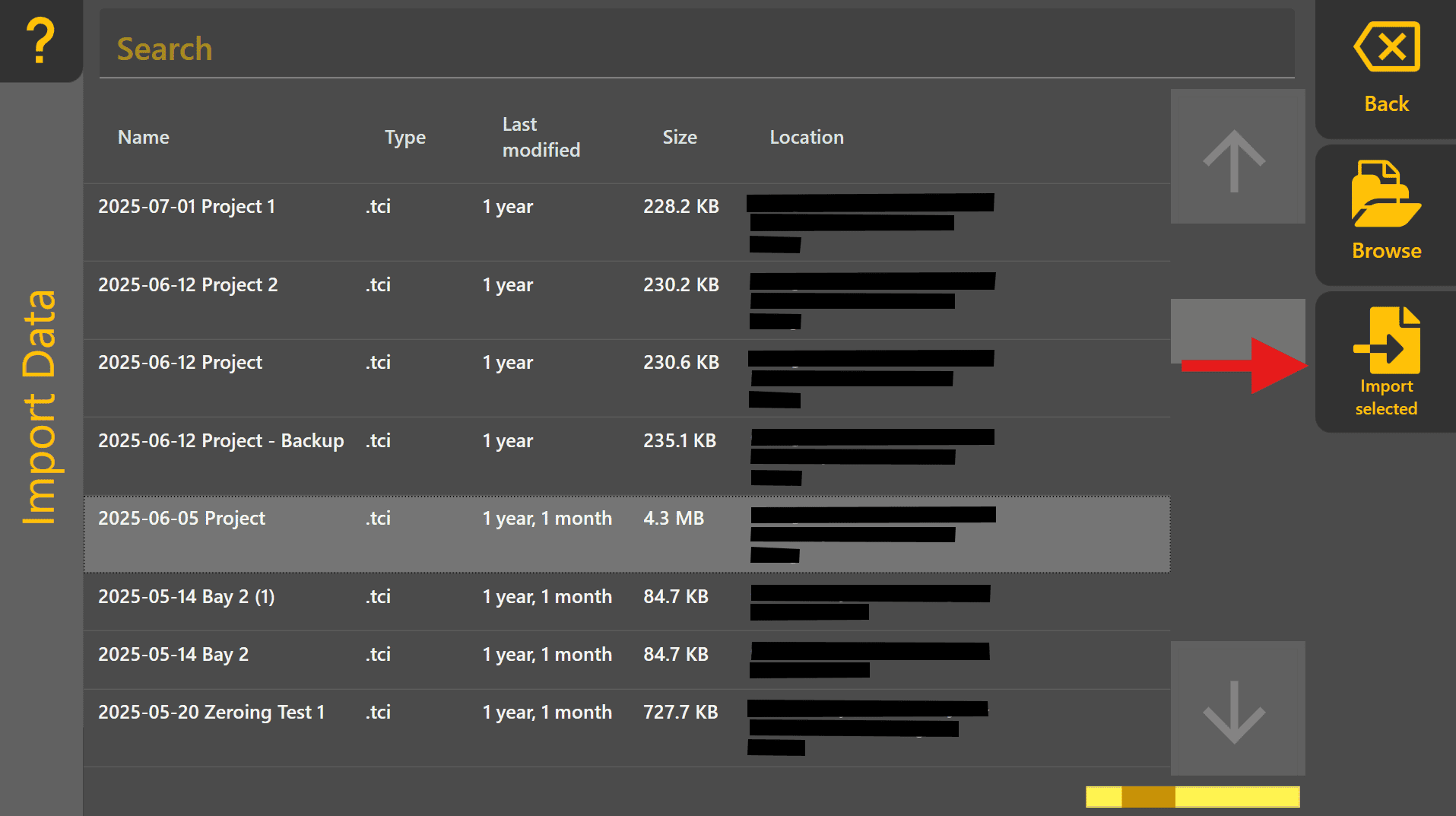
Loading an External Design File (Other File Types)
If loading a design of different file type, such as .tci, press "To Import" to move to the Import Data page. Select the design file from the list and then press "Import Selected".
Creating a Basic Plane Project
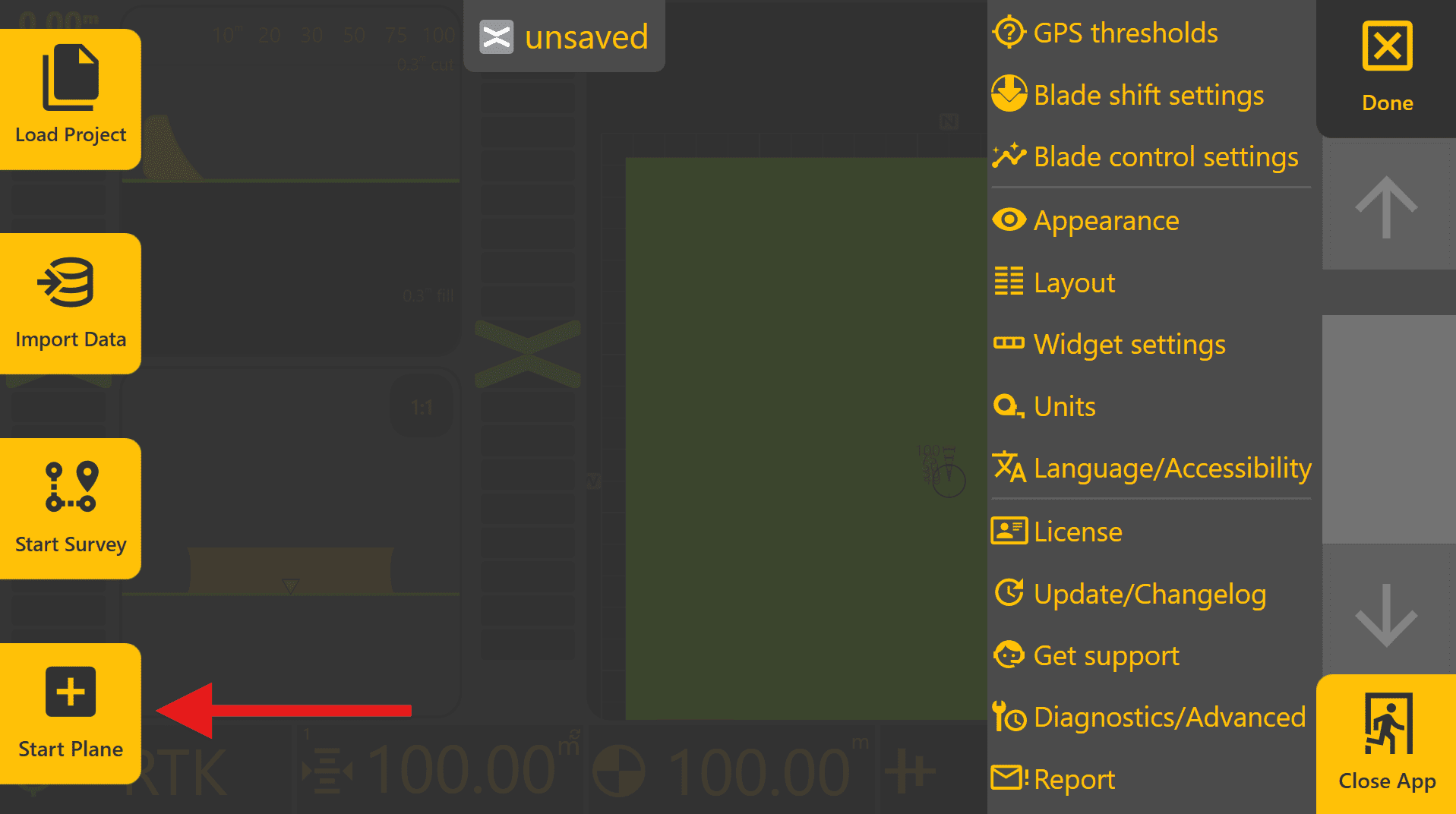
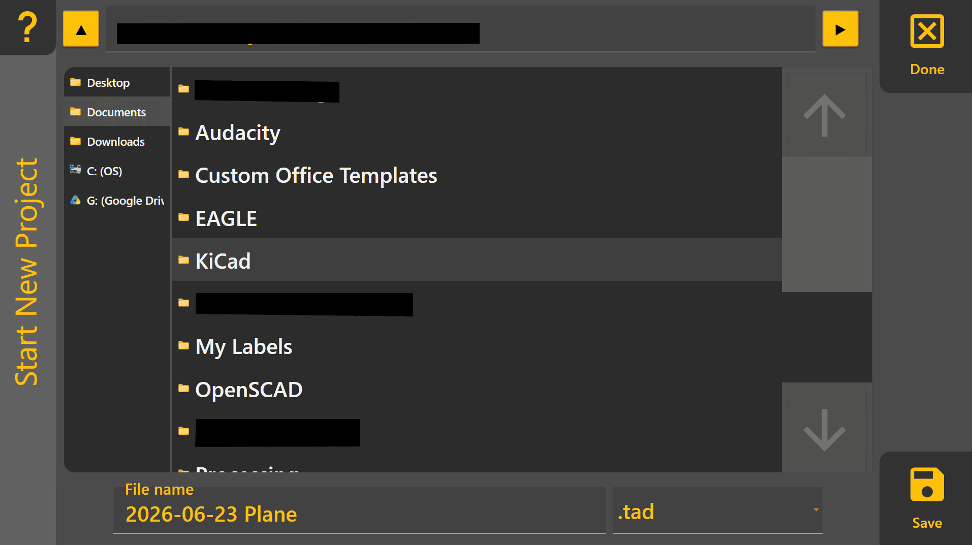
A Plane project is the quickest way to begin using Level COMMAND without importing an existing design. Plane projects are commonly used for machine testing, simple levelling work and creating flat pads. To create a basic 2D/3D plane project, begin by pressing More > Start Plane. Choose an appropriate location to save the plane project on the tablet PC and then name the project, then press "Save".
To begin designing a Plane:
- Press Planes, then select one of the available Plane slots.
- Press Create.
- Press Origin and then Use GPS to set the Plane origin to the current implement position.
- Press Okay to create a flat Plane surface.
The Plane can now be loaded and used for testing or levelling work.
If a sloped surface is required, press Slope and use Use GPS at a second location to automatically calculate the desired slope.
For detailed information on Plane projects, refer to Section 5 | Operational Workflows
4.4 | Setting Zero
What is Zeroing?
Zeroing aligns the machine to the design surface so that Level COMMAND can guide the implement to the correct elevation.
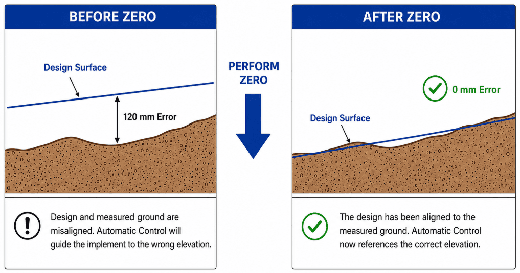
A valid zero is required before Automatic Control can operate accurately. If the machine is not correctly zeroed, Level COMMAND may display incorrect cut and fill values and guide the implement to the wrong elevation.
A valid zero should be established whenever:
-
Beginning a new project.
-
Returning to a project after an extended period of time.
-
Changing or relocating the GNSS base station.
-
Performing major project alignment or terrain alignment changes.
Different project types may require different zeroing methods. The most common workflows are described below.
Benchmark Markers
 Level COMMAND separates markers into two categories:
-
Benchmark Markers – Used for project alignment and zeroing.
-
General Markers – Used for recording locations and points of interest within a project.
Only Benchmark Markers can be selected when performing a benchmark zero. This helps prevent accidental alignment to an incorrect marker.
Benchmark Markers may be:
-
Imported as part of a design file.
-
Created manually using the Create Benchmark option when creating a Marker.
-
Generated automatically when creating Plane Origins.
Because Plane Origins are stored as Benchmark Markers, they can be used later when re-zeroing a Plane Project.
Zeroing a Plane Project

Plane Projects are normally zeroed during creation of the Plane itself.
When the Plane Origin is created using Use GPS, the Plane surface is aligned to the current implement position and elevation. If the Primary and Secondary Slopes are also defined using GPS positions, the Plane surface will automatically be aligned to those locations as well.
In most situations no further zeroing is required. However, if the project is reopened later or a different base station is being used, the Plane may need to be re-aligned.
To re-zero a Plane Project:
-
Position the implement at the Plane Origin.
-
Place the implement on the ground surface.
-
Press More → Zero to Benchmark.
-
Select the Plane Origin marker.
-
Press Zero.
The Plane Origin will be adjusted to match the current implement position and elevation.
By default, only elevation is adjusted. Latitude and Longitude can also be adjusted if required by disabling the Elevation Only option.
Zeroing a Design with a Benchmark
Many imported designs contain one or more surveyed benchmark locations. A benchmark is a known reference point that can be used to accurately align the machine with the design.
To zero using a benchmark:
-
Move the machine to the benchmark location.
-
Place the implement on the benchmark surface.
-
Press More → Zero to Benchmark.
-
Select the desired Benchmark Marker.
-
Press Zero.
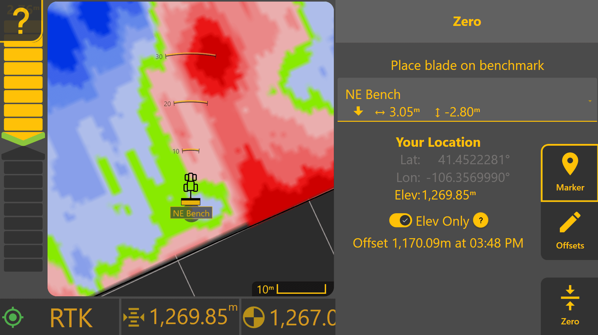
Level COMMAND will record and average approximately 30 seconds of GNSS data before applying the alignment. Once complete, verify that cut and fill values appear reasonable before beginning work.
Zeroing a Design without a Benchmark
If a design does not contain a benchmark, one should be created before beginning work.
Choose a location that:
-
Is easy to locate again later.
-
Will remain undisturbed throughout the project.
-
Represents a stable reference point.
- Is a wide area where the implement can be manoeuvred easily and positioned accurately on the marker.
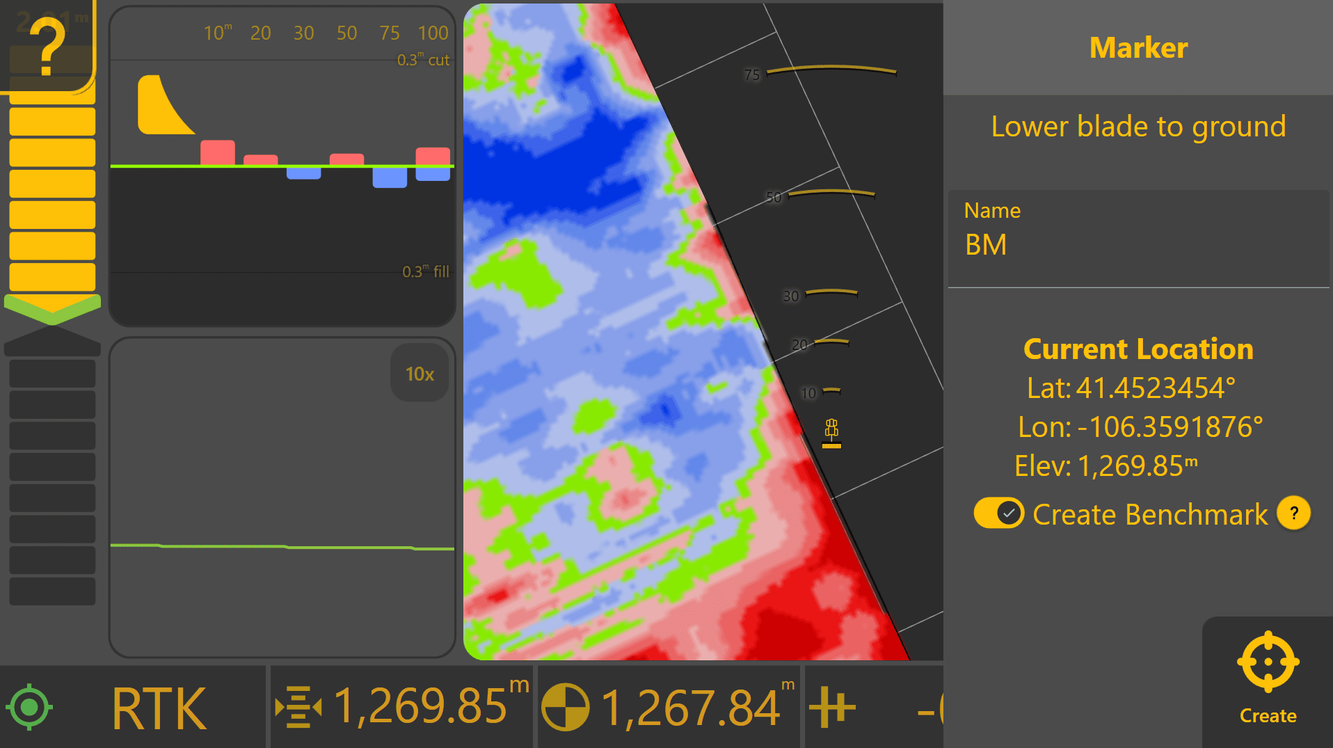
To create a Benchmark Marker:
-
Press Marker from the Apply View.
-
Enter a name such as Benchmark, Bench, BM or MB.
-
Enable Create Benchmark.
-
Press Create.
Once the Benchmark Marker has been created, perform the standard benchmark zeroing procedure described above for zeroing a design with a benchmark.
Zeroing to an Existing Surface (Advanced)
In some situations it may be desirable to align a design to an existing surface rather than a surveyed benchmark.
This method is commonly used when:
Choose an area that:
-
Has not been disturbed.
-
Is known to be on grade.
-
Can be located again later if required.
- Is a wide area where the implement can be manoeuvred easily and positioned accurately on the marker.
To align the design:
-
Position the implement on the chosen location.
-
Press More → Zero to Benchmark.
-
Press Offsets.
-
Press Set Z to Current.
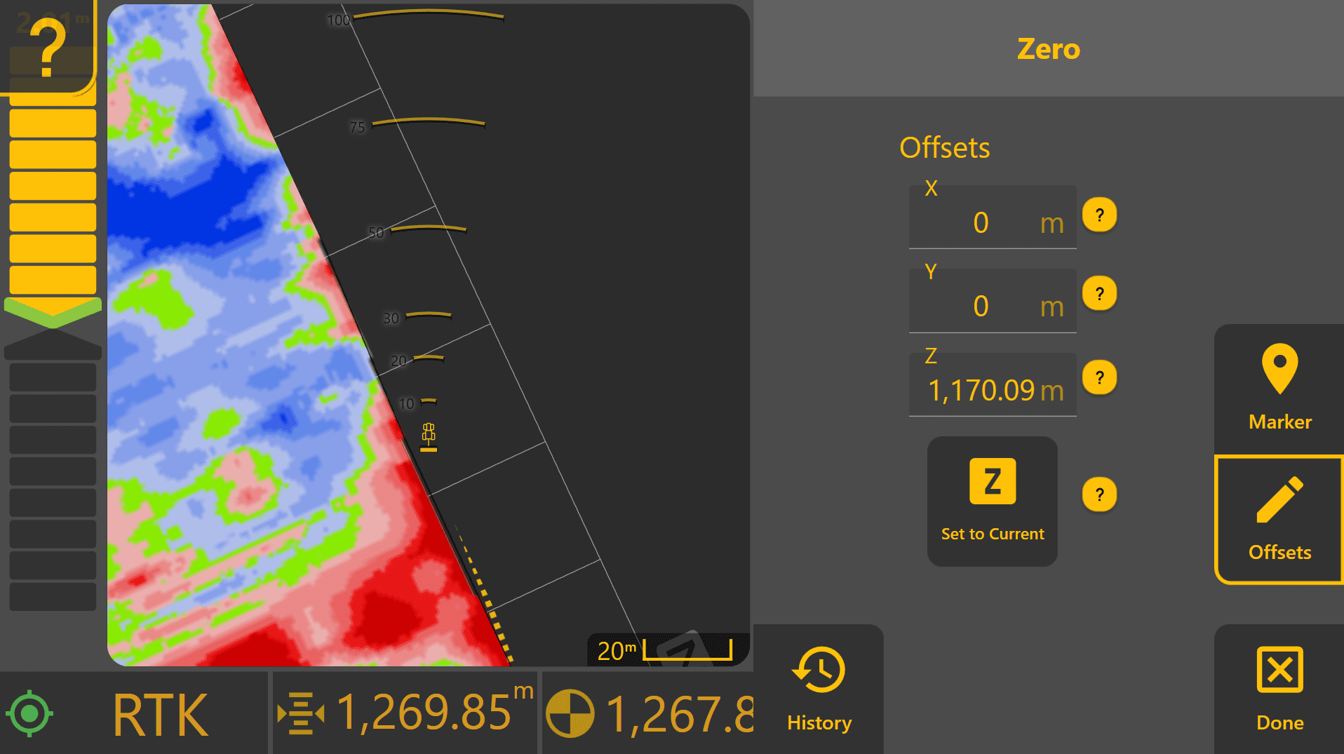
The design will be shifted vertically so that the current location becomes the new zero reference. Creating a marker at this location is highly recommended so it can be revisited later for verification, or re-zeroed using the Zeroing a Design with a Benchmark process described above.
Ready to Continue
Before engaging Automatic Control, verify that:
✓ A project is loaded.
✓ GNSS receivers have achieved RTK fix.
✓ COMMAND Status shows Ready to Engage.
✓ A valid zero has been established.
Continue to 4.5 | Engaging Automatic Control.
4.5 | Engaging Automatic Control
Before Engaging Automatic Control
Before engaging Automatic Control, verify that:
✓ A project is loaded.
✓ GNSS receivers have achieved RTK fix.
✓ A valid zero has been established.
✓ COMMAND Status displays Ready to Engage.
Ready to Engage indicates that all Level COMMAND and COMMAND ECU requirements have been satisfied and Automatic Control is available for engagement.
If COMMAND Status displays any other message, refer to 4.2 | Understanding COMMAND Status or the Troubleshooting chapter before continuing.
Arming the System

COMMAND installations use a three-position Arm/Engage switch:
Off → Armed → Engage (momentary)
The switch must be placed in the Armed position before Automatic Control can be engaged.
If COMMAND Status displays System Not Armed, verify that:
-
The Arm/Engage switch is in the Armed position.
-
The machine has not been restarted since arming the system.
-
The switch has not been accidentally moved to Off.
If necessary, cycle the switch to Off and then back to Armed.
Engaging Automatic Control

Once COMMAND Status displays Ready to Engage, momentarily press the Engage position of the Arm/Engage switch.
COMMAND Status will change to one of the following states:
Engaged - Active
Automatic Control is engaged and COMMAND may actively move the implement to follow the design surface.
Engaged - Low Speed
Automatic Control is engaged, but implement movement is currently disabled because machine speed is below 0.2 km/h.
Once machine speed increases above 0.2 km/h, COMMAND will automatically begin controlling the implement if cut/fill error is present.
Hydraulic Valve Activation
The Engage switch enables Automatic Control within the COMMAND ECU. Depending on the hydraulic system being used, additional tractor or machine controls may also need to be placed into automatic mode.
Common examples include:
-
Placing a tractor SCV / Auxiliary valve into detent mode.
-
Pushing an electronic SCV / Auxiliary valve lever past its normal travel to activate automatic operation.
-
Enabling machine-specific hydraulic automation functions.
If Automatic Control appears to engage correctly but no hydraulic movement occurs, verify that the hydraulic valve system has also been placed into automatic mode.
Disengaging Automatic Control
To disengage Automatic Control, momentarily press the Engage switch again.
COMMAND Status will return to Ready to Engage.
Automatic Control can then be re-engaged at any time by pressing the Engage switch again.
Automatic Disengagement
Automatic Control may automatically disengage if critical operating conditions are no longer satisfied.
Common causes include:
-
Loss of RTK positioning.
-
GNSS or sensor communication issues.
-
Hydraulic valve faults.
-
Loss of communication between Level COMMAND and the COMMAND ECU.
-
Machine-specific safety conditions.
If Automatic Control disengages unexpectedly, check COMMAND Status for additional information.
The last disengagement reason can also be viewed from the Apply View by pressing More → COMMAND Settings → Diagnostics.
Calibration Mode
When performing valve calibration, COMMAND Status may display Engaged - Calibrating.
In this mode, hydraulic movement will only occur while the operator is actively holding the Engage switch during a calibration test.
Releasing the Engage switch immediately stops movement. This behaviour provides an additional level of safety while calibrating hydraulic functions.
What to Expect During First Engagement
When Automatic Control is engaged for the first time:
-
The implement may not move immediately if it is already close to the design surface.
-
Small corrections may occur as COMMAND begins reducing cut/fill error.
-
Implement movement should become smoother as machine speed increases and consistent GNSS data is maintained.
-
Larger cut/fill errors will generally result in larger hydraulic commands.
Observe machine behaviour during the first pass and verify that implement movement matches the expected design direction.
If the implement consistently moves in the wrong direction, disengage Automatic Control immediately. The hydraulic valve extend/retract direction may need to be corrected using Swap Extend/Retract from More → COMMAND Settings → Valve Cals. Refer to the commissioning or troubleshooting sections if unsure.
Ready to Continue
Once Automatic Control can be engaged successfully and the implement responds correctly, continue to 4.6 | Performing Your First Pass.
4.6 | Performing Your First Pass
Understanding the Operator's Role
Level COMMAND automatically controls the implement to follow the selected design surface, but it does not decide where material should be moved from or where it should be placed.
The operator remains responsible for planning the earthmoving operation, including:
-
Selecting suitable cut and fill areas.
-
Determining haul directions and travel paths.
-
Deciding where material should be sourced from.
-
Deciding where material should be placed.
Careful planning can significantly improve productivity by reducing unnecessary material movement and minimising rework. Material that is moved multiple times before reaching its final location increases both operating time and fuel consumption.
Monitoring Automatic Control
Once Automatic Control is engaged, monitor the Apply View to verify that COMMAND is operating as expected.
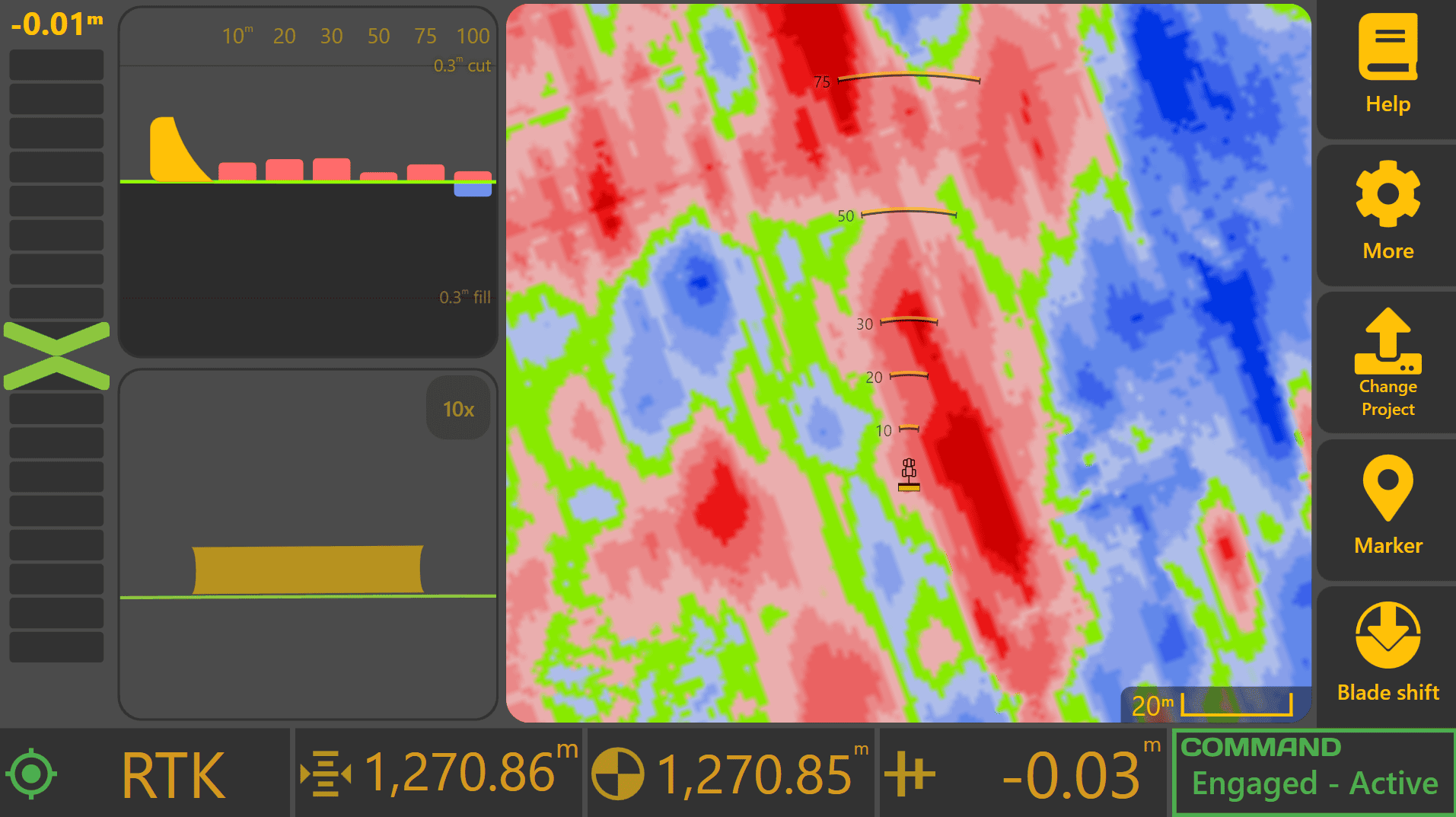
Important indicators include:
Error Chevron
The Error Chevron indicates whether the implement is above or below the design surface. As Automatic Control operates, the Error Chevron should generally move toward zero as the design elevation is approached.
Cross Section View
If using both Height and X-Slope control, monitor the Cross Section View to verify that both elevation and cross-fall are tracking correctly.
Cut/Fill Information
Monitor upcoming cut and fill values to understand how much material is approaching. Large cut or fill values may require a different operating strategy than smaller corrections.
Understanding the Control Profile
 The Control Profile provides a visual representation of the current Automatic Control target and implement position.
To display the Control Profile, press Blade Shift from the Apply View. The Control Profile will appear on the right side of the screen.
The profile displays:
Original
The original surveyed surface elevation.
Target
The elevation that Automatic Control is currently attempting to achieve.
Design
The final design elevation.
Current
The current measured implement elevation.
As Automatic Control operates, the Current position should generally move toward the Target position.
If Dynamic Cut Limit or Dynamic Fill Limit is active, the Target position may intentionally differ from the Design elevation. The shaded area of the Control Profile indicates material that will not be cut or filled during the current pass.
Using Blade Shift
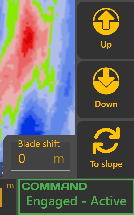
Blade Shift allows the operator to temporarily raise or lower the Automatic Control target without modifying the underlying design surface.
Use the Up and Down buttons to adjust the shift value.
Common uses include:
-
Leaving additional material for later trimming.
-
Reducing cutting depth during difficult conditions.
-
Making temporary grading adjustments without changing the design.
Blade Shift affects Automatic Control behaviour only and does not modify the design file.
Using Cut/Fill Limit
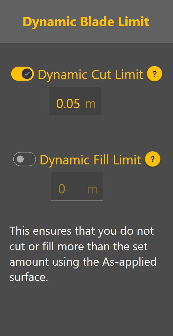
Cut/Fill Limiting allows Automatic Control to progressively work toward the design surface over multiple passes.
To access Cut/Fill Limiting:
-
Press Blade Shift.
-
Press Blade Limit.
-
Enable Dynamic Cut Limit and/or Dynamic Fill Limit.
-
Enter the desired limit value.
For example:
A Dynamic Cut Limit of 0.05 m will cause Automatic Control to target only 5 cm of cut during each pass, even if the full design requires a larger cut.
This can assist with:
-
Reducing blade loading.
-
Preventing machine overload.
-
Improving material control.
-
Maintaining smoother machine operation.
Multiple passes may be required to reach final grade when Cut/Fill Limiting is enabled.
Changing Surface Display Modes
Different map layers can be displayed depending on the information required.
Display settings can be changed from:
More → Appearance
Common display modes include:

Design
Displays the intended finished design surface.
 As Elevation

Displays the measured surface elevation collected during operation.
 As Cut/Fill

Displays current cut and fill values based on the latest surveyed surface.
The As Elevation and As Cut/Fill layers update dynamically as work progresses, making them useful for monitoring grading performance during operation.
Signs That Automatic Control Is Working Correctly
During normal operation:
-
The Error Chevron generally trends toward zero.
-
The Current value in the control profile moves toward the Target value.
-
The worked area updates on the map.
-
The finished surface visually matches the displayed cut/fill changes.
-
COMMAND Status remains Engaged - Active.
If Performance Appears Incorrect
If the implement appears slow to respond, struggles to reach grade or behaves erratically, verify that commissioning and calibration have been completed correctly.
Common causes include:
-
Incorrect valve calibration.
-
Hydraulic systems not placed into automatic mode.
-
Poor GNSS quality.
-
Tracking Sensitivity requiring adjustment.
Tracking Sensitivity controls the overall aggressiveness of Automatic Control:
-
Values that are too low may result in slow response and difficulty reaching target grade.
-
Values that are too high may result in excessive corrections and unstable implement movement.
If required, adjust Tracking Sensitivity in small increments and observe the resulting behaviour.
Verifying the Completed Pass
Once a pass has been completed, inspect both the worked surface and the map display. The completed area should generally show reduced cut/fill values and move closer to on-grade conditions. Multiple passes may be required where large cut or fill values are present.
In some situations, manual intervention may still be required to relocate material efficiently between cut and fill areas.
Confirming Surface Accuracy
Inspect the completed surface and check for:
-
Washboarding.
-
Dips.
-
High spots.
-
Surface irregularities.
If concerns remain about the accuracy of the completed work, a survey may be performed and compared against the updated surface displayed within Level COMMAND.
Ready to Continue
Once Automatic Control is producing smooth implement movement and the completed surface matches expectations, continue operating normally.
Refer to Chapter 5 for additional operational workflows and Chapter 6 for detailed information on Automatic Control behaviour. Continue on to 4.7 | Closing Level COMMAND.
4.7 | Closing Level COMMAND
Before Closing Level COMMAND
Before closing Level COMMAND, verify that:
✓ Automatic Control has been disengaged.
✓ Hydraulic functions have been returned to manual operation.
✓ The machine is in a safe operating condition.
✓ The implement has been lowered safely to the ground where appropriate.
If COMMAND Status shows Engaged - Active or Engaged - Low Speed, disengage Automatic Control before continuing.
Saving Your Work
Projects, design files, Plane surfaces, markers and configuration changes are saved automatically as they are created or modified. In normal operation, no manual save process is required before exiting Level COMMAND.
Although work is saved automatically, it is good practice to close Level COMMAND before shutting down the tablet or PC.
If you wish to manually save a copy of the current project:
- Press More.
- Press the current project name at the top of the window.
- Press Save As.
- Select the desired save location.
- Press Save.
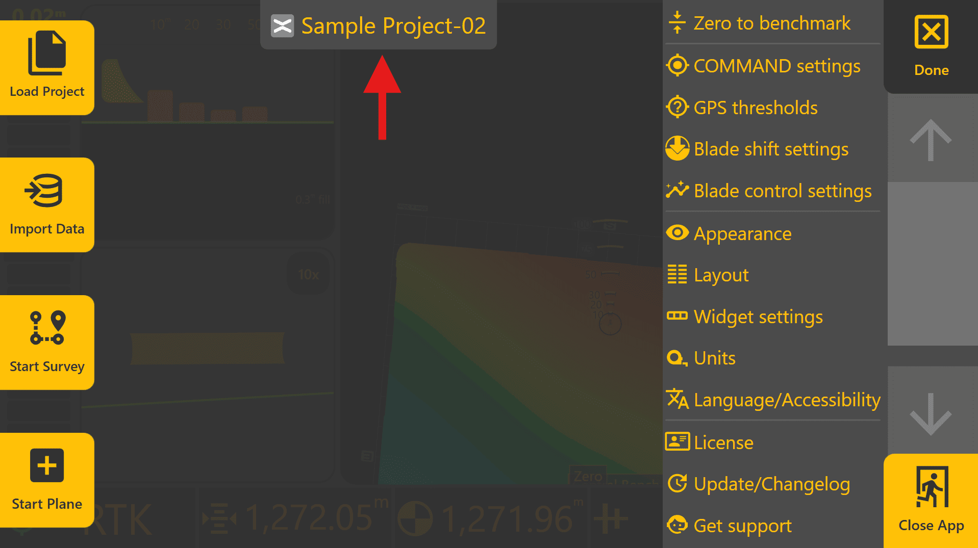
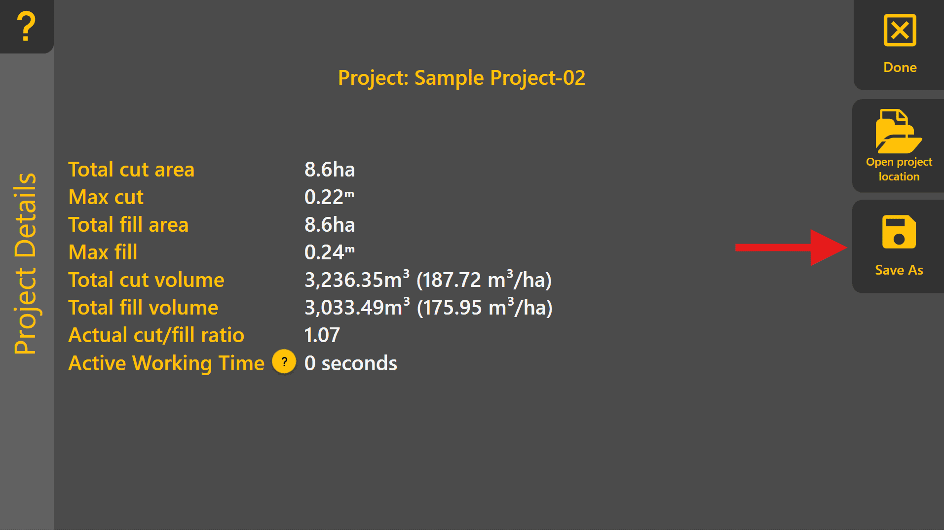
This can be useful when creating backups, archiving completed projects or creating a modified copy of an existing project.
Closing the Application
To close Level COMMAND:
-
Press More.
-
Press Close App at the bottom right.
-
Press Yes.
The application will close and return to the operating system.
Automatic Startup
Level COMMAND can be configured to start automatically when Windows starts.
To modify this setting:
More → Diagnostics/Advanced
Use the Start Level COMMAND when computer starts option to enable or disable automatic startup. This setting is enabled by default.

Unexpected Shutdowns
If the tablet or PC unexpectedly shuts down, COMMAND will automatically disengage Automatic Control once position updates are no longer received from Level COMMAND.
The operator immediately becomes responsible for machine control and implement position.
If an unexpected shutdown occurs:
-
Raise the implement if necessary.
-
Return hydraulic controls to a safe state.
-
Restart the tablet or PC.
-
Start Level COMMAND and verify system readiness before continuing work.
Because project information is saved automatically, work progress will normally be retained after restarting the application.
Restarting Level COMMAND
When Level COMMAND is started again:
-
The previous project remains available.
-
Previously created Plane surfaces and markers remain available.
-
Machine configuration and calibration settings remain stored within the COMMAND ECU.
Automatic Control will not automatically re-engage after restarting the application. The operator must verify system readiness and manually engage Automatic Control before continuing work.
Quick Start Complete
You have now completed the basic Level COMMAND Quick Start workflow:
-
Start Level COMMAND.
-
Check COMMAND Status.
-
Load or create a project.
-
Set Zero.
-
Engage Automatic Control.
-
Perform a pass.
-
Exit Level COMMAND safely.
For additional workflows, project creation tools and advanced operating procedures, continue to Chapter 5 | Operational Workflows.