Before proceeding with machine configuration and calibration, ensure both the **Level COMMAND** application and the **COMMAND** ECU are updated to the latest available versions.
### Recommended Procedure 1. Connect to the **COMMAND** ECU successfully as performed in section 3.1. 2. [](https://docs.t3rra.com/uploads/images/gallery/2026-06/TUzVYDr2tXzmEQPZ-image.png)Press **Back** to return to the COMMAND Settings Overview page, then press **Done** to return to the Apply View. 3. Check for available **Level COMMAND** software updates by pressing **More** > **Update/Changelog** > **Download Updates**: 4. Allow the updates to complete and restart **Level COMMAND** if prompted. 5. Return to the Apply View. 6. Check for available **COMMAND** ECU firmware updates by pressing **More** > **COMMAND** **Settings** > **Admin** > **Update to Latest**. 7. Allow any updates to install completely. 8. Restart the ECU by turning off the machine and restarting. [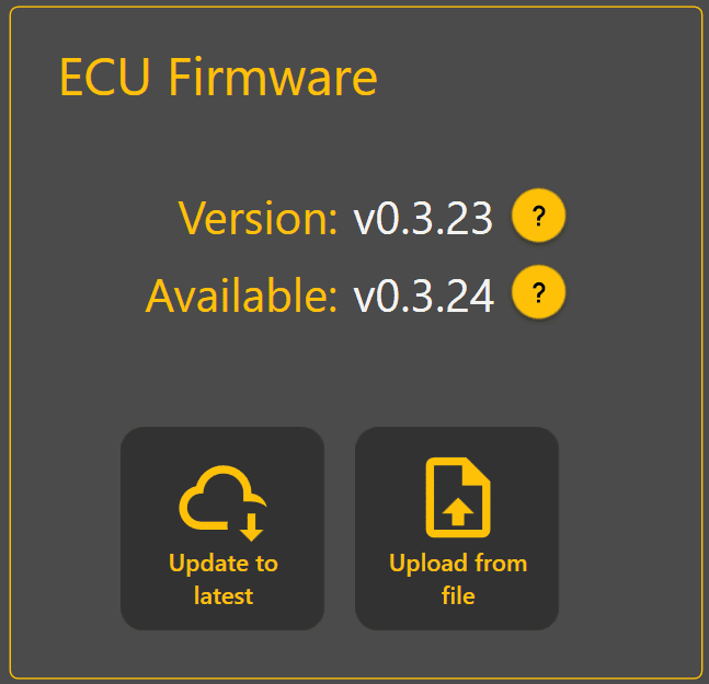](https://docs.t3rra.com/uploads/images/gallery/2026-06/y1MJHOlELbpPnBAi-image.png) Software and firmware updates may include: - Feature improvements - Bug fixes - GNSS compatibility updates - Calibration improvements - Stability enhancements After updating: - Verify communication with the ECU - Ensure no active faults or warnings are present at machine-level. Continue to **3.3 | Selecting A Machine Profile**. # 3.3 | Selecting A Machine Profile [](https://docs.t3rra.com/uploads/images/gallery/2026-06/MCK63PonelH71g36-image.png) #### Profile The profile is used to select the type of implement being used, for detailed information on available profiles please refer to the **COMMAND** hardware manual section. [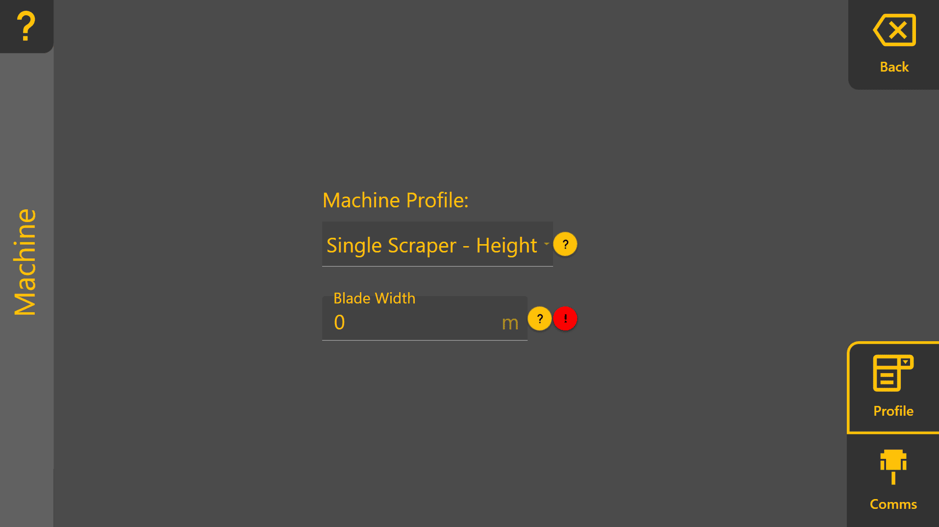](https://docs.t3rra.com/uploads/images/gallery/2026-06/pvdh4I0GKdIBhX6h-image.png) After selecting the appropriate machine profile, enter a **Blade Width** in the field shown - a red exclamation mark icon indicates that the blade width has not been set yet. [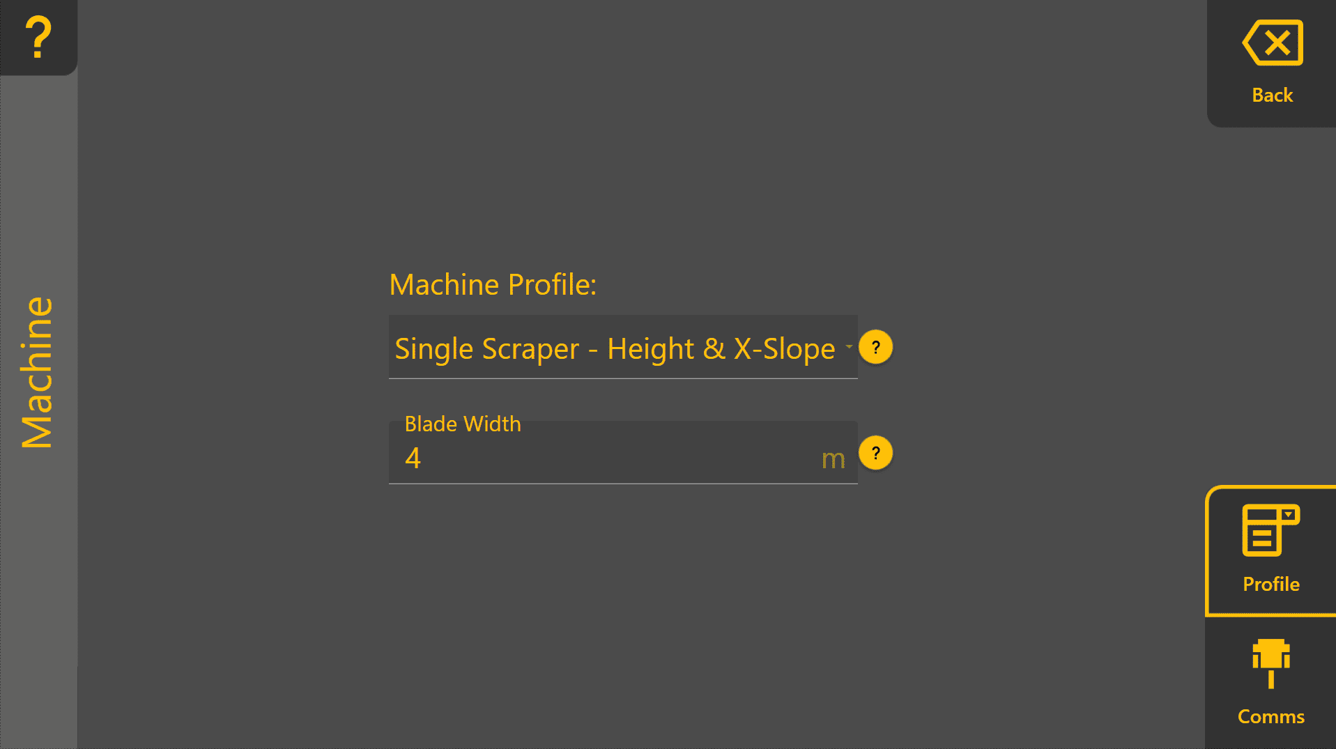](https://docs.t3rra.com/uploads/images/gallery/2026-06/YAJeEfaKtSCNCKno-image.png) Press "**Back**" to return to the COMMAND Settings Overview and continue to **3.4 | Configuring GNSS**. # 3.4 | Configuring GNSS [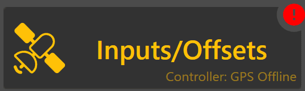](https://docs.t3rra.com/uploads/images/gallery/2026-06/DhYJngg9ARG4DGPq-image.png) The Inputs/Offsets page is used for selection of input sensors, such as GNSS receivers for height control or Inertial Measurement Units (IMU) for terrain compensation and Tilt / X-slope control. ## GNSS Input Configuration ### Inputs [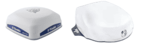](https://docs.t3rra.com/uploads/images/gallery/2025-08/hRW9UdPLSeukmTOw-image.png)[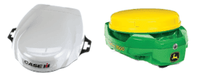](https://docs.t3rra.com/uploads/images/gallery/2025-08/Hkj7n3SvxxO2duCs-image.png) All **COMMAND** machine profiles have at least one height control function intended for use with a GNSS receiver for vertical position feedback. [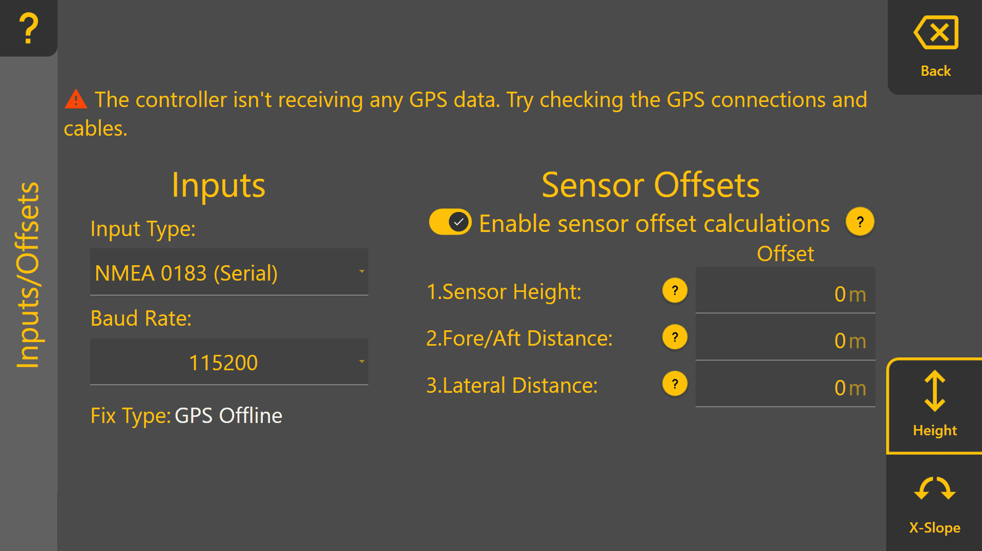](https://docs.t3rra.com/uploads/images/gallery/2026-06/RwJKnnpgFwCXgaut-image.png) Tap on the dropdown box below **Input Type** to view the different GNSS input options currently available. This dropdown will update with any StarFire or NMEA 2000 receivers currently connected, which are then displayed with either "SF" or "N2K" followed by the receiver serial number. Verify that each function ("Height" if using a single receiver, "Height 1" & "Height 2" if using tandem or dual receivers) has a Fix Type of RTK before proceeding.**Fix Type MUST be RTK for accurate automatic control operation** - lower accuracy fix types such as GPS only, Differential or Float RTK are not appropriate for accurate implement position control. Poor GNSS quality will affect machine positioning and automatic control performance.
##### **StarFire Example:** [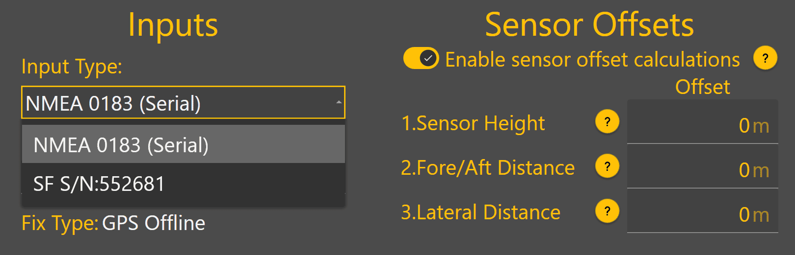](https://docs.t3rra.com/uploads/images/gallery/2025-08/ltW8hUiIHkgq00Wk-image.png) ##### **NMEA 2000 Example:** [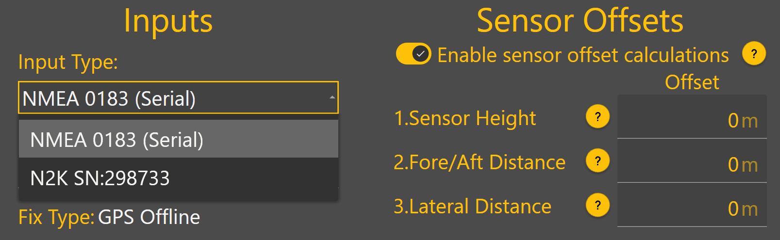](https://docs.t3rra.com/uploads/images/gallery/2025-08/EUaOC4R8oYjrLny5-image.png)Once the GNSS receiver has been selected, **Fix Type** should change from GPS Offline to another status to indicate the current GPS quality. If GPS Offline is still shown, the receiver may still be initialising.
### Sensor Offsets If using a GNSS receiver with **Level COMMAND** that is not capable of IMU-based terrain compensation, sensor offset calculations can be enabled. **Blade Width -** Enter the height of the GNSS receiver's measurement point above the cutting edge of the blade. Positive = Above the cutting edge Negative = Below the cutting edge **Fore/Aft Distance** - Enter the distance forward or backward from the cutting edge of the blade to the GNSS receiver centre point. Positive = Behind the cutting edge Negative = In front of the cutting edge **Lateral Distance** Enter the distance between the GNSS receiver centre point to the middle of the cutting edge of the blade. Positive = To the right side of the middle as if standing behind the scraper Negative = To the left side of the middle as if standing behind the scraper ##### Sensor Offsets Example: [](https://docs.t3rra.com/uploads/images/gallery/2025-08/G2QAsuovMLOuJ6Wk-image.png)In the example screenshot below, the GNSS receiver has been mounted: - 2 metres above the blade cutting edge - 0.5 metres behind the blade (away from the tractor) - 0.3 metres to the left of the middle of the blade (looking toward the rear of the scraper)Inputs / Offsets setup is now complete for profiles with only a height control function.
If using Height & X-Slope, Tandem receiver or dual receiver profiles, continue on to set up the second control function's inputs/offsets.
## Verifying GNSS Status & Health ### GPS Thresholds **GPS Thresholds** define the minimum GNSS performance requirements expected by **Level COMMAND**. These thresholds are used to determine when GNSS warnings should be generated and whether GNSS data quality is suitable for accurate automatic control. The default values supplied by T3RRA have been selected to provide reliable operation in most environments and should not normally require adjustment. Only modify these values if directed by T3RRA Support or if site-specific conditions require alternative settings. To access GPS Thresholds: 1. Return to the main **Level COMMAND** screen. 2. Press **More** on the right-hand side of the display. 3. Select **GPS Thresholds**. [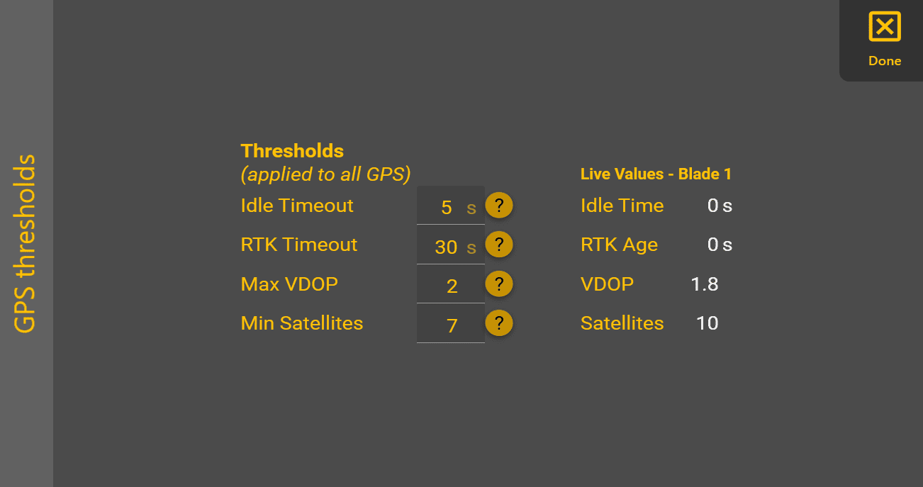](https://docs.t3rra.com/uploads/images/gallery/2025-04/JG9image.png) The **GPS Thresholds** screen allows the following values to be configured: #### Idle Timeout The maximum allowable period of time that GNSS data can stop being received before a warning is generated. #### RTK Timeout The maximum acceptable age of RTK correction data. If corrections exceed this age, GNSS accuracy may no longer be suitable for automatic control. #### Max VDOP The maximum allowable Vertical Dilution of Precision (VDOP). Lower VDOP values generally indicate better vertical positioning accuracy. A value below 2 is recommended for normal operation. #### Min Satellites The minimum number of satellites required before a warning is generated. Note that some receivers only report a maximum of 12 satellites even when additional satellites from multiple constellations are being used. This behaviour can be normal and depends on the receiver manufacturer. ### Live Values [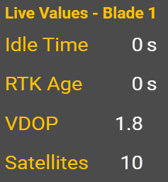](https://docs.t3rra.com/uploads/images/gallery/2025-04/9Afimage.png) The Live Values panel displays the current GNSS values being compared against the configured thresholds. During commissioning, verify that: - GNSS data is updating continuously. - RTK correction age remains within limits. - VDOP remains within the configured threshold. - Satellite count satisfies the minimum requirement. The Live Values panel provides a convenient method of confirming GNSS health during commissioning. For continuous monitoring during operation, GNSS information can also be displayed using the Widget Interface.Once GNSS receiver selection, sensor offsets and GPS Threshold verification have been completed, GNSS configuration is complete.
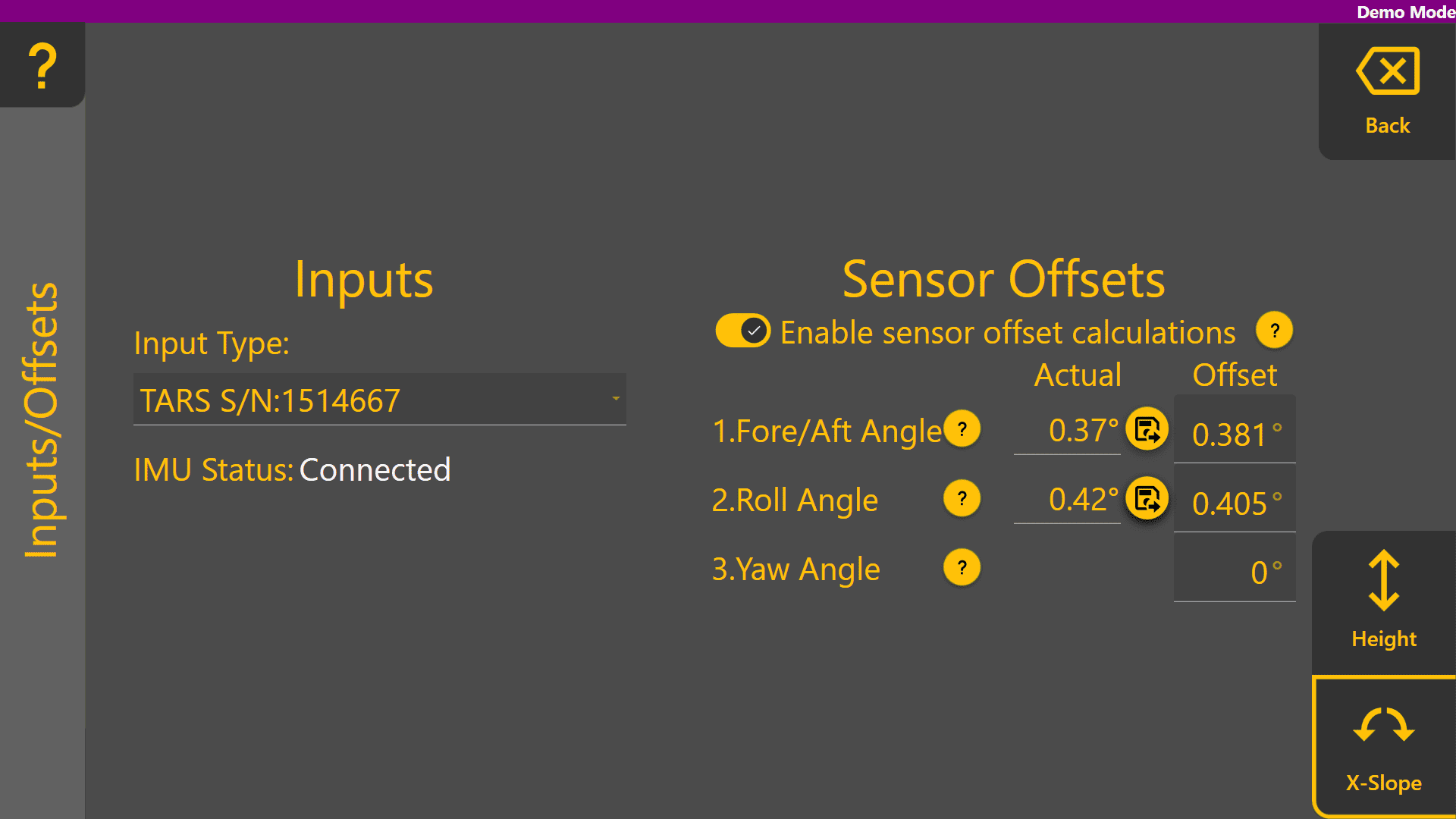
To get back to **COMMAND** Inputs set up, return to the **Level COMMAND** main page and press "**More**" at the right side of the screen > **COMMAND Settings** > **Inputs/Offsets**. To set up a secondary receiver for Height 2, i.e. Tandem implements or implements with dual receiver follow the process above for **Height 2** as well. ## X-Slope Input Configuration[](https://docs.t3rra.com/uploads/images/gallery/2025-08/U29nEhkS4ovruLO1-image.png) Some **COMMAND** machine profiles have a Tilt / X-slope control function intended for use with an IMU for blade tilt / x-slope angle feedback. Tap on the **Input Type** dropdown box to view currently connected IMU sensors, and select the desired input sensor. [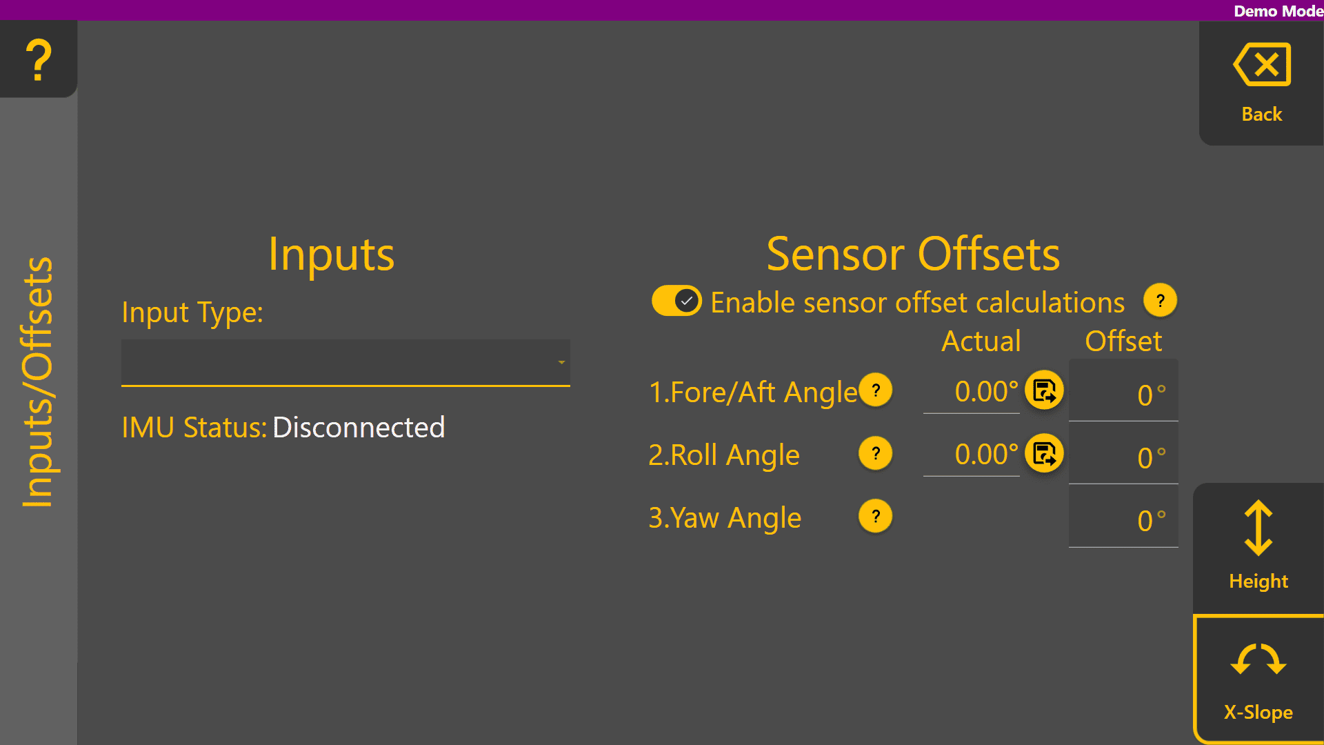](https://docs.t3rra.com/uploads/images/gallery/2025-08/63EJoyNEYjFIV7d6-image.png) Once selected, **IMU Status** will change to Connected. Additionally, the **Actual** values for **Fore/Aft Angle** and **Roll Angle** below **Sensor Offsets** will begin updating with the current angle of the selected IMU sensor. [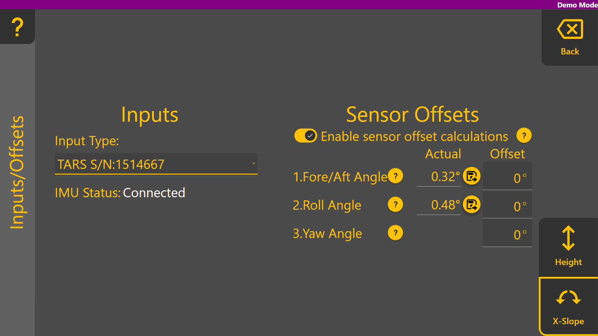](https://docs.t3rra.com/uploads/images/gallery/2025-08/pMuXmRqb4gLLYOX5-image.png) ### Accounting for IMU Mounting with Offsets [](https://docs.t3rra.com/uploads/images/gallery/2025-08/sUm6D1gBGCp6X7rq-icon-saveoffsets.png)In cases where the IMU sensor has not been mounted on the blade at a perfect 0 degree pitch and/or roll angle, the save offset buttons can be used to set the **Fore/Aft Angle** and **Roll Angle** offsets to the current angle reading. Before doing so, use equipment such as a spirit level, or a known level surface to ensure the blade is completely level. Once done, press the **Save** icons to set each of the two offset values to the current angles.Offsets are saved in the **COMMAND** ECU and only need to be changed if the position of the IMU sensor has changed, or if fitting the IMU to a different implement.
[](https://docs.t3rra.com/uploads/images/gallery/2025-08/cp9jWdhN1E23wBgz-image.png) Press "**Back**" to return to the COMMAND Settings Overview and continue on to **3.5 | Setting Valve Configurations**. # 3.5 | Configuring Valve Outputs [](https://docs.t3rra.com/uploads/images/gallery/2026-06/9uEsO89p0Nw2BAtu-image.png) The **Valve Configs** page is used to set up the control output interface for each control function. Appropriate signals of that interface type are then generated when automatic or manually controlling the implement. External joystick inputs are also configured on this page when making use of an analog or J1939 CANBUS joystick. [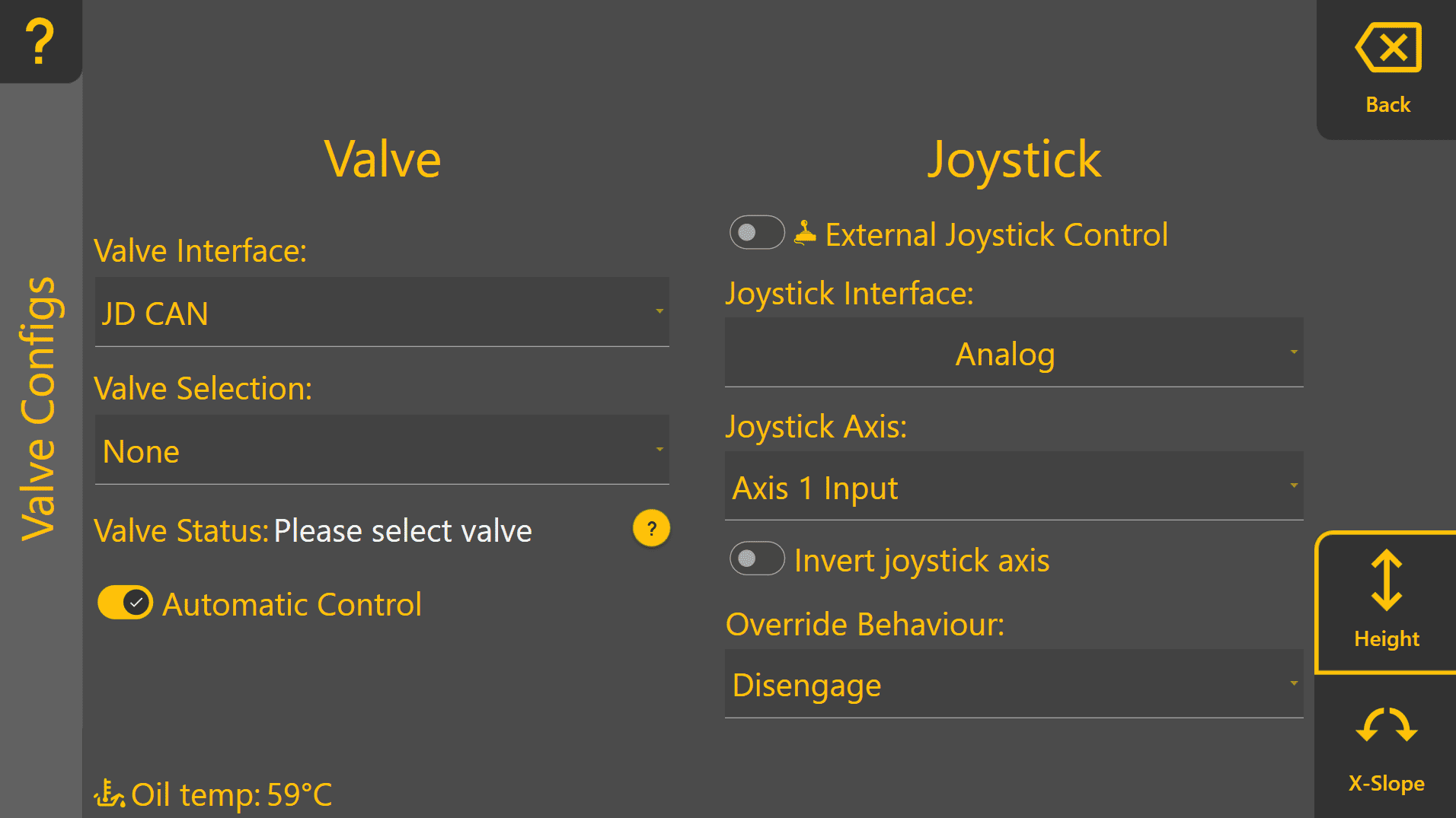](https://docs.t3rra.com/uploads/images/gallery/2026-06/OOdDozZSkAx6rcHT-image.png) At the bottom right corner of the screen, buttons will be shown if there are two available control functions. If using a Height control only machine profile, only the Height page is displayed. ## Selecting the Valve Interface Select the appropriate **Valve Interface** for the tractor, machine or external valves being used for that function. To begin with, set the desired **Valve Interface** type for the Height control function.Different **Valve Interface** selections display different **Valve Number** selections depending on how they work - for more information please see the section in the **COMMAND** manual.
[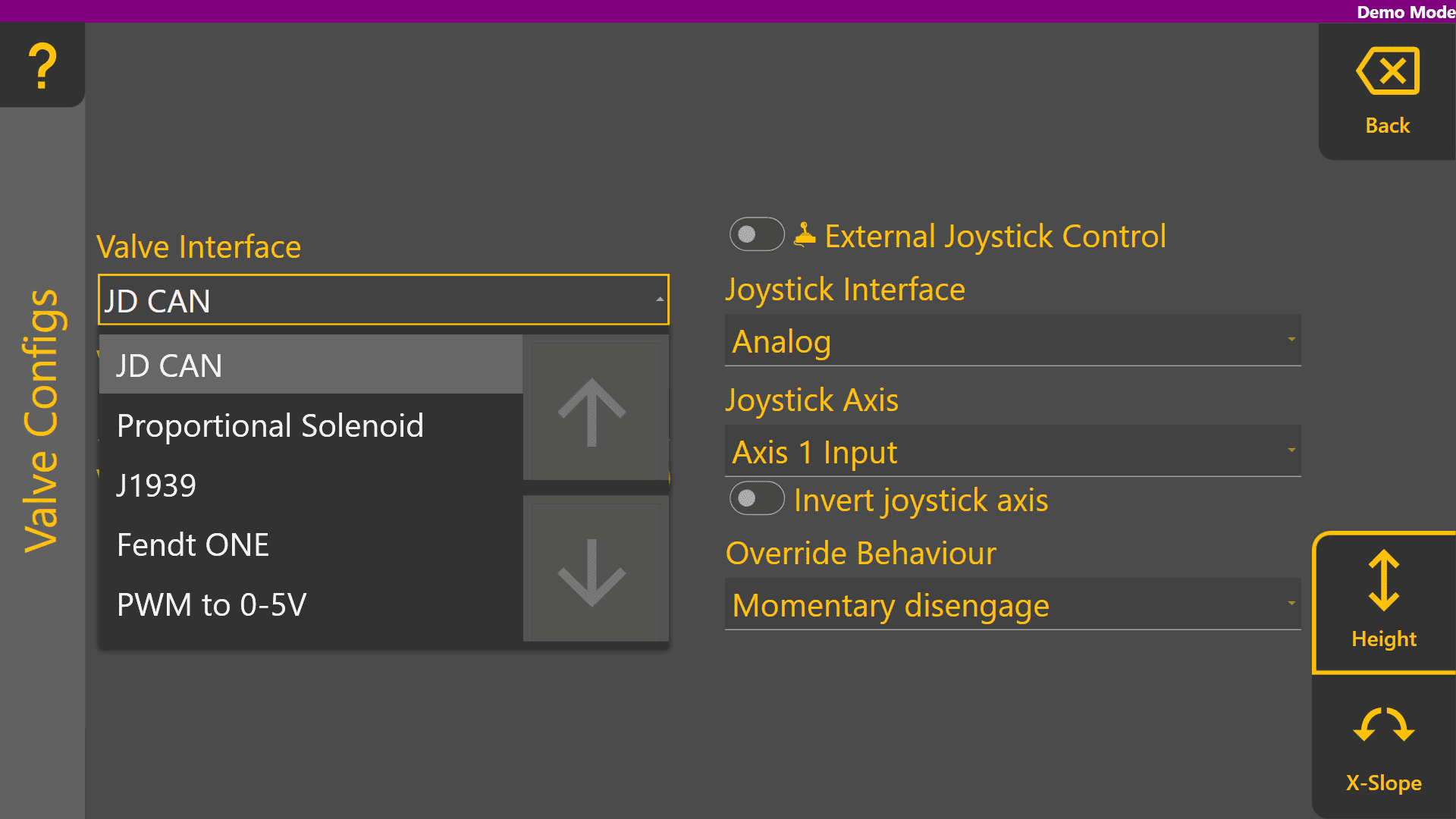](https://docs.t3rra.com/uploads/images/gallery/2025-08/CsyaCZMOhJtlnLtO-image.png) ## Selecting the Valve Number When selecting **Valve Interface** options like JD CAN, J1939 and Fendt ONE will only display valve numbers that have been detected on the ISOBUS or machine CANBUS. Below shows an example of the dropdown with the tractor switched off. [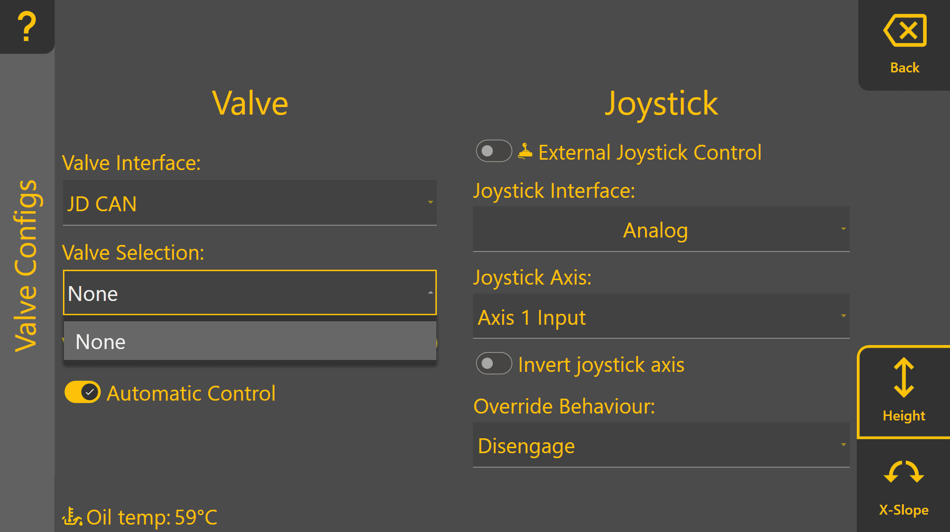](https://docs.t3rra.com/uploads/images/gallery/2026-06/vJVspAPIEaaHEpaz-image.png) Once detected on the ISOBUS or machine CANBUS, any available SCV / Remote / Auxiliary valve selections will be displayed in the **Valve Selection** list as shown: [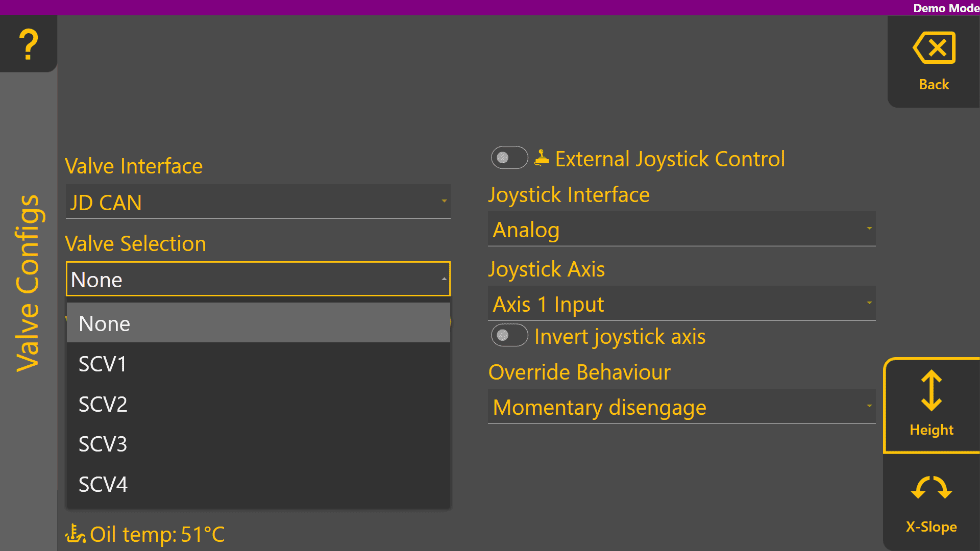](https://docs.t3rra.com/uploads/images/gallery/2025-08/Z1rpwjhhDtPDhwEv-image.png) Analog valve interfaces such as Proportional Solenoid and PWM to 0-5V always display all available **Valve Selection** options. Valve signals for these selections generally rely on harnessing to connect the outputs of the **COMMAND** ECU to the proportional solenoid or laser system inputs. [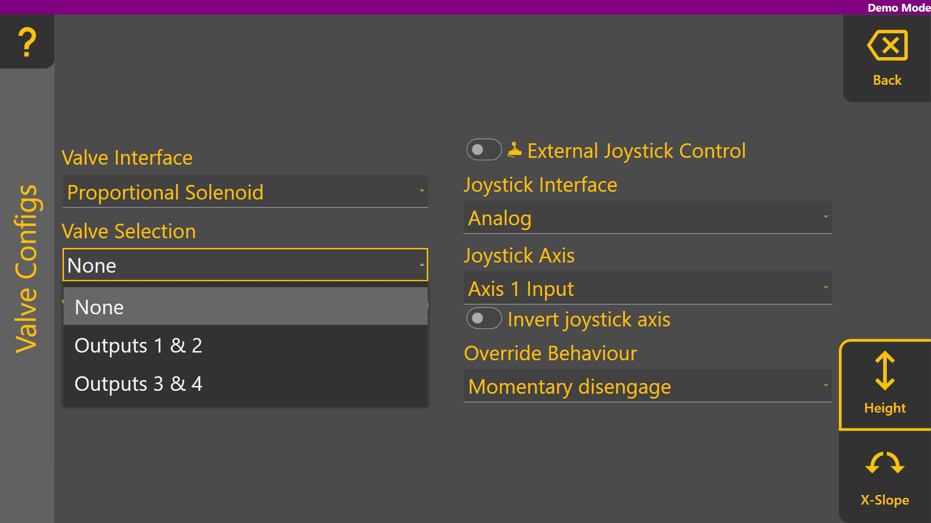](https://docs.t3rra.com/uploads/images/gallery/2025-08/wmEjkiD9uWjcxzmQ-image.png) ## Valve Status **Valve Status** provides information on the current status of the selected **Valve Interface** and **Valve Selection**. The table below explains each of the different possible valve statuses that may appear:| **Status** | **Description** |
| Valve Unavailable | The selected valve is not available for use. |
| Waiting for Manual SCV Input | Move the SCV lever corresponding to the selected SCV - this must be done when using John Deere tractors. |
| Short to Ground | An overload has been detected and the resistance between the valve signal output pin and ground is near-zero, holding the output low. |
| Short to Batt | An overload has been detected and the valve signal output pin is being fed power from another source holding the output high. |
| Open Load | A connection or valve issue has been detected, and the resistance between valve signal output pin is too high, indicating a broken wire or valve solenoid/coil. |
| SCVs Locked | The SCVs must be unlocked using the console SCV padlock button. |
| System Not Armed | The **COMMAND** Arm/Engage switch must be armed or re-armed. If the Arm/Engage switch is currently Off: - Switch the Arm/Engage switch to the middle position. If the Arm/Engage switch is currently in the middle position: - Switch the Arm/Engage switch to the OFF position, and then back to the middle position. |
| Ready | The selected valve is currently not active and the ECU is ready for automatic control or manual control commands for that function. |
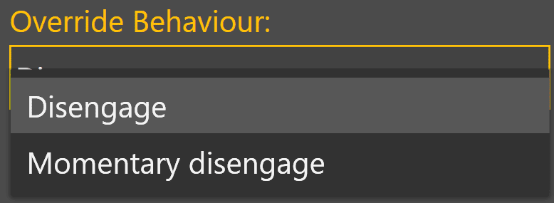
Regardless of **Override Behaviour** selection, **COMMAND** will always prioritise joystick/manual control signals over automatic control signals to maintain full operator control of the implement.
[](https://docs.t3rra.com/uploads/images/gallery/2026-06/nNQwrwdSyaPstVDg-image.png) #### Example Height Valve Configuration Page Below shows an example of a configuration using PWM to 0-5V **Valve Interface**, using the **T3H-V001** valve adapter on Output 1, with **Automatic Control** enabled. **External Joystick Control** has also been enabled for use with a J1939 CANBUS joystick, with the Y-axis controlling the Height function and will momentarily disengage automatic control when the joystick is moved. [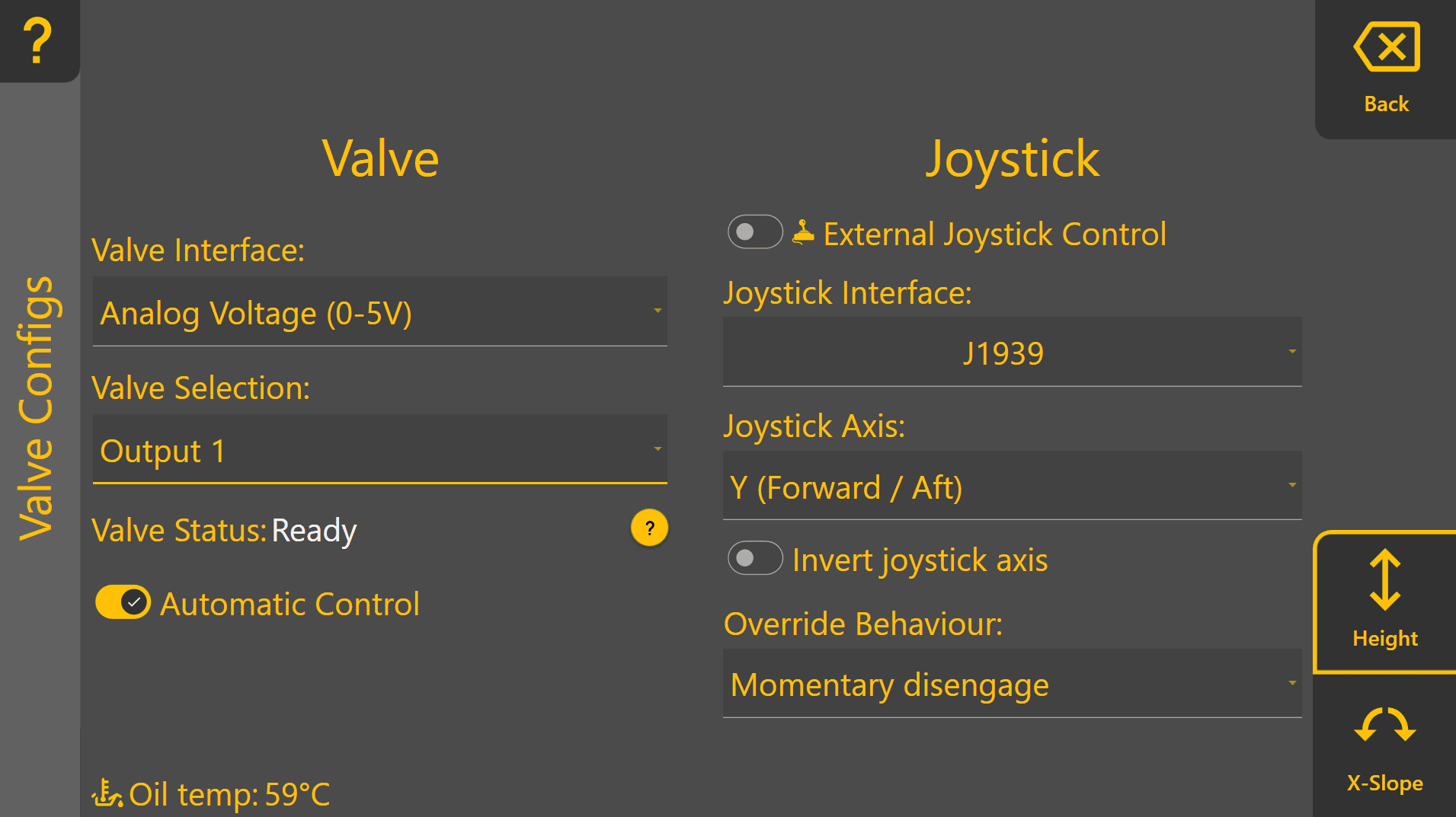](https://docs.t3rra.com/uploads/images/gallery/2026-06/J3NTkoYgKZNqd3Va-image.png) #### Example X-Slope Valve Configuration Page Swapping over to the X-Slope function using the bottom right button, an example configuration shown below is set up to use PWM to 0-5V **Valve Interface**, using the T3H-V001 adapter on Output 2. X-Slope is enabled for automatic control, and also has External Joystick Control enabled for use with a J1939 CANBUS joystick on the X-axis, momentarily disengaging when the operator moves the joystick. [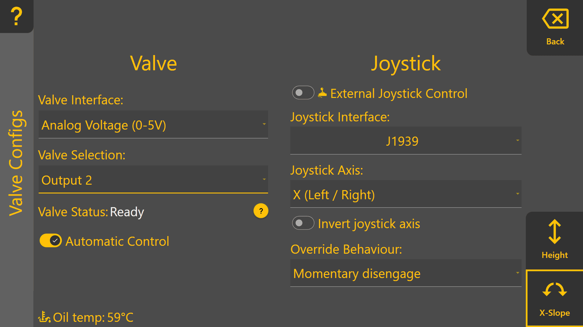](https://docs.t3rra.com/uploads/images/gallery/2026-06/8qfvbowzlQLf2rcz-image.png) Press "**Back**" to return to the COMMAND Settings Overview page and continue on to **3.6 | Valve Threshold Calibration**. # 3.6 | Valve Threshold Calibration Valve Threshold Calibration establishes the minimum and maximum hydraulic outputs used by Automatic Control. Correct calibration ensures the implement can move smoothly for small corrections while still achieving full operating speed when required. Access the **COMMAND** valve calibration page by going to: **More** > **COMMAND Settings** > **Valve Cals**. - **Minimum Threshold (Min %)** determines the lowest output that reliably opens the hydraulic valve. - **Maximum Threshold (Max %)** limits the highest output available to Automatic Control. [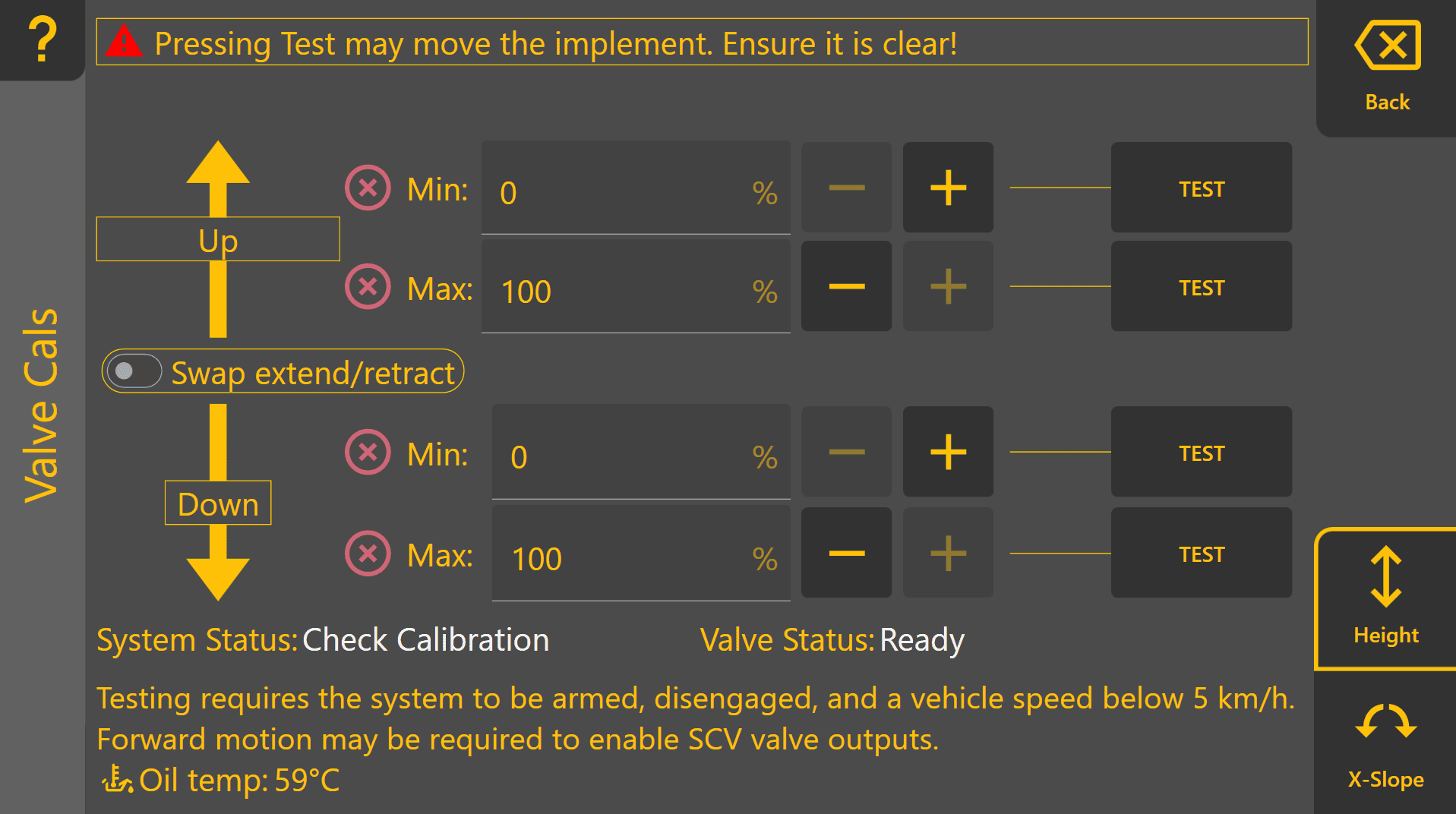](https://docs.t3rra.com/uploads/images/gallery/2026-06/PaQ5HIB45kQbxGS5-image.png) ## Calibration ProcedureThe **COMMAND** ECU will not request movement of the implement unless the user has pressed one of the test buttons and is holding the engage button.
1. Select the function and direction to calibrate. 2. Press **TEST** and hold the machine **ENGAGE** button when instructed. 3. Increase **Min. %** until the implement begins moving consistently at a very slow speed, e.g. about 1 centimetre per second. 4. Adjust **Max. %** as required: - For proportional solenoids, limit output to approximately **1800 mA**. - Reduce further if lower maximum implement speed is desired. 5. Repeat for all active directions and functions. #### Calibration Test Buttons The "+", "−" and "TEST" buttons are used during the calibration process to incrementally increase or reduce a given threshold, which can then be tested using the process described in the next section. #### Calibration Progress Icons This[](https://docs.t3rra.com/uploads/images/gallery/2025-08/8R3Nua9ds9TqSVa6-icon-uncalibrated.png) icon indicates that a value has not been calibrated yet. All minimum and maximum values for all active functions must be calibrated before performing automatic control. This [](https://docs.t3rra.com/uploads/images/gallery/2025-08/PdI75CypPWpfqpjF-icon-calibrated.png) icon indicates that a value has been calibrated. Once all min and max values display this icon, the function has been successfully calibrated.Ticks next to Min or Max values mean that the test button was pressed, but **do not indicate a correctly calibrated function**.
#### Example for Completed Height Function [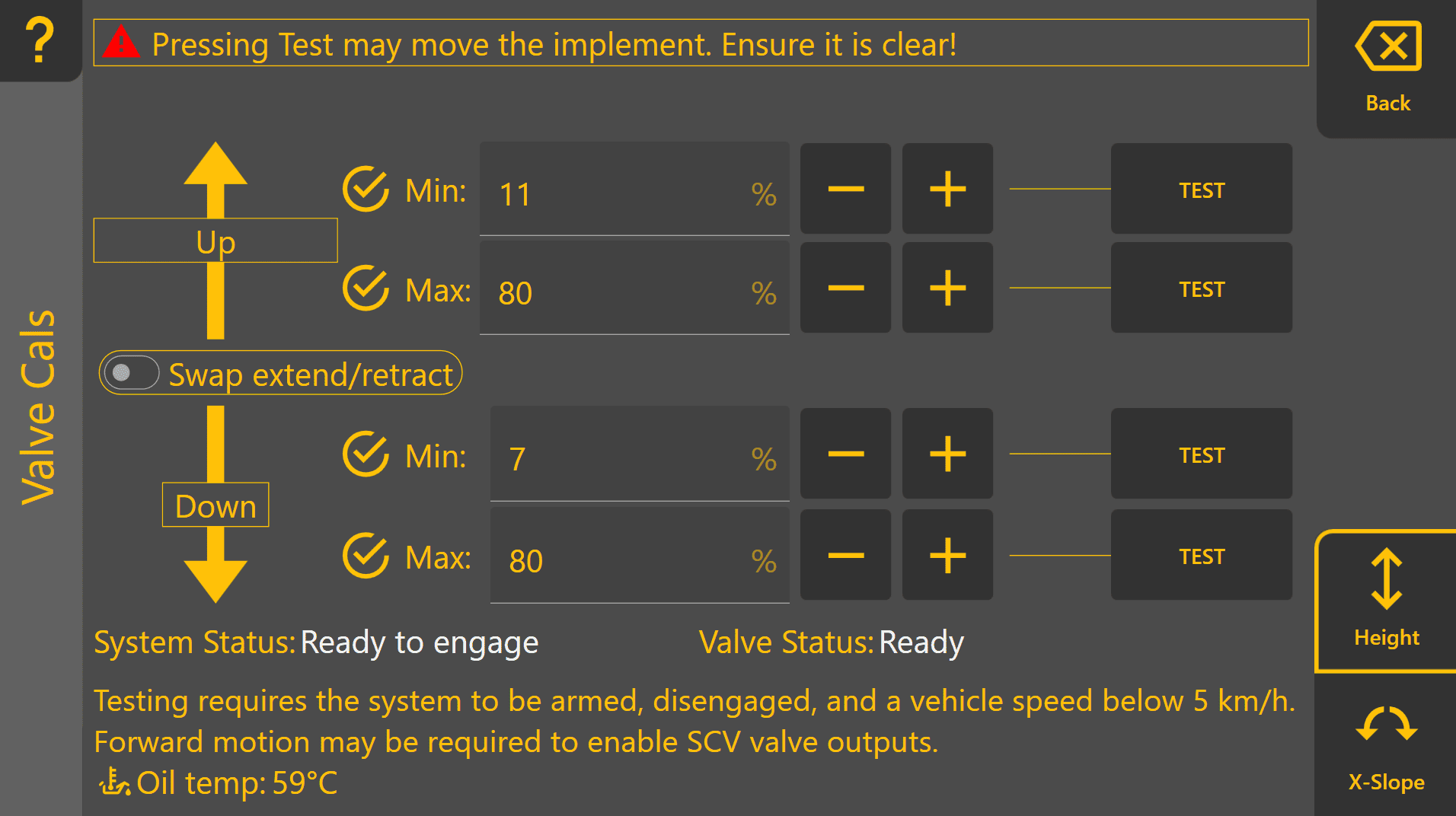](https://docs.t3rra.com/uploads/images/gallery/2026-06/I7RtWIj5rfmViFuw-image.png) #### Example for Completed X-Slope Function [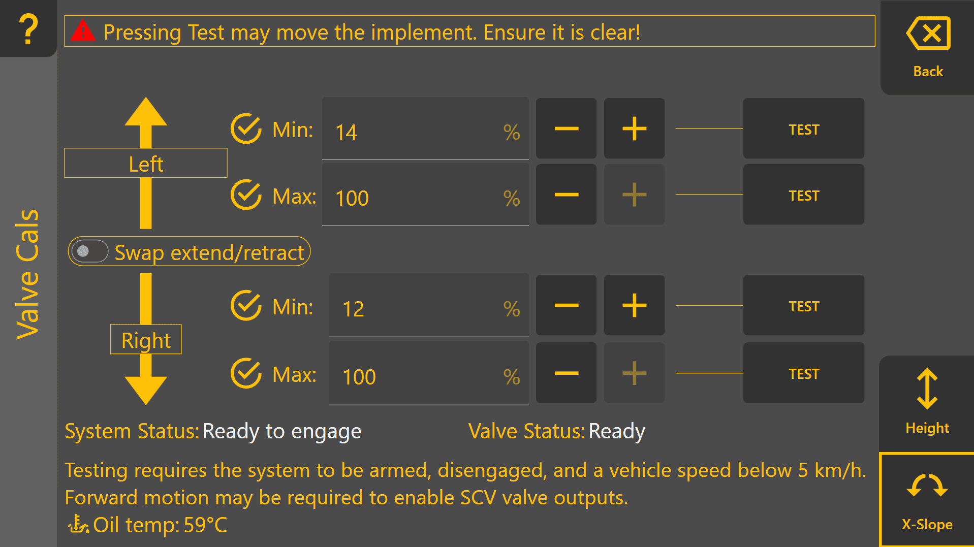](https://docs.t3rra.com/uploads/images/gallery/2026-06/OFVWGhCz3tIa1DHP-image.png) ## Verification Verify that: - Implement movement begins smoothly when Min % is tested. - No excessive delay or valve chatter occurs. - Full-speed movement is available when Max % is tested without hydraulic instability. - All calibration indicators show as complete before commissioning proceeds. Continue on to **3.7 | Cylinder Ratio Calibration**. # 3.7 | Cylinder Ratio Calibration [](https://docs.t3rra.com/uploads/images/gallery/2026-06/5zeMCboP04mWmytu-image.png) ## Overview Cylinder Ratio Calibration compensates for differences in implement movement speeds between opposing control directions. Hydraulic systems rarely move at identical speeds in both directions. Differences in cylinder geometry, implement weight, hydraulic flow characteristics, machine design and gravity can all influence the speed at which the implement moves. For elevation control, the implement may raise more slowly than it lowers due to implement weight and hydraulic loading. For cross-slope control, left and right tilt movements may also occur at slightly different rates due to cylinder geometry and hydraulic system characteristics. Cylinder Ratio Calibration measures the time taken to move the implement through its full range of motion in each direction and automatically calculates a correction ratio used by Automatic Control. ## Calibration Procedure ### Elevation (Raise / Lower) 1. [](https://docs.t3rra.com/uploads/images/gallery/2026-06/IxHpBIMj7B62bvjT-image.png) Position the implement at its lowest operating position. 2. Press **Start** in the **Up** section. 3. Immediately raise the implement at full manual control speed until maximum height is reached. 4. Press **Stop** when maximum height is reached. 5. Press **Start** in the **Down** section. [](https://docs.t3rra.com/uploads/images/gallery/2026-06/EppZUOHuvADh1yjU-image.png) 6. Immediately lower the implement at full manual control speed until minimum height is reached - do not make contact with the ground, stop the implement before it does. 7. Press **Stop** when minimum height is reached. 8. Press **Calc** to generate the Elevation Cylinder Ratio. [](https://docs.t3rra.com/uploads/images/gallery/2026-06/sIj48Eq9pE9pUKxW-image.png) ### Cross-Slope (Left / Right) 1. Position the implement at one end of its available tilt range. 2. Press **Start Left** or **Start Right** as appropriate. 3. Immediately move the implement at full manual control speed until the opposite end of travel is reached. 4. Press **Stop** when the limit of travel is reached. 5. Repeat for the opposite direction. 6. Press **Calc** to generate the Cross-Slope Cylinder Ratio. [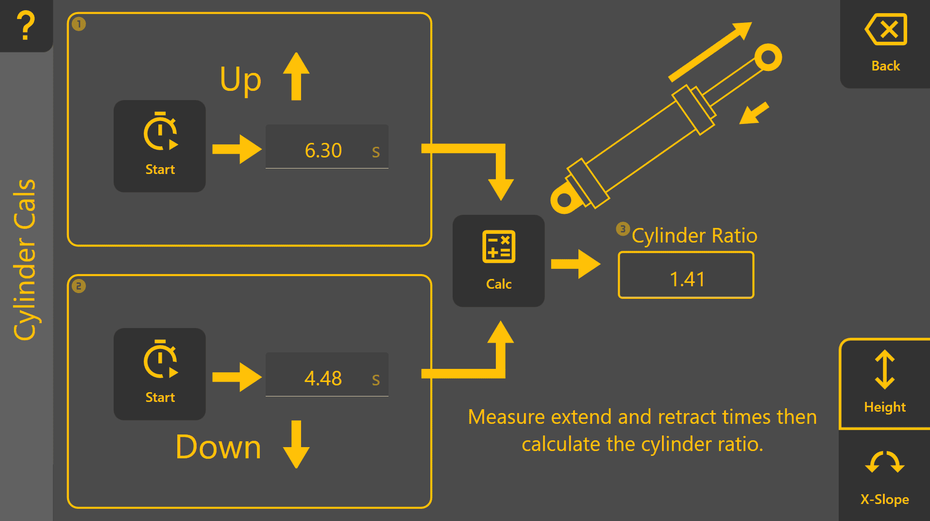](https://docs.t3rra.com/uploads/images/gallery/2026-06/GT9vVqtTUYqtT9FB-image.png) [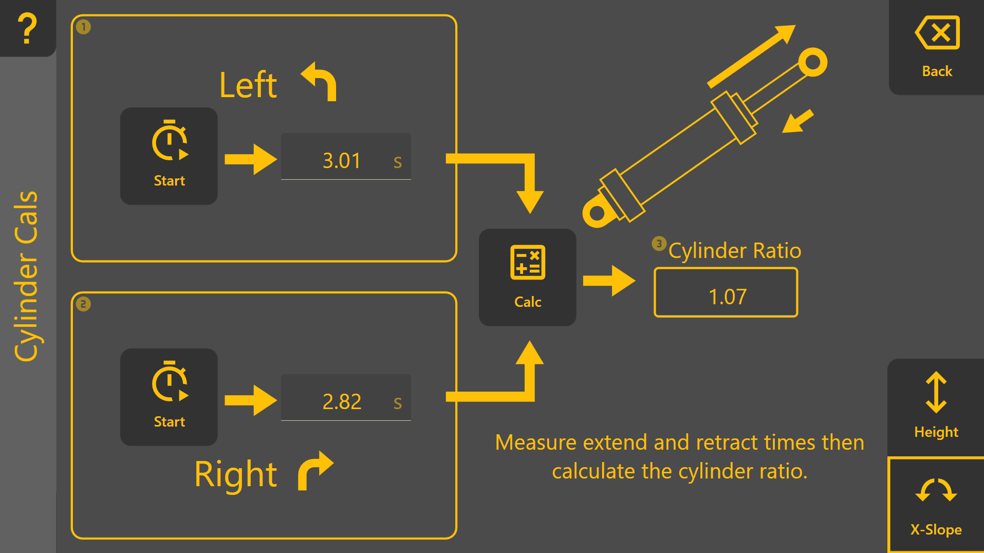](https://docs.t3rra.com/uploads/images/gallery/2026-06/5PTJF1pNvnHJ0YSR-image.png) ## Verification After calibration: - Implement movements should respond consistently in both directions during Automatic Control. - Neither direction should appear noticeably slower or more aggressive than the opposite direction. - If hydraulic components, cylinders, valves or plumbing are modified, cylinder calibration should be repeated. Continue to **3.8 | Tuning Automatic Implement Control**. # 3.8 | Tuning Automatic Implement Control The purpose of tuning is to achieve stable, accurate Automatic Control that follows the design surface smoothly without excessive lag or oscillation. The Tuning page provides the controls and feedback required to optimise control performance. To find the tuning page from the Apply View, press **More > COMMAND Settings > Tuning**. ## Tracking and Acquisition Behaviour Once Automatic Control is engaged, the **COMMAND** ECU adjusts its control strategy according to the current error between the implement and the design surface.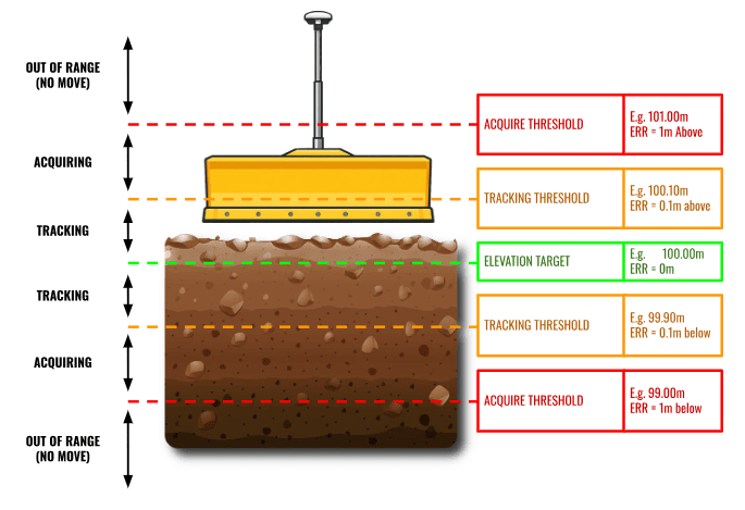 *Automatic Control transitions between Acquisition, Tracking and Out-of-Range regions according to the current error between the implement and the design surface.*The default **Tracking Threshold** and **Acquire Threshold** values are suitable for almost all applications and should not normally require adjustment. Modification of these parameters is generally not recommended.
Three operating regions are used: #### Tracking Region (e.g. < 10cm Error) The Tracking Region is the area immediately surrounding the design surface. This region provides the highest grading accuracy and is where the implement should spend most of its operating time. When the current error is within the configured **Tracking Threshold**, **COMMAND** continuously adjusts hydraulic output using its tracking control algorithm to accurately maintain the implement on grade. By default, the tracking threshold is 10cm for height functions, and 10 degrees for x-slope functions. Within the Tracking Region, hydraulic output is continuously adjusted between the calibrated minimum and maximum valve thresholds according to the current control error. #### Acquisition Region (e.g. > 10cm but < 1m Error) The Acquisition Region exists between the **Tracking Threshold** and **Acquire Threshold**. When the implement is outside the Tracking Region but remains within the **Acquire Threshold**, **COMMAND** prioritises returning the implement to the Tracking Region as quickly as possible. During acquisition, the ECU commands hydraulic output at the calibrated **Max %** threshold until the implement re-enters the Tracking Region. Once inside the Tracking Region, control automatically transitions back to normal tracking. #### Out of Range (e.g. > 1m Error) If the current error exceeds the configured **Acquire Threshold,** the implement is considered too far from the design surface for Automatic Control to operate safely or effectively. In this condition, **COMMAND** does not command hydraulic movement. This prevents large or unexpected hydraulic movements when the implement is significantly displaced from the design surface. The operator should manually reposition the implement closer to the design surface before Automatic Control resumes operation. ## Before Tuning [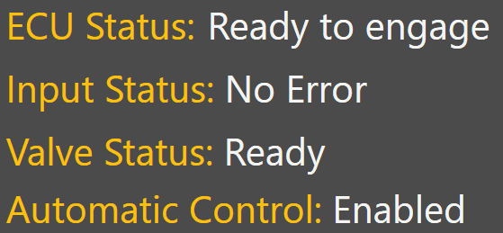](https://docs.t3rra.com/uploads/images/gallery/2025-08/xW68g0hjkQbD8asC-image.png) Before tuning, verify the following diagnostic indicators report normal operating status: - **COMMAND** ECU Status - Input Status - Valve Status - Automatic Control Diagnostics Any active faults or invalid status conditions should be corrected before tuning begins. ## Tuning Procedure ## [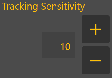](https://docs.t3rra.com/uploads/images/gallery/2025-08/3gRxv00W73mIGAJ2-image.png) Tuning should always be performed under normal working conditions using the same machine speed, hydraulic flow settings and operating practices that will be used during production work. **Level COMMAND** currently provides a single tuning parameter called **Tracking Sensitivity**. The objective is to achieve stable control while maintaining accurate tracking of the target surface. 1. Load a suitable project or design surface. 2. Engage Automatic Control. 3. Perform several passes under normal operating conditions. 4. Observe implement behaviour and control performance. 5. Adjust **Tracking Sensitivity** as required. 6. Repeat until the implement follows the target smoothly without excessive lag or oscillation. During normal grading, the implement should enter the Acquisition Region only briefly before returning to the Tracking Region, where it should remain for most of the grading operation. If the implement spends excessive time acquiring, overshoots repeatedly or oscillates around the target surface, further tuning may be required.| Adjustment | Typical Effect |
|---|---|
| Increase Tracking Sensitivity | Faster response, more aggressive control, increased risk of overshoot or oscillation. |
| Decrease Tracking Sensitivity | Slower response, smoother control, increased risk of lag and persistent tracking error. |
Correct [valve calibration](https://docs.t3rra.com/link/1147#bkmrk-minimum-threshold-%28m)—particularly the **Min** **%** thresholds—is essential before tuning begins. Incorrect **Min** **%** calibration can produce symptoms similar to incorrect **Tracking Sensitivity** and cannot be corrected through tuning alone.
#### Tracking Sensitivity Too Low - Implement responds slowly - **Current Error** remains visible for extended periods - Blade struggles to reach target grade - **DPF** remains elevated due to persistent tracking error Recommended Adjustment > Increase **Tracking Sensitivity**. [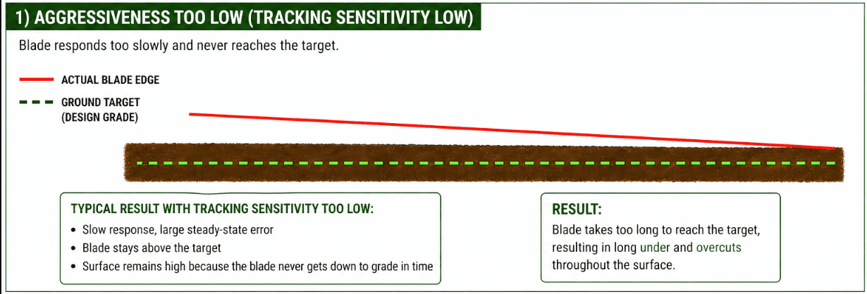](https://docs.t3rra.com/uploads/images/gallery/2026-06/zCOFaLwX6CtHlDpj-image.png) #### Tracking Sensitivity Too High - Implement reacts aggressively - Blade overshoots the target surface - Oscillation develops - **DPF** increases due to instability and overcorrection Reduce **Tracking Sensitivity**. Recommended Adjustment > Reduce **Tracking Sensitivity**. [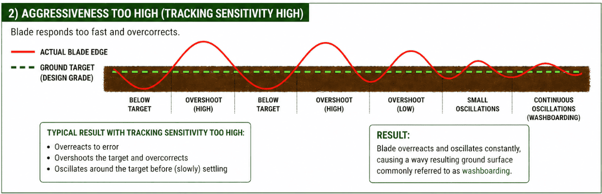](https://docs.t3rra.com/uploads/images/gallery/2026-06/k91zV9bYz3fcuqJi-image.png) Once Automatic Control is performing at an acceptable level, continue on to **3.9 | Validating System Operation**. # 3.9 | Validating System Operation ## Status Validation Checks| **Item** | **Expected Result** |
|---|---|
| ECU Status | Connected and operating normally |
| GNSS Status | Fixed RTK solution |
| Position Accuracy | Within expected limits |
| Inertial Sensors | Reporting valid data |
| Valve Outputs | Available and responding |
| Machine Configuration | Correct implement selected |
| Active Faults | None present |
| Validation Item | Pass |
|---|---|
| ECU communicating successfully | ☐ |
| GNSS selected and stable with RTK Fix | ☐ |
| X-Slope sensor angle values updating correctly | ☐ |
| Hydraulic outputs verified | ☐ |
| Cylinder calibration completed | ☐ |
| Automatic Control engages correctly | ☐ |
| Control direction verified | ☐ |
| Tracking Sensitivity tuned | ☐ |
| Grade tracking validated | ☐ |
| Automatic Control performance acceptable | ☐ |
| No active faults present | ☐ |
Once all validation checks have been completed successfully and Automatic Control performance has been verified, the machine is ready for operator training and production use.
Dealer installation and commissioning is now complete. Continue to **Section 4 | Operator Quick Start** for guidance on day-to-day operation of **Level COMMAND**.