2 | System Overview
Level COMMAND is an integrated machine guidance and control system designed to provide real-time positioning, terrain visualisation, and machine control functionality for supported earthmoving equipment.
- 2.1 | System Architecture
- 2.2 | Supported Machine Configurations (Profiles)
- 2.3 | Positioning & Sensor Requirements
- 2.4 | Hydraulic & Vehicle Interfaces
- 2.5 | System Components
2.1 | System Architecture
Level COMMAND continuously determines the machine's position, compares it to the design surface and calculates the implement movement required to achieve the desired grade.
Theory of Operation
Level COMMAND is a closed-loop terrain-control operating environment that continuously compares the machine’s measured terrain position against the active design surface or plane in order to determine the required implement movement.
The system operates together with the COMMAND hardware platform, GNSS receivers, hydraulic interfaces, machine sensors, and operator inputs to provide terrain guidance and automatic implement control.
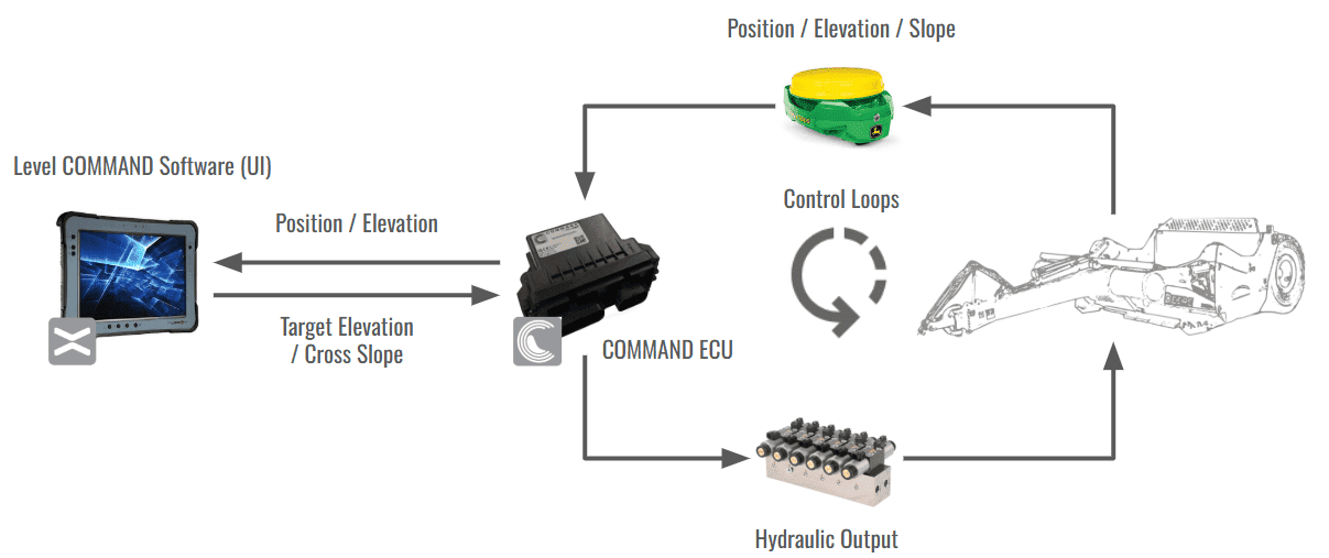
During operation, Level COMMAND continuously processes:
- GNSS position data
- Machine and receiver offsets
- Active design surfaces or planes
- Machine configuration information
- Operator-applied offsets and limits
- Vehicle movement and speed information
Using this information, the system calculates target elevations and control corrections which are transmitted to the COMMAND ECU for hydraulic or vehicle interface control.
The operator remains responsible for supervising machine behaviour and safe operation at all times.
Position & Elevation Processing
GNSS receivers are mounted at known positions relative to the controlled implement. Level COMMAND applies configured machine and receiver offsets to calculate the position of the controlled point relative to the terrain surface.
Using the calculated controlled-point position, the system determines:
- Current Height
- Design Height
- Target Height
- Cross-slope or tilt requirements where applicable
These values are used to determine the required implement correction relative to the active design surface or control mode.
Configured machine geometry and positional offsets are applied before hydraulic commands are transmitted to the COMMAND ECU to ensure implement movement corresponds correctly to the controlled point position.
Predictive Control (Look Ahead)
Hydraulic systems and machine movement introduce a delay between terrain measurement and implement response.
To improve grading accuracy during movement, the system uses predictive positioning behaviour referred to as Look Ahead.
Look Ahead estimates the future position of the controlled point based on current machine speed and configurable control response timing. Target elevations are then calculated ahead of the machine’s current position to reduce tracking lag and improve terrain-following performance.
Look Ahead settings may be adjusted during commissioning and advanced diagnostics procedures.
Blade Shift & Control Limits
Material movement requirements may exceed the desired cut or fill amount achievable in a single grading pass.
Blade Shift allows operators to temporarily offset the target elevation relative to the active design surface without modifying the underlying project data.
Additional control limits may also be applied to restrict:
- Maximum cut depth
- Maximum fill height
- Cross-slope correction
- Hydraulic response behaviour
- Automatic control engagement conditions
These limits assist in maintaining stable machine behaviour and predictable terrain outcomes during automatic control operation.
Off-Surface Behaviour
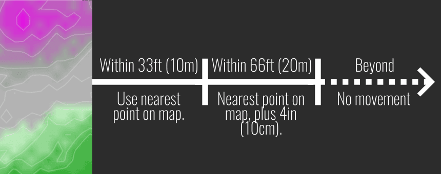
Automatic control operation requires valid design surface data. If the machine moves outside the available design surface area, the system may suspend automatic control movement commands until valid surface data becomes available again. Automatic control resumes as the implement approaches the design surface again.
This behaviour prevents unintended implement movement when operating beyond the active design boundary.
Manual & Automatic Control Modes
Level COMMAND supports both manual and automatic implement control operation.
Manual Control Mode
When automatic control is Disengaged, hydraulic movement remains under direct operator control using tractor SCVs, joysticks, or other configured control inputs.
In Manual Control Mode, the system continues to display terrain, project, and elevation information but does not actively control hydraulic outputs.
Armed State
When the system is Armed, the COMMAND ECU is enabled and prepared to assume automatic control once engagement conditions are satisfied.
While Armed, manual hydraulic control remains available to the operator. The Armed state allows the system to monitor positioning and control conditions while preventing automatic hydraulic actuation until automatic control is Engaged.
Automatic Control Mode
When automatic control is Engaged, the system continuously calculates implement corrections relative to the active design surface or plane.
The COMMAND ECU then controls hydraulic outputs using:
- Current terrain position
- Target elevation
- Cross-slope targets where applicable
- Control calibration parameters
- Tracking sensitivity settings
- Acquire and tracking thresholds
Depending on machine configuration, manual hydraulic input may temporarily override automatic control or disengage automatic control operation. Automatic control may be disengaged at any time using the configured disengagement controls or Arm/Engage switch.
2.2 | Supported Machine Configurations (Profiles)
Level COMMAND supports multiple machine configurations depending on machine type, hydraulic capability, installed hardware, and available automatic control functions.
Each machine configuration defines the supported automatic control functions and compatible machine architecture for the connected implement.
Available machine configurations may vary depending on installed hardware, software licensing, and machine compatibility.
Single Scraper — Height
The Single Scraper — Height profile provides automatic height control for supported single-channel scraper configurations.
Typical applications include:
- landforming,
- scraper levelling,
- and general earthmoving operations.
Single Scraper — Height & XSlope
The Single Scraper — Height & XSlope profile provides automatic height and Cross-Slope control for supported dual-channel scraper configurations.
Typical applications include:
- precision grading,
- drainage shaping,
- and controlled Cross-Slope operations.
This configuration requires compatible Cross-Slope sensing hardware.
Single Ditcher — Height
The Single Ditcher — Height profile provides automatic height control for supported ditching and channel-forming implements.
Typical applications include:
- drainage channel construction,
- irrigation works,
- and ditch grading operations.
Future Configuration Support
Additional machine configurations and automatic control capabilities may become available in future Level COMMAND releases depending on machine compatibility and installed hardware support.
2.3 | Positioning & Sensor Requirements
Level COMMAND uses GNSS positioning data, machine geometry information, and implement orientation feedback to calculate target elevations and automatic control corrections.
Depending on machine configuration and enabled functions, the system may require:
- RTK GNSS positioning,
- vehicle heading information,
- Cross-Slope feedback,
- machine geometry offsets,
- and compatible COMMAND hardware interfaces.
GNSS Positioning Requirements
Level COMMAND receives GNSS positioning information through the COMMAND ECU.
GNSS positioning data is used to determine machine location, implement elevation, and terrain position relative to the active design surface or plane.
Automatic control operation requires stable RTK-quality positioning suitable for precision terrain-control applications.
If GNSS quality falls outside configured operating limits, automatic control operation may be restricted or disengaged.
Heading Information
Vehicle heading information is used to determine machine movement direction relative to the active terrain design.
Heading information is typically supplied through GNSS data received by the COMMAND ECU.
If dedicated heading information is unavailable, the system may determine movement direction using positional change during vehicle movement.
Cross-Slope Feedback
Machine configurations supporting automatic Cross-Slope control require compatible implement roll-angle feedback.
Cross-Slope feedback is used to determine implement orientation relative to the active design surface and commanded Cross-Slope target.
Supported Cross-Slope feedback sources currently include:
- T3RRA TARS IMU systems,
- and compatible StarFire internal roll-angle sensors.
Invalid or unstable Cross-Slope data may prevent automatic control engagement or cause automatic control disengagement.
Machine Geometry & Offsets
Level COMMAND uses configurable machine geometry information to calculate implement position relative to the GNSS receiver location.
Depending on machine configuration, offsets may include:
- sensor height offset,
- lateral offset,
- and fore/aft offset.
Incorrect machine geometry configuration may result in inaccurate implement positioning or automatic control behaviour.
Sensor Stability & Control Protection
The COMMAND hardware platform continuously monitors positioning and sensor information during operation.
Automatic control engagement may be prevented, or automatic control may disengage, if:
- GNSS positioning becomes invalid,
- sensor information becomes unstable,
- positioning changes exceed configured operating limits,
- hydraulic faults are detected,
- or operating conditions fall outside configured control thresholds.
These protections assist in maintaining predictable implement behaviour during automatic control operation.
2.4 | Hydraulic & Vehicle Interfaces
The COMMAND hardware platform supports multiple hydraulic and vehicle interface methods depending on machine configuration, installed COMMAND hardware, and enabled automatic control functions.
These interfaces allow COMMAND to control implement movement and monitor machine information during automatic control.
Hydraulic Control Interfaces
Depending on machine configuration, COMMAND may support:
- single-channel height control,
- dual-channel height and Cross-Slope control,
- and implement-specific hydraulic functions.
Supported hydraulic interface methods may include:
- Selectable Control Valves (SCVs) / auxiliary control valves,
- proportional solenoid valves,
- and ratiometric load sensing proportional valves.
Hydraulic outputs are used by COMMAND to change implement position during automatic control based on elevation and Cross-Slope targets provided by Level COMMAND.
Vehicle Data Interfaces
COMMAND may receive vehicle and machine information using compatible communication interfaces.
Supported interface methods may include:
- J1939 vehicle communication,
- CANBUS communication,
- and supported OEM machine data interfaces.
Available machine data may include:
- vehicle speed,
- hydraulic state information,
- and supported machine sensor information.
Available interface methods may vary depending on installed COMMAND hardware and machine compatibility.
Manual Hydraulic Operation
Manual hydraulic operation remains available whether automatic control is Engaged or Disengaged.
Depending on machine configuration, manual implement control may be performed using:
- tractor SCVs,
- joysticks,
- external hydraulic controls,
- or OEM machine hydraulic controls.
The Armed state enables the COMMAND ECU while preventing automatic hydraulic actuation until automatic control is Engaged.
Disarming the COMMAND ECU will disengage automatic control and disable joystick inputs connected directly through COMMAND. Tractor-level SCV lever and joystick operation remain unaffected.
2.5 | System Components
A Level COMMAND system consists of multiple hardware and software components depending on machine configuration and enabled automatic control functions.
Required Components
The following components are required for normal Level COMMAND operation.
COMMAND ECU
The COMMAND ECU provides hydraulic control, machine interfacing, sensor monitoring, and automatic control management.
The ECU communicates with Level COMMAND and connected machine systems during operation.
GNSS Receiver System
A compatible RTK-capable GNSS receiver system is required for machine positioning and automatic control.
Supported receiver compatibility may vary depending on installed COMMAND hardware and machine configuration.
Operator Display Device
Level COMMAND operates on a compatible display device used for:
- project management
- terrain visualisation
- diagnostics
- and operator interaction
The display device communicates with the COMMAND ECU during operation.
Level COMMAND is primarily deployed on ruggedised RuggON tablet platforms including the PX501 and SOL7 due to their environmental durability, sunlight readability, and suitability for machine-control applications.
Hydraulic Control Hardware
Compatible hydraulic control valve hardware is required for automatic implement movement.
Depending on machine configuration, hydraulic interfaces may include:
- SCVs / auxiliary control valves
- proportional solenoid valves
- and ratiometric load sensing proportional valves
Optional Components
Additional components may be installed depending on machine configuration and enabled functionality.
Cross-Slope Sensors
Cross-Slope-capable configurations require compatible implement roll-angle feedback sensors.
Supported Cross-Slope feedback sources currently include:
- T3RRA TARS IMU systems
- and compatible StarFire internal roll-angle sensors
Additional Operator Controls
Optional operator control devices may include:
- External Engage switch,
- Joystick controls
Vehicle Data Interfaces
Supported machine configurations may include additional vehicle communication interfaces such as:
- ISOBUS
- J1939