# 7.3 | CNH Direct Connect (AFS Connect / PLM Intelligence)
**Applicable to:**
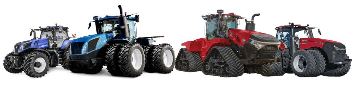
Case IH / New Holland tractors with AFS Connect or PLM Intelligence systems.
[](https://docs.t3rra.com/uploads/images/gallery/2025-07/HBhMQQ3eVQl7QHWG-image.png)
## Connection Method
**[](https://docs.t3rra.com/uploads/images/gallery/2025-06/R3uuiKBzm8bcb1Oq-image.png)COMMAND** can control Case & New Holland rear tractor valve (EHR) systems through the use of a **T3H-V001** COMMAND Legacy Output Adapter.
##
##
##
## Installation Steps
[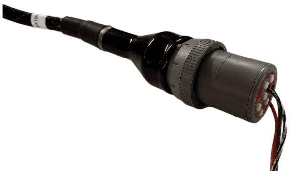](https://docs.t3rra.com/uploads/images/gallery/2025-07/ywPFWUQXnCahBXUF-image.png)The Case / New Holland tractor connection for analog control signal inputs via the **T3H-V001** adapter are generally found in one of three locations depending on tractor mode:
1\. Locate the tractor SCV signal input connector:
\- Fuse compartment
\- Behind driver seat
\- Under cab exterior (4WD models)
2\. Connect the **T3H-V001** adapter to the tractor connection.
3\. Connect the **T3H-V001** adapter to the **T3H-C002** harness.
## Tractor Valve Configuration
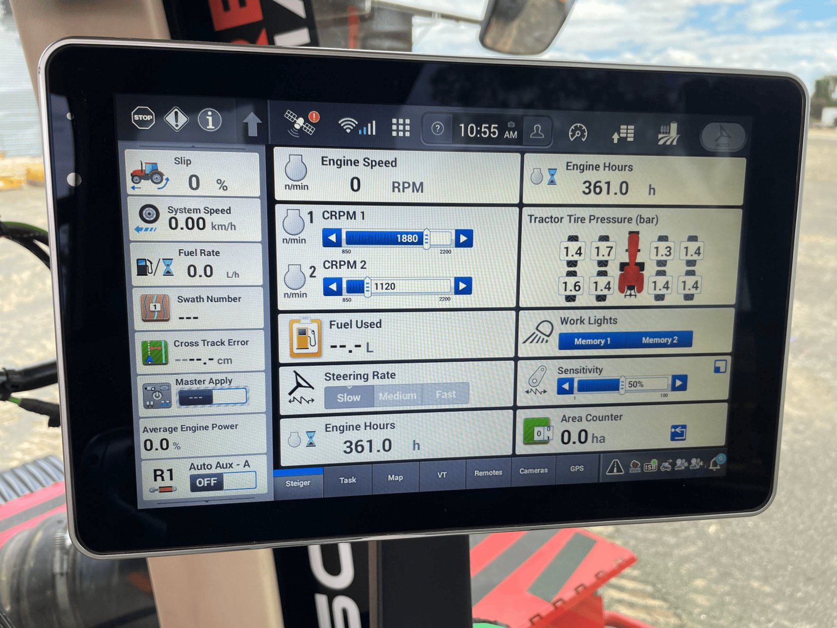
1\. After completing the physical connection, the system must be configured on the tractor armrest display.
[](https://docs.t3rra.com/uploads/images/gallery/2025-06/6citV3azhXn8CjJm-image.png)
2\. Ensure that a new implement profile has been created for use with the scraper, or that the currently selected profile is
appropriate.
[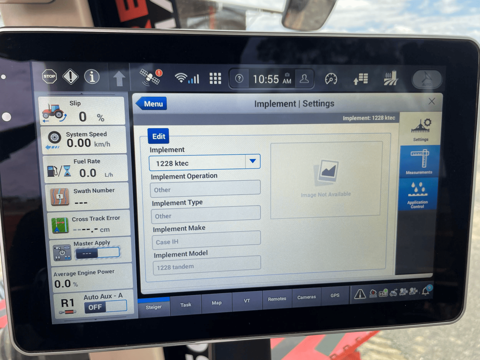](https://docs.t3rra.com/uploads/images/gallery/2025-06/KB1fxjEPXkB2epeJ-image.png)
3\. Open the “Remotes” settings tab to display remote valve configuration.
[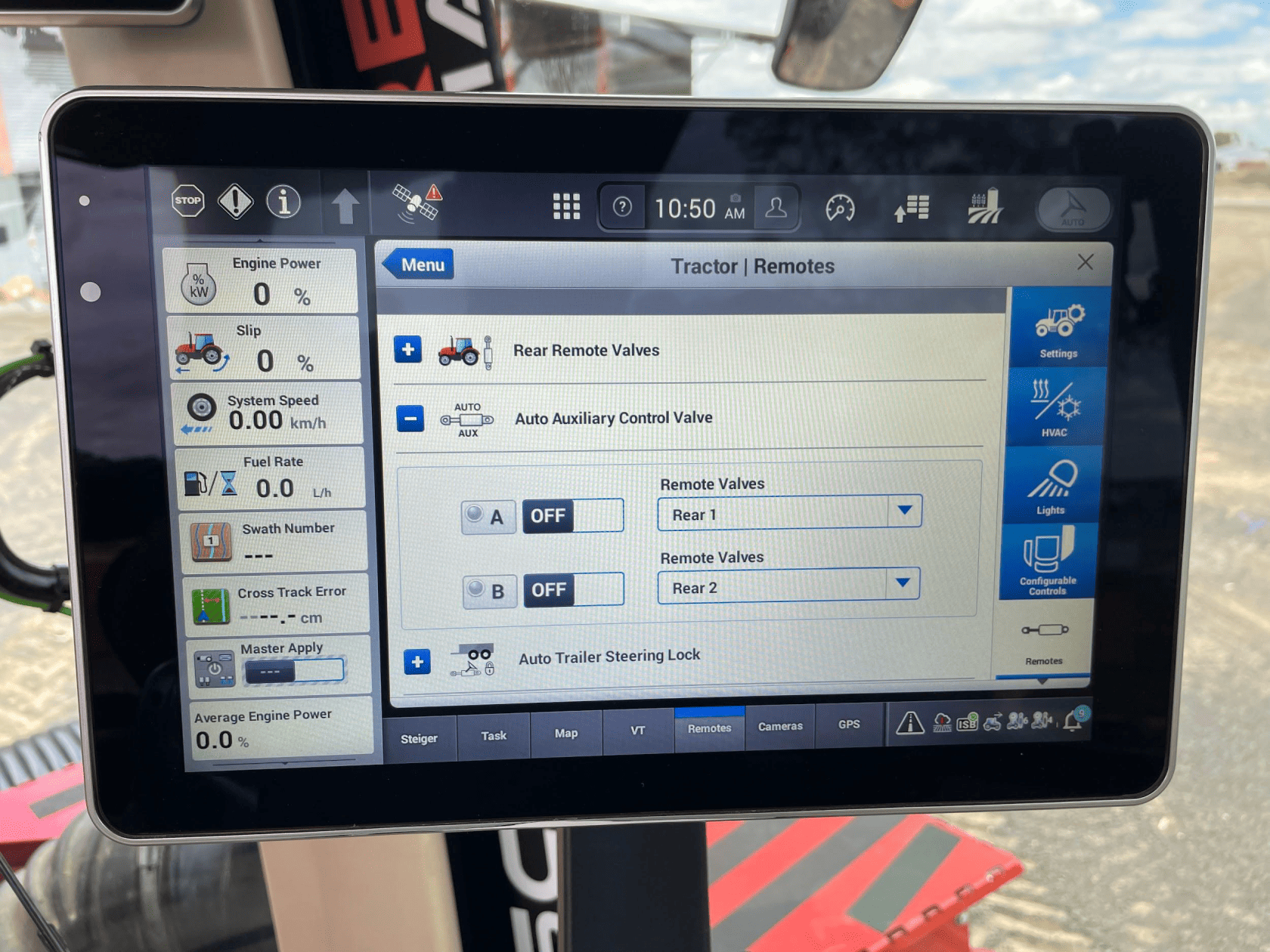](https://docs.t3rra.com/uploads/images/gallery/2025-06/4H2xNOyVIHbWMUJF-image.png)
4\. Set the desired remote valve outputs at the back of the tractor to the desired function (A or B).
[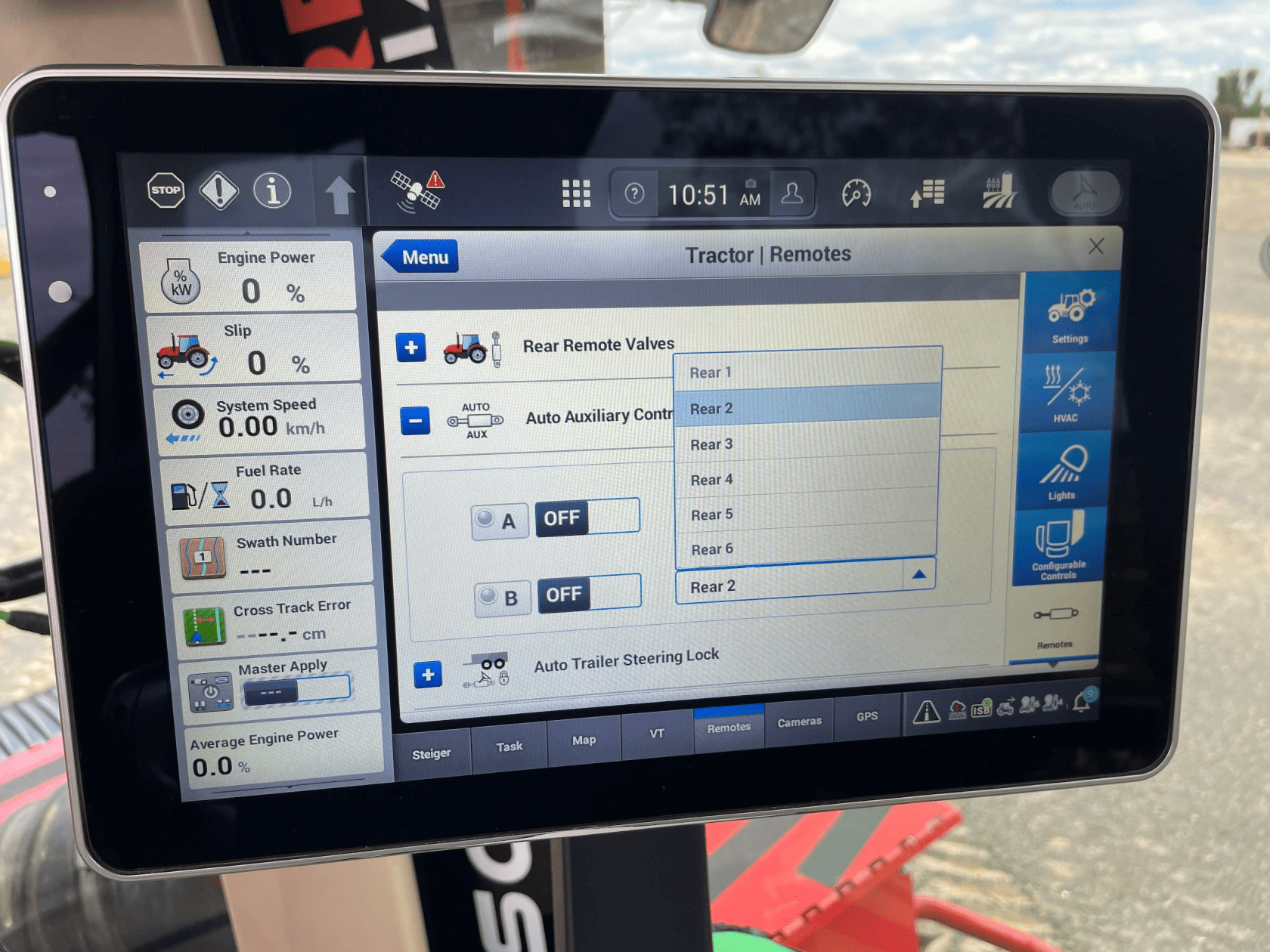](https://docs.t3rra.com/uploads/images/gallery/2025-06/m6PNSJkMFxWwK435-image.png)
**NOTE**: The remote valves selected for A and B should be matched to the valve connections at the back of the tractor pictured
below. We recommend setting auxiliary valve A to remote valve “Rear 1”, and setting auxiliary valve B to remote valve “Rear 2”,
which will configure remote valves 1 and 2 at the back of the tractor for use with iGrade.
[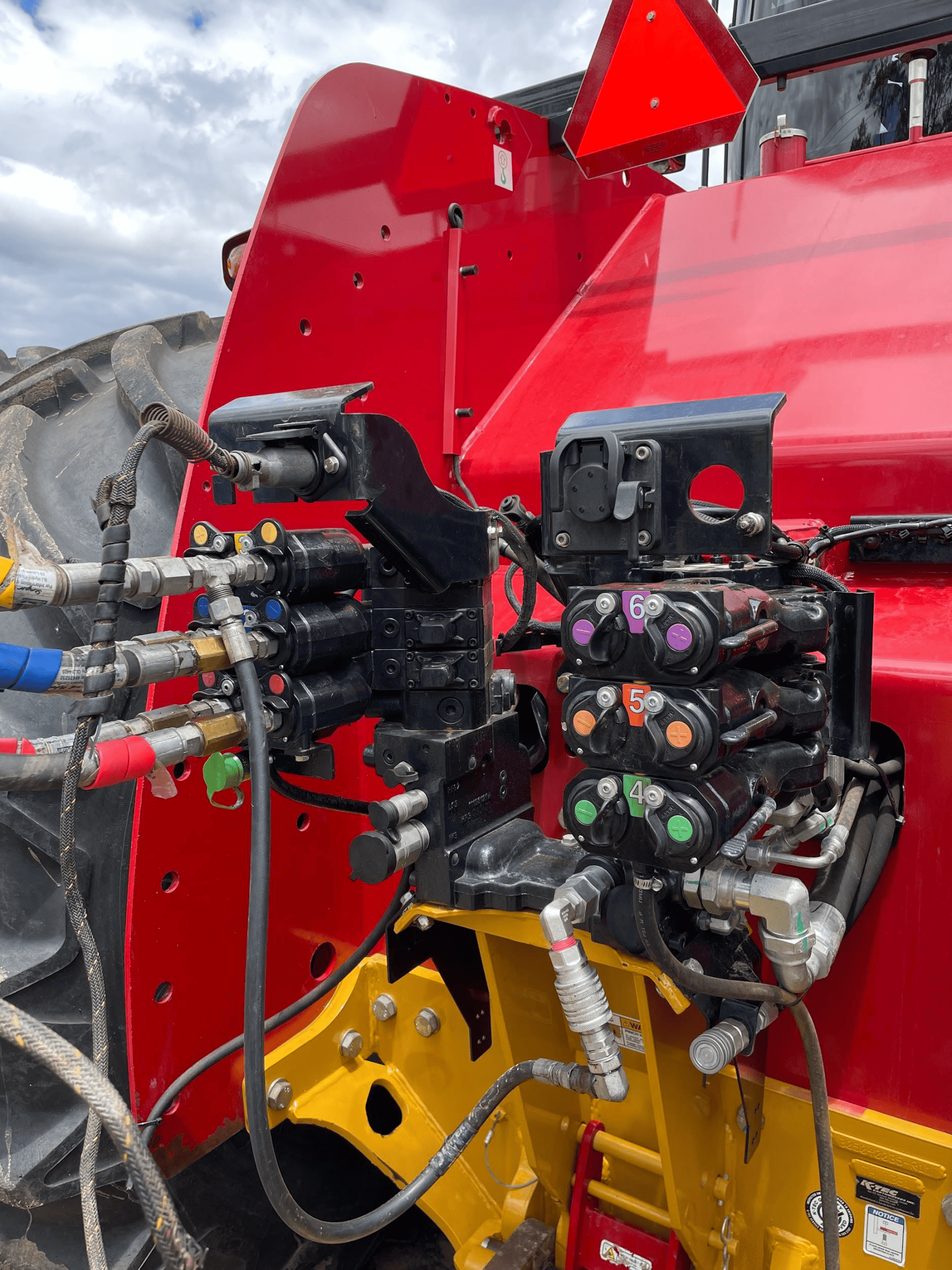](https://docs.t3rra.com/uploads/images/gallery/2025-06/uy2QGbE152OG4u48-image.png)
5\. Once the remote valves on the tractor have been set to the desired auxiliary function, the machine should now be fully
configured and ready for use. In order to engage auxiliary control, the user must ensure that the Auto Auxiliary Control
Valves A & B have been turned on in the relevant area on the “Remotes” page.
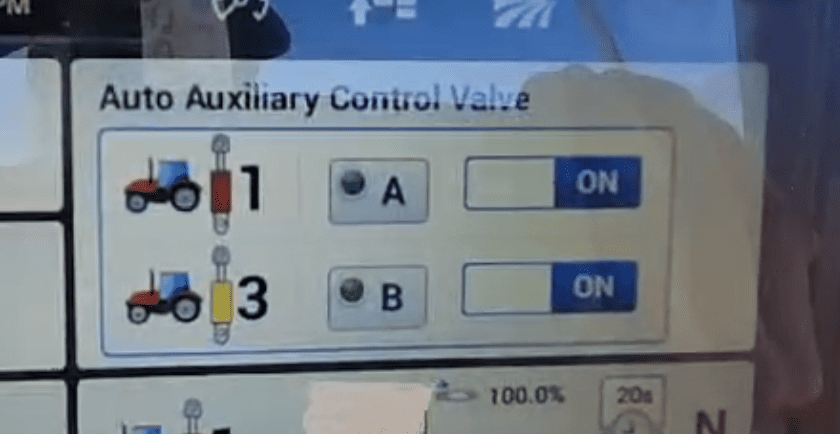
6\. The “Auto Auxiliary Control Valve” can be accessed either by the hydraulic cylinder shortcut next to the display
navigation dial on the armrest, or by adding the menu to the display home page. Once this menu is accessed, turn
either or both required function to the on position and briefly push the lever until it clicks, similar to detenting a John
Deere tractor but the lever with not remain in place. Once both A and B lights are solid green, the tractor is ready to
accept 0-5V signals through the implement interface 6-pin connector.
[](https://docs.t3rra.com/uploads/images/gallery/2025-06/IpXIImajv9x3G1CJ-image.png)
## Operation Notes
**COMMAND** interfaces with the Case / New Holland tractor valves by sending analog signals to the integrated valve controller, commanding either port A or port B flow of two of the rear tractor SCVs (For AFS Connect models any SCV can be linked to either of the two analog inputs).
To operate the SCVs in automatic control mode, the user first needs to arm one or both of the configured auto SCVs by toggling the Auto Auxiliary Control Valve toggles to ON.
Then, either push the respective SCV lever forward into the detent position or press the respective SCV button in front of the levers. This will cause the A and/or B LEDs on the pro 1200 screen to change to solid green, indicating the valves are ready for automatic control.
Levers can be moved manually, which will override manual control and once let go, automatic control will resume. To disable automatic control, pull the respective SCV lever until it clicks. The A or B LED on the pro 1200 screen should now begin flashing, meaning that automatic control is paused until the operator resumes by pushing the lever to detent or pressing the SCV button again.
**IMPORTANT**: Moving the SCV lever alone will NOT disengage AUTO mode in modern case tractors, so movements based on any current valve signals will continue. Always keep this in mind during operation.
For more information on configuring **COMMAND** for use with Case / New Holland auxiliary rear valve control inputs, please refer to the **Level COMMAND** Manual.