5.2 | Electronic Control Unit (ECU) Installation
ECU Mounting Overview
The COMMAND ECU can be installed in one of three locations depending on the tractor and application:
1. In-cab (preferred)
2. Behind rear cab panel
3. Rear of tractor near ISOBUS connection
The selected mounting location will determine harness routing and connection layout. Please follow the relevant installation instructions based on the selected mounting location.
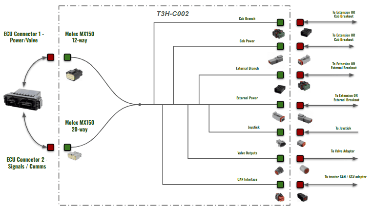
Connections Overview
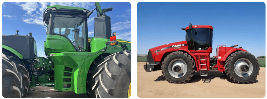
Mounting Locations
Select the mounting location based on available space, environmental exposure, and ease of harness routing.
In-Cab (Preferred)
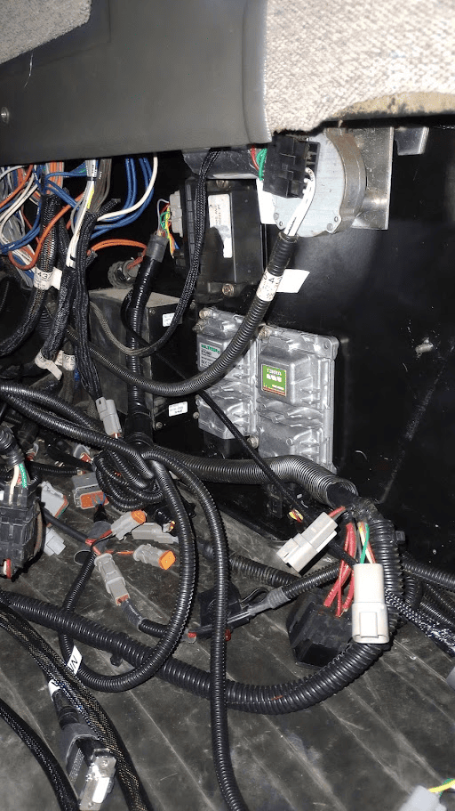
Mounting in the cab of the tractor is the preferred option, as it best protects the ECU and harnessing from the elements. Mounting the ECU in-cab is best suited to tractors with paneling, compartments or normally covered cab walls with enough room to mount the ECU.
Being mounted in cab will provide access to the following for the T3H-C002 ECU breakout harness:
- Power via convenience plug or power strip
- Arm/Engage Switch
- Tablet
- 4-way ISOBUS connection if present in cab harnessing
- Diagnostic ports for tractor CAN access
- Joystick
- Valve output connections to Case EHR inputs or JD legacy proportional inputs
Cabling will need to be run outside of the cab if:
- Proportional solenoid or Danfoss PVE valve cabling must be run out to an external valve block
The photos above show some suitable mounting locations found in older Case tractor models, where an ECU can either be magnet mounted or Rivnut mounted depending on preference.
Rear Panel Mounting
In situations where the cab doesn't have enough suitable space for mounting the ECU and neatening the harnessing, the ECU can be mounted at the back of the tractor behind rear paneling if enough space is available.
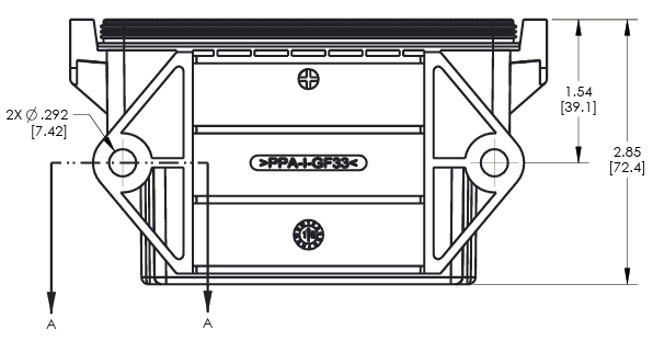
The ECU should be mounted with enough space for connection and disconnection of the breakout harness, which will also require some space itself when tying up and neatening the T3H-C002 harness.
The ECU can be mounted in much the same way as in-cab - see following pages for information on ECU dimensions and mounting methods.
Rear Breakaway Mounting
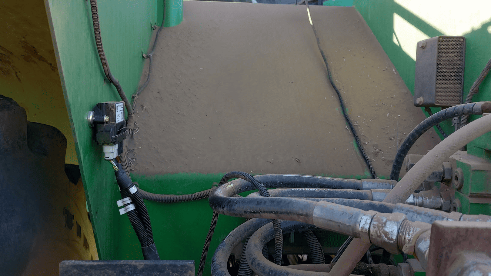
If there isn't enough space present in the cab or behind the rear paneling of the cab, then there is generally plenty of space to be able to mount the controller at the rear of the tractor near or next to the ISOBUS implement breakaway connector.
If mounting here, magnets are not recommended as there is a lot of potential for dirt and rocks to knock the ECU. Custom bracketing is recommended when installing the controller at the rear of the tractor to help shield the ECU from dirt and rocks, and to also provide a reliably secure mounting connection through the use of bolts and nylon-lock nuts.
Mounting Methods
Magnets
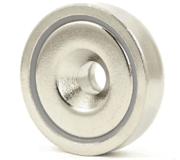
Mounting with strong neodymium magnets can provide a quick and robust method of mounting the COMMAND ECU.
Neodymium magnets with a countersunk centre hole of 7mm diameter along with 7mm fasteners should be used.
Rivnuts
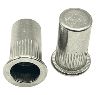
Mounting with Rivnuts is another effective way of securing the ECU to the inner or outer wall of the tractor.
Care should be taken to drill an appropriately sized hole of the Rivnut, then use the expansion tool and fasten the ECU securely.
Dimensions Drawing
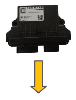
Mounting orientation
The ECU must be mounted with electrical connectors facing downward to prevent moisture and dirt ingress. Do not mount the ECU with the connectors facing upward or to the side as moisture or dirt may accumulate and cause corrosion and/or connection issues.
Connecting the ECU Breakout Harness
Once the ECU is mounted securely in place:
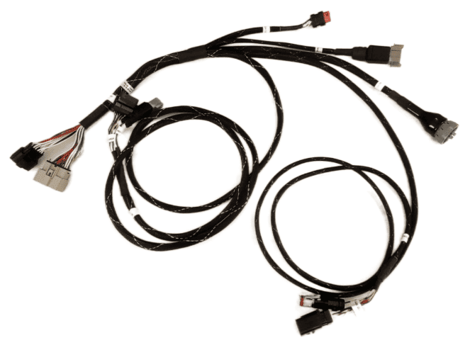
- Connect the T3H-C002 to the ECU with the black and beige paired ECU plugs shown below.
- Push each plug in until a click is felt.
- Gently pull on the plug to ensure that it has mated correctly.
To unplug the ECU connection later, press down on the tab at the top of the connectors (facing toward you with the ECU mounted in the direction specified above) and pull the plug downward away from the ECU.

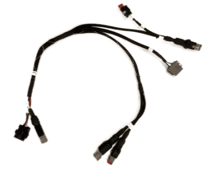
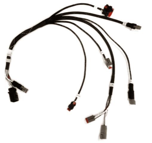
Once the T3H-C002 ECU breakout harness has been connected to the ECU, connections to the external and cab breakout harnesses need to be made. The T3H-C005 exterior breakout harness is designed to be positioned at the rear of the tractor, while the T3H-C006 cab breakout harness is designed to be positioned inside the tractor cab.
T3H-C002 - ECU Breakout Harness
T3H-C005 - Exterior Breakout Harness
T3H-C006 - Cab Breakout Harness
Connecting the Exterior and Cab Breakout Harnesses
The T3H-C002 breakout harness provides 2m branches for cab and exterior breakout connections. Use T3H-C008 extension harness if additional length is required (up to 6m total).
Cab-Mounted ECU
Avoid routing the cabling out of the cab through windows/doors if possible as these may pinch and damage the wires in the harness.
If the COMMAND ECU has been mounted inside the tractor cab, then the exterior branch will need to be routed outside of the cab through a hole/cable gland to the rear of the tractor next to the ISOBUS implement breakaway connector.
Connect the 12-pin and 2-pin connectors on the T3H-C005 exterior breakout to the T3H-C002 ECU breakout connectors, extended with T3H-C008 if necessary and run the cable out of the cab and to the rear of the tractor.
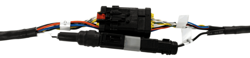
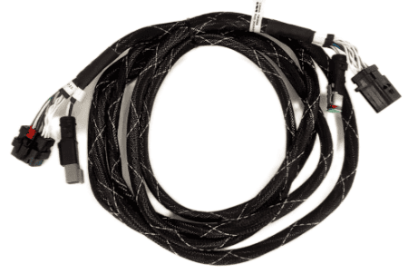
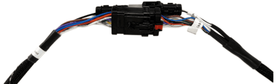
Once the exterior breakout has been connected and routed, connect the T3H-C006 cab breakout harness to the CAB 12-pin AMPSEAL and 2-pin Deutsch DT connectors on the T3H-C002 ECU breakout inside the cab.
An extension should not be needed for the cab breakout harness, and the cab breakout harness should be positioned somewhere out of the way behind covers wherever space is available.
Exterior-Mounted ECU
Avoid routing the cabling into the cab through windows/doors if possible as these may pinch and damage the wires in the harness.
If the COMMAND ECU has been mounted outside the tractor cab, then the cab branch will need to be routed inside of the cab through a hole/cable gland from the rear of the tractor where the ECU is mounted.
Connect the 12-pin and 2-pin connectors on the T3H-C006 cab breakout to the T3H-C002 ECU breakout connectors and route to the cab, extended with T3H-C008 if necessary.
Once the cab breakout has been connected and routed, connect the T3H-C005 exterior breakout to the EXT 12-pin AMPSEAL and 2-pin Deutsch DT connectors at the rear of the tractor.
An extension should not be needed for the exterior breakout harness, and the exterior breakout harness should be positioned somewhere that doesn't block access to other components at the rear of the tractor.