**WARNING:** The **COMMAND** system can automatically control hydraulic movement without operator input. Ensure all personnel remain clear of the implement during operation.
## General Safety Guidelines ##### Read and Understand Instructions Operators must read this manual in full before using the system. Do not operate the system without a complete understanding of its controls and functions. ##### Authorized Personnel Only Only trained and qualified individuals should operate, maintain, or service the **COMMAND** system. ##### Operator Responsibility **COMMAND** is designed to assist with land levelling but does not replace operator supervision. The operator must remain alert and in control at all times. ## Operational Safety ##### Supervise All Automated Movements The landforming implement may move automatically based on GNSS and IMU sensor inputs. ##### Maintain Safe Distance Never stand or allow others to stand near the implement, blade, or hydraulic components while the system is engaged. ##### Manual Override Ensure all operators are familiar with how to disengage or manually override the system in an emergency. ## System Activation Warnings ##### Automatic Movement HazardsThe blade or land levelling implement may move without manual input during automatic operation. Clear the area of personnel before activating the system.
##### Hydraulic Pressure HazardsThis system operates using high-pressure hydraulic components. Do not inspect, service, or disconnect hydraulic lines while the system is active or pressurized. Use caution when working near hoses and actuators.
## Sensor and Signal Dependency ##### GNSS Dependency The system relies on accurate GNSS input. A degraded or lost signal may lead to incorrect implement height or tilt adjustments. ##### IMU Sensor Calibration Incorrect sensor calibration may cause unintended implement movement. ## Terrain and Environmental Awareness ##### Survey Field Conditions **COMMAND** cannot detect soft ground, underground obstacles, ditches, or debris. Make sure to manually inspect and clear the field before using the system. ##### Slope Limits Avoid operating the system on steep or uneven terrain beyond rated slope specifications. Excessive tilt may cause machine tipping or unsafe implement engagement. ## Maintenance Safety ##### Pre-Start Inspection Before each operation, inspect all components, including hydraulic lines, sensor mounts, and electrical connections. ##### Lockout/Tagout for Servicing Fully power down the tractor and disable the land levelling system before performing any maintenance. ## Emergency Protocols ##### Emergency Stop Ensure the operator is aware of the tractor emergency stop mechanism location and function. Test according to machine or implement manufacturer's conditions and recommendations. ##### Error Handling If the system displays a fault code, sensor error, or warning alert, cease operation immediately and refer to Section 10: Troubleshooting. ## Bystander & Site Safety ##### No Passengers Never allow anyone to ride on the implement or tractor while the system is operating. ##### Establish Exclusion Zone Mark the working area clearly. Unauthorized personnel should remain clear of the worksite during automated operations. ## Safety Labelling and Hazard Indicators Ensure all safety labels on the implement and control interface are clean, visible, and intact. Replace damaged or unreadable labels immediately. ## Before Proceeding Before installing or operating the **COMMAND** system: \- Read and understand all safety information in this section \- Ensure all operators are familiar with machine safety and system disengagement procedures \- Contact T3RRA if any information within this manual is unclear **Proceed to Section 2 | System Overview** # 2 | System Overview An overview of the COMMAND hardware and harnessing system # 2.1 | System Architecture ## Theory of Operation **COMMAND** is an electronic control system designed by T3RRA consisting of an Electronic Control Unit (ECU) along with a harnessing system to interface with different sensors, hydraulic and tractor systems. Once installed and configured, the ECU acts as both a control system and interface. It will communicate with a PC running T3RRA software, the earthmoving implement and sensors providing real-time feedback on the position of the implement, and tractor diagnostic data where available. **Level COMMAND** can then control the implement based on your current position and design elevation, while satisfying constraints e.g. cut depth limits. [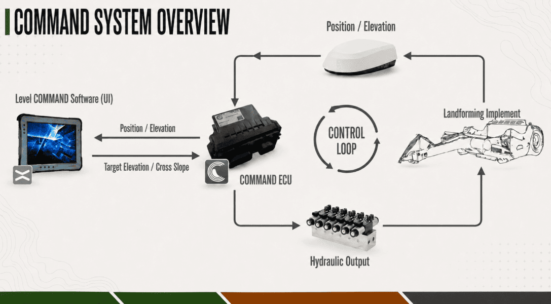](https://docs.t3rra.com/uploads/images/gallery/2026-09/SZtimage.png) ### Manual Control Mode In Manual Control Mode, and also when the system arming switch is deactivated, **COMMAND** is Disengaged and any prescribed elevations sent to the ECU will not result in activation of hydraulics. Hydraulic outputs can still be activated using a connected joystick or tractor SCV levers. These will function regardless of whether **COMMAND** Automatic Control is Disengaged or Engaged. ### Automatic Control Mode Once the operator has Armed the system and Engaged Automatic Control Mode, the ECU activates hydraulic outputs based on: - Prescribed elevation - Current elevation - Calibration parameters - Tracking sensitivity - Tracking/acquire thresholds While Engaged, joystick movement can override automatic control. Depending on configuration, joystick movement can either Disengage Automatic Control Mode or Momentarily Disengage control until the joystick returns to centre. # 2.2 | Supported Implement Types**COMMAND** machine profiles are used to store all configuration settings for that particular implement including GNSS input selections, valve configuration, calibration and tuning values etc.
### Implemented and Tested Machine Profiles **COMMAND** currently has the following machine profiles available for selection on the ECU:| **Machine Profile** | **Controlled Functions** | **Example Usage** |
| Single Scraper - Height | Function 1 - Height | A bucket scraper with single proportional height control valve and a single GNSS receiver |
| Single Scraper - Height & XSlope | Function 1 - Height Function 2 - XSlope / Tilt | A bucket scraper with a single proportional height and single proportional tilt control valve fitted with a single GNSS receiver and single inertial measurement unit (IMU) |
| Single Ditcher - Height | Function 1 - Height | A V-ditcher with a single proportional height control valve and a single GNSS receiver. |
**Machine profiles listed below are currently under development and may become available in future software releases.**
| **Machine Profile** | **Controlled Functions** | **Example Usage** |
| Single Ditcher - Height & Pitch | Function 1 - Height Function 2 - Pitch | A tile plow with a single proportional height, single proportional pitch control valve, single GNSS receiver and single inertial measurement unit (IMU). |
| Tandem Scrapers - Height | Function 1 - Height 1 Function 2 - Height 2 | Two bucket scrapers in tandem, each with a single proportional height control valve and single GNSS receiver. |
| Single Scraper - Dual Height | Function 1 - Height | A bucket scraper with a single proportional height control valve but two GNSS receivers (One on the left of the implement, one on the right) |
| Single Scraper - Height (Dual Cylinder) | Function 1 - Height Left Function 2 - Height Right | A bucket scraper with dual proportional height control valves (controlling left and right height separately), and two GNSS receivers (left and right). Maintains blade angle to allow manual X-Slope / Tilt operation. |
| Single Scraper - Height & XSlope (Dual Cylinder) | Function 1 - Height Left Function 2 - Height Right | A bucket scraper with dual proportional height control valves (controlling left and right height separately), and two GNSS receivers (left and right). |
Receivers being used with **COMMAND** must be capable of RTK positioning calculations.
### NMEA 2000 (CANBUS) [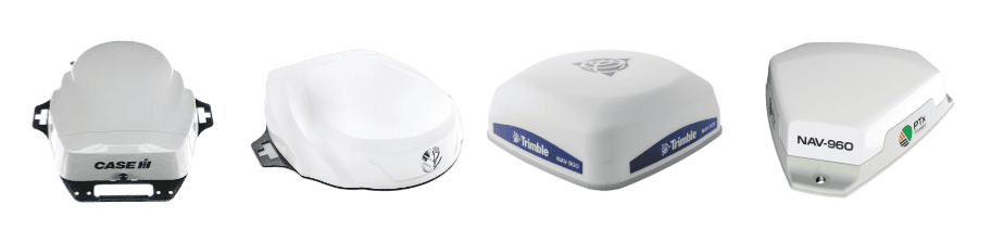](https://docs.t3rra.com/uploads/images/gallery/2026-09/xgyimage.png) **COMMAND** is able to interface with GNSS receivers supporting NMEA 2000 standard output over ISOBUS/CANBUS for position feedback including but not limited to Case Vector Pro, New Holland PLM Cygnus & Trimble NAV 900/960 receivers. #### Supported NMEA 2000 PGNs - **129029** - GNSS Position Data - **129539** - GNSS DOPs - **129025** - Position, Rapid Update - **129026 **- COG & SOG, Rapid Update - **129028** - Altitude Delta, Rapid Update #### Position Update Rate A minimum position update rate of 5 Hz is required. **10 Hz is** recommended. --- ### NMEA 0183 (RS232 Serial) **COMMAND** is able to interface with any receiver capable of providing NMEA 0183 standard sentences over RS232 serial for position feedback. The sentences below are required at a minimum for usage with **Level COMMAND**. [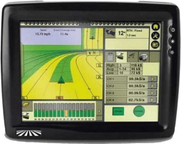](https://docs.t3rra.com/uploads/images/gallery/2025-05/ddgraphic-fm1000.png) #### Required Sentences - **GGA** - Time, position, and fix related data - **GSA** - GNSS DOP and active satellites - **VTG** - Actual track made good and speed over ground #### Optional Sentences - **RMC **- Position, Velocity, and Time - **ZDA **- UTC day, month, and year, and local time zone offset #### Position Update Rate A minimum message rate of 5 Hz is required. **10 Hz is** recommended. #### RS232 Baud Rate The RS232 baud rate can be selected in **Level COMMAND** as 19200, 38400, 57600, and 115200 bps. A baud rate of **38400** is recommended. --- #### **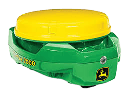** ### John Deere StarFireTM **COMMAND** is able to interface with all modern StarFire receivers over ISOBUS/CANBUS for position feedback, including StarFire 3000, 6000, 7000 & 7500 models.Differential GNSS or SF corrected signals e.g. SF3 are NOT considered suitable for implement position feedback as position accuracy and repeatability are insufficient.
--- ### Compatible Cross-slope / Roll / Tilt Sensors For users making use of Cross-slope control using the **COMMAND** ECU's second output function, we recommend the use of the **T3H-E003** COMMAND Inclination Sensor – TARS-B to ensure that the angle sensor being used is robust and accurate for automatic implement control. #### [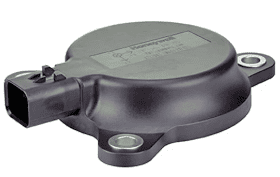](https://docs.t3rra.com/uploads/images/gallery/2025-05/Phaimage.png) #### T3H-E003 - **COMMAND** Inclination Sensor A TARS-B inertial measurement unit configured by T3RRA can be used to provide reliable feedback on the pitch and roll angle of the implement and can be mounted on the scraper for automatic Cross-slope control when using receivers such as Case IH Vector Pro or Trimble NAV 900. #### **** #### StarFireTM TCM (Terrain Compensation Module) **COMMAND** can make use of the in-built StarFire TCM, which provides feedback on pitch and roll angle of the receiver. The StarFire TCM can be selected as a Cross-slope / Tilt sensor but we cannot guarantee the accuracy / bias drift of the sensor and generally recommend the use of **T3H-E003** shown above. # 2.4 | Tractor / Electrohydraulic Compatibility**COMMAND** can make use of either in-built rear tractor electrohydraulic valves, commonly referred to as SCVs (Selectable Control Valves) or auxiliary remotes, or externally mounted electrohydraulic valves.
For each valve type, **COMMAND** is able to provide two raise and lower functions for automatic control of function 1 (e.g. height) and function 2 (e.g. cross-slope / tilt). For CANBUS based valve types, any available SCVs/Remotes will be available for selection. For proportional solenoid, Analog Voltage (0-5V) and Danfoss PVE types, the number of selectable outputs is limited to the number of available physical outputs on the ECU suitable for analog voltage laser inputs or external EH valves.| **Valve Interface** | **Description** | **Applicable Valve Adapter/s** | **Suitable example tractors/valves** |
| *JD CAN* | **COMMAND** can communicate directly with John Deere SCVs over CANBUS, sending flow requests that will be enacted by the John Deere tractor hydraulic system. | N/A | Most modern John Deere tractors, e.g. 8R, 8RT, 9R, 9RT, 9RX. |
| *J1939* | **COMMAND** can communicate directly with the T3RRA VM or other compatible hydraulic controllers using the J1939 messaging standard. | N/A | Challenger tracked machines |
| *Fendt SCR/S4/MT* | **COMMAND** can communicate directly with Fendt SCVs over CANBUS, sending flow requests that will be enacted by the tractor hydraulic system. | Use **T3H-V005** and **S/111** valve adapters. | Fendt SCR, S4 and MT models where the SCV control bus is separated from the ISOBUS. |
| *Fendt ONE* | **COMMAND** can communicate directly with Fendt SCVs over CANBUS, sending flow requests that will be enacted by the tractor hydraulic system. | Use **T3H-V005** valve adapter. | Fendt Gen 7 / ONE tractor models |
| *Analog Voltage (0-5V)* | **COMMAND** can provide 0-5V analog voltage signals suitable for John Deere legacy proportional SCV controller or Case IH / New Holland 0-5V EHR controller inputs. | Use **T3H-V001** valve adapter. | Case 0-5V EHR inputs or John Deere legacy proportional laser inputs. |
| *Proportional Solenoid* | **COMMAND** can provide closed-loop PWM signals suitable for controlling external proportional solenoid valves requiring maximum flow current of less than 2 Amps. | Use **T3H-V002** and **T3H-V003** valve adapters. | Scraper systems using external proportional solenoid valves such as Eaton Vickers, Rexroth or Hydac. |
| *Danfoss PVE* | **COMMAND** can provide 0-Vs ratiometric voltage signals as well as power supply suitable for controlling external Danfoss PVEM, PVEA, PVEH and PVES valves. | Use **T3H-V002** and one of **T3H-V006** or **T3H-V007** valve adapters. | Scraper systems using external closed-loop proportional valves such as Danfoss PVEM, PVEA, PVEH or PVES. |
**Correct component selection is important for reliable installation and operation of the COMMAND system. Harnessing requirements will vary depending on tractor model, implement configuration, GNSS receiver type, and hydraulic interface. For assistance selecting compatible components, use the COMMAND kit picker at t3rra.com or contact T3RRA.**
Factors that will affect harnessing requirements include: - Tractor brand - Tractor model - Scraper brand - Scraper model - GNSS receiver model - Available Electrohydraulic Valves ### Harnessing Compatibility The **COMMAND** harnessing system has been designed to allow us to leverage existing customer and dealer knowledge of tractor and implement harnessing systems. We can then take advantage of this familiarity on the technical support front, while leveraging the fact that dealers also possess many of these parts in stock at-the-ready. #### Typical CNH Components| **SKU / Part No.** | **Name** |
| 115-0172-397 OR 115-0172-398 **OPTIONAL POWER** | Constant Power Harness (Row Crop) OR Constant Power Harness (Articulated) |
| 115-7100-009 OR 115-7100-010 **REQUIRED** | Front Extension Wiring Harness Kit |
| 115-7100-005 **REQUIRED** | Cable Adapter Terminator Gen I ISOBUS |
| 92179218 OR 92317566 **REQUIRED IF NO ISO IBBC PRESENT** | Row Crop Tractor ISO Connector OR Articulated Tractor ISO Connector |
| **SKU / Part No.** | **Name** |
| BPF10403 OR BPF10404 **OPTIONAL** | Constant Power Harness (Row Crop) OR Constant Power Harness (Articulated) |
| BPF11117 **REQUIRED** | Front Extension Wiring Harness Kit (including terminator module) |
| RE174725 OR RE174726 **REQUIRED IF NO ISOBUS PRESENT** | GreenStar™ Ready Field Installation Kit (Rowcrop) OR GreenStar™ ISO Implement Connector Field Installation Kit (Articulated) |
| BPF12658 **REQUIRED IF USING STARFIRE GNSS** | Implement Receiver Wiring Harness Kit |
| BPF10547 **RECOMMENDED** | iGrade Counterbalance Valve kit - highly recommended if the implement has no existing counterbalance mechanism |
The components below are required for a base **COMMAND** installation.
| **SKU / Part No.** | **Name** |
| T3H-E001 | COMMAND ECU – Controller Only |
| T3H-L001 | COMMAND ECU Licence – Licence Only |
| T3H-C002-1 | COMMAND ECU Adapter - CAN & Analog V2 |
| T3H-C003 | COMMAND Arm/Engage Switch Adapter |
| T3H-C004 | COMMAND Arm/Engage Switch |
| T3H-C005 | COMMAND ISOBUS/Ext Breakout Adapter |
| T3H-C006 | COMMAND Cab Breakout Adapter |
| T3H-C008 | COMMAND Cab/Ext Extension Adapter |
| T3H-T001 | Tablet Serial Interface Adapter (RA 4m) |
Components listed below are optional for **COMMAND** and will only be required for certain tractor models, scraper models, GNSS receivers, Tilt sensors or Electrohydraulic valves.
| **SKU / Part No.** | **Name** |
| **Tractor Harnessing** | |
| T3H-F001 | Cab Convenience Power Adapter |
| T3H-F002 | External Loose End Power Adapter |
| T3H-F003 | COMMAND Inline Fuse Adapter |
| T3H-J001 | COMMAND Joystick Adapter – 4m Extension |
| T3H-M001 | COMMAND J1939 Diagnostic Adapter (Green) |
| T3H-T002 | Tablet Serial Interface Adapter (RA 6m) |
| T3H-V001 | COMMAND Legacy Analog Output Adapter |
| T3H-V002 | Valve Adapter – 6m Extension |
| T3H-V003 | Valve Adapter – Prop. Solenoid (2-way DT) |
| T3H-V005 | COMMAND Tractor CAN Valve Adapter |
| **Implement Harnessing** | |
| T3H-E003 | COMMAND Inclination Sensor – TARS-B |
| T3H-G001 | COMMAND NMEA Extension Harness (8m) |
| T3H-G002 | COMMAND Impl Adapter – NAV-900 / Ag372 |
| T3H-G003 | COMMAND Impl Adapter – Emlid Reach RS2/RS2+/RS3 |
| T3H-G004 | COMMAND Trimble NMEA Output Adapter |
| T3H-G007 | COMMAND NMEA Extension Harness (12m) |
| T3H-S001 | COMMAND Impl Adapter – Stub Junction |
| T3H-S003 | COMMAND Impl Adapter - TARS Extension |
All requirements in this section must be confirmed before installing the **COMMAND** system.
Failure to meet these requirements may result in improper operation or system damage.
**Confirm the following before proceeding:** - Tractor compatibility - Power supply suitability - Communication interfaces (ISOBUS or CANBUS, RS232 NMEA 0183) Details for each requirement are provided in the following sections. # 4.2 | Tractor Requirements ## Tractor Requirements **COMMAND's** tractor requirements are as follows: - Provide a suitable power supply as specified in Section 4.3. - Have compatible SCVs or auxiliary control valves - The tractor does not need to be ISOBUS-equipped; however, upgrading to ISOBUS is strongly recommended to provide the necessary connections (e.g. implement breakaway connector). - Be capable of manual implement control. - Be in good working condition with fully functional hydraulics. If any requirement in this section cannot be met, installation should not proceed. ## Implement Compatibility ### Supported Implement Configurations **COMMAND** is currently suitable for use with the following types of implements: - **Implements with a single hydraulic height control function and a single receiver**, i.e. requiring a single valve. This includes implements with multiple height cylinders if the cylinders are linked together and controlled by the same valve. e.g. a basic tractor-pulled bucket scraper. - **Implements with a single hydraulic height control function, single receiver, and a single cross-slope/tilt control function**, i.e. requiring a single separate valve for each (2 total). e.g. JN&R tractor-pulled scraper with cross-slope / tilt cylinder. ### Future Configurations - **Implements with a single hydraulic height control function and dual** **receivers**, i.e. requiring a single valve for height control and a single valve for cross-slope control with both a left and right implement mounted receiver. - **Tandem implements (convoy) each with a single hydraulic height control function**, i.e. one valve controls front scraper height and another valve controls rear scraper height. - **Implements with two separate hydraulic height control functions**, i.e. two separate valves are required to control each side of the implement. e.g. grader-style blades with independent left/right control. - **Two implements towed in tandem with a single height control function each**, i.e. requiring one valve for each implement. e.g. two basic bucket scrapers towed in tandem. ## Implement Definitions The naming conventions below will help to avoid confusion later: **Single implement** - One single blade with one receiver positioned in centre (single-axis or dual-axis) (May or may not be accompanied by IMU). **Tandem implements** - Two blades in front/behind one another as a train, each with a single receiver positioned in the centre (single-axis control only). **Dual receiver** - One single blade with two receivers positioned on the left and right sides of the blade for dual-axis control. The tilting point is assumed to be the centre of the blade edge, in the middle of the two receivers. # 4.3 | Power Requirements A switched 12V DC power supply with a minimum capacity of 10A is required. The harnessing system has been designed to provide flexibility in sourcing 12V DC switched power depending on where the ECU is mounted, and where sources of protected 12V DC power are freely available. The following power supply options are supported: ### Cab Convenience Sockets **COMMAND** can be powered using an available cab convenience power socket along with the T3H-F001 Power Adaptor provided by T3RRA.**NOTE**: A minimum of two cab convenience sockets are required in total if providing power to **COMMAND** and implement harnessing, and a RuggON tablet. Three are required if adding an ISOBUS breakaway connector that requires a convenience power connection e.g. JD ISOBUS plug kit. If fewer than two convenience ports are available, another power option may need to be used for **COMMAND** or the tablet.
**WARNING**: Convenience power supply sockets should be load-dump protected and fused appropriately within tractor electrical systems, and generally are but it's always best to make sure.
| [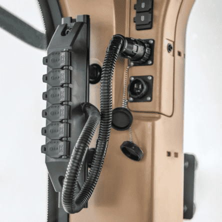](https://docs.t3rra.com/uploads/images/gallery/2025-05/image.png) | [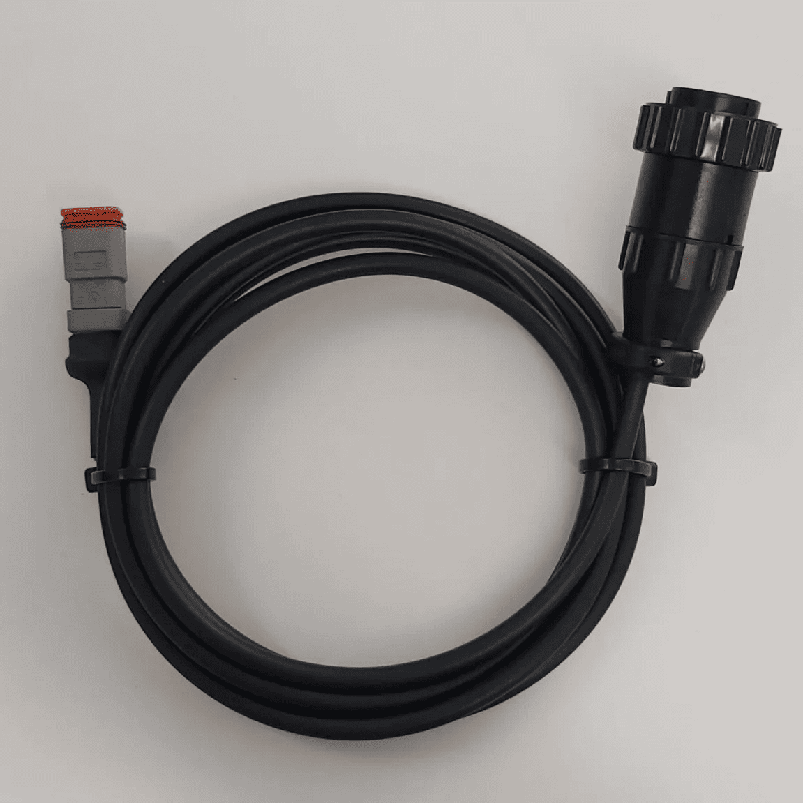](https://docs.t3rra.com/uploads/images/gallery/2025-05/ey8image.png) |
**NOTE:** The Constant Power Harness may not possess its own fusing, but a fuse is supplied on the **T3H-C005** harness to protect against electrical faults.
Connection can also be made directly into the **T3H-C002** EXT branch (Connector C6) if the **T3H-C005** is not required but the aforementioned fuse must still be added for appropriate protection using a **T3H-F003** Inline Fuse Adapter. [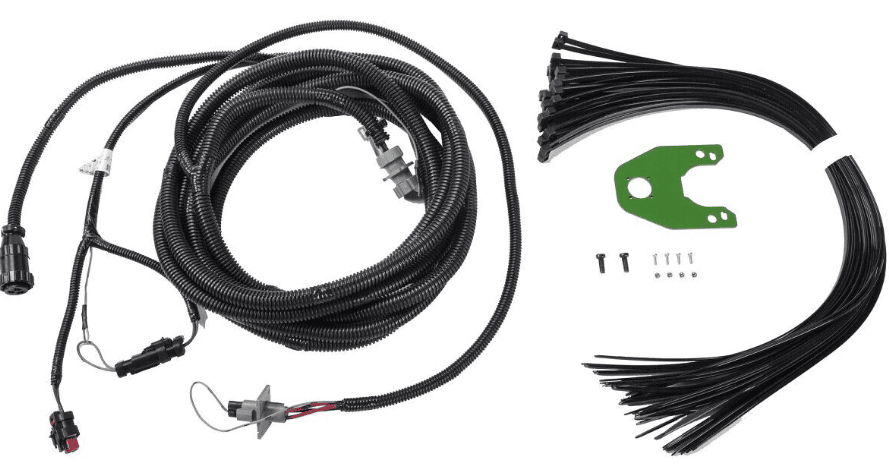](https://docs.t3rra.com/uploads/images/gallery/2025-05/4kHimage.png) ### Providing a Custom Power Connection A custom connection to switched 12V power can be made using the **T3H-F002** Power Adaptor (DT06-2S & Loose Wire Ends). The installing technician must provide the appropriate connections / terminations depending on their own requirements.**NOTE**: Avoid routing power cables near high-current or noisy signals if possible (e.g. alternator).
**WARNING**: The power supply must be rated and protected appropriately for the application!
#### Custom Power Supply Requirements If a custom power source is used, it must meet the following requirements:| **Description** | **Nominal Range / Rating** | **Notes** |
| ***Supply Voltage (V)*** | 9-32V DC | Ripple/noise ≤ 100 mV peak-to-peak recommended; ensure **DC/DC converters** are well-filtered. |
| ***Supply Current (A)*** | 1A for general ECU operation plus 2A per proportional solenoid in use | Depends on connected loads, MCU, sensors, and interfaces. |
| ***Power Supply Protections*** | Overvoltage protection | Must be protected against load dump, inductive spikes, and cranking via TVS diodes or suppression circuits. Transient protection required (TVS diode, suppressor per ISO 7637-2). |
| Overcurrent protection | Must include a fuse or circuit breaker rated to a maximum of 10A. |
**IMPORTANT**: Please ensure you have read the safety information in the previous chapter before commencing installation of **COMMAND**.
### Machine Preparation Complete the following steps before beginning installation of the **COMMAND** ECU:| **Step** | **Check** |
| Move the tractor and implement to a level, hard surface suitable for maintenance work. | |
| Center the steering wheels. For articulated tractors, engage the articulation locks to prevent movement. | |
| Fully lower any attachments or implements to the ground to ensure stability. | |
| Turn off the engine and remove the ignition key. | |
| Block both the front and rear wheels to prevent accidental movement of the machine during installation. | |
| Allow the engine and hydraulic system to cool completely before working near hot components. | |
| Disconnect the battery cables. Place a **“Do Not Operate”** tag in a visible location in the cab, and install a **lockout box** on the battery terminal to prevent accidental power reconnection. | |
| Before opening any hydraulic, pneumatic, or coolant lines, relieve system pressure. Use caution when removing fill caps or hose fittings—cover the area with a clean rag to contain any residual pressure or fluid spray. | |
| Unbox all kit components and verify the contents against the packing list. Lay out the parts on a clean, organized work surface to streamline installation. |
Avoid routing the cabling out of the cab through windows/doors if possible as these may pinch and damage the wires in the harness.
If the **COMMAND** ECU has been mounted inside the tractor cab, then the exterior branch will need to be routed outside of the cab through a hole/cable gland to the rear of the tractor next to the ISOBUS implement breakaway connector. Connect the 12-pin and 2-pin connectors on the **T3H-C005** exterior breakout to the **T3H-C002** ECU breakout connectors, extended with **T3H-C008** if necessary and run the cable out of the cab and to the rear of the tractor. [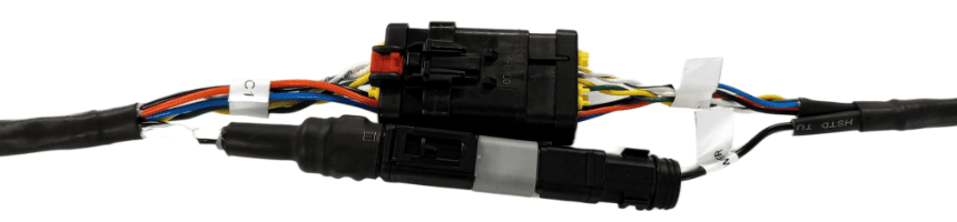](https://docs.t3rra.com/uploads/images/gallery/2025-07/Em25kVgiNjJJ4qRx-image.png) [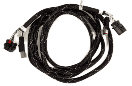](https://docs.t3rra.com/uploads/images/gallery/2025-07/pepXJZOZ84hX8sAW-image.png) Once the exterior breakout has been connected and routed, connect the **T3H-C006** cab breakout harness to the CAB 12-pin AMPSEAL and 2-pin Deutsch DT connectors on the **T3H-C002** ECU breakout inside the cab.An extension should not be needed for the cab breakout harness, and the cab breakout harness should be positioned somewhere out of the way behind covers wherever space is available.
[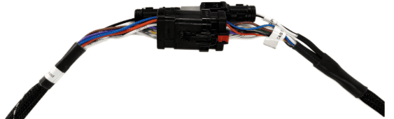](https://docs.t3rra.com/uploads/images/gallery/2025-07/SwPQuG9tPizKIAx6-image.png) #### Exterior-Mounted ECUAvoid routing the cabling into the cab through windows/doors if possible as these may pinch and damage the wires in the harness.
If the **COMMAND** ECU has been mounted outside the tractor cab, then the cab branch will need to be routed inside of the cab through a hole/cable gland from the rear of the tractor where the ECU is mounted. Connect the 12-pin and 2-pin connectors on the **T3H-C006** cab breakout to the **T3H-C002** ECU breakout connectors and route to the cab, extended with **T3H-C008** if necessary. [](https://docs.t3rra.com/uploads/images/gallery/2025-07/SwPQuG9tPizKIAx6-image.png) Once the cab breakout has been connected and routed, connect the **T3H-C005** exterior breakout to the EXT 12-pin AMPSEAL and 2-pin Deutsch DT connectors at the rear of the tractor.An extension should not be needed for the exterior breakout harness, and the exterior breakout harness should be positioned somewhere that doesn't block access to other components at the rear of the tractor.
[](https://docs.t3rra.com/uploads/images/gallery/2025-07/Em25kVgiNjJJ4qRx-image.png) # 5.3 | Powering COMMAND Select the appropriate power supply method based on ECU mounting location. ## Cab-Mounted ECU **COMMAND** can be powered using an available cab convenience power socket along with the **T3H-F001** Power Adaptor provided by T3RRA. When mounted in-cab this is the preferred option. If no convenience power outlets are available, consider using a adapter instead of **T3H-F001** if power strip connections are available.| [](https://docs.t3rra.com/uploads/images/gallery/2025-05/image.png) **Convenience Power and Power Strip Outlets** | [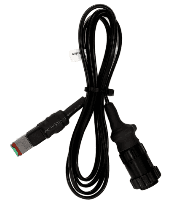](https://docs.t3rra.com/uploads/images/gallery/2025-05/JKGimage.png) **T3H-F001** | [](https://docs.t3rra.com/uploads/images/gallery/2025-07/I5lwggi33GdBQbWW-image.png) **T3H-C002 / T3H-C006** 2-pin Power Input |
Do **NOT** connect unswitched/battery power to **COMMAND's** power input as this will drain battery while the tractor is switched off.
# 5.4 | Connecting COMMAND to the ISOBUS ### ECU Mounted In-cab[](https://docs.t3rra.com/uploads/images/gallery/2025-05/prQimage.png) With the **COMMAND** ECU mounted in-cab: 1. Locate the in-cab 4-way ISOBUS connector. 2. Connect the 4-way ISOBUS connection on the **T3H-C006** cab breakout to the connector. 3. Use an additional adapter if connecting to 9-way cab ISO receptacle. ### ECU Mounted at Rear of Tractor With the **COMMAND** ECU mounted at the rear panel or near the ISOBUS breakaway plug: 1. Disconnect the existing 4-way plug from the ISOBUS implement breakaway connector. 2. Connect the disconnected plug to the receptacle on the ISOBUS "T" connection on the T3H-C005 external breakout. 3. Connect the 4-way ISOBUS "T" plug into the ISOBUS implement breakaway connector. [](https://docs.t3rra.com/uploads/images/gallery/2025-07/ePVWoCuJGpPFqvGH-image.png) # 6 | Cab Hardware Installation This section covers installation of operator interface components and optional control inputs. **Required: - Arm/Engage Switch - Tablet **Optional:** - Joystick - Tractor CAN Connection # 6.1 | Arm/Engage Switch Installation The **COMMAND** Arm/Engage Switch is used by the operator to both Arm/Disarm ECU control outputs, and also to Engage/Disengage automatic control mode. ## Mounting Location ## [](https://docs.t3rra.com/uploads/images/gallery/2026-09/xeHimage.png)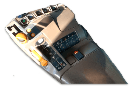 The Arm/Engage Switch should be mounted close to the operator's typical hand resting around the armrest for easy access to Engage or Disengage **COMMAND**'s automatic control mode. Ideally there may be a spare switch position in the armrest as shown below, but if this is not the case then a suitable bracket or enclosure will need to be added to the side of the armrest for example, to provide somewhere for the switch to be mounted. ## Installation Steps ### 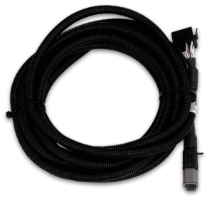 1. Mount the switch near the operator’s armrest for easy access. 2. Install the switch into an available switch cavity or bracket. 3. Connect the **T3H-C003** adapter to the **T3H-C004** switch. 4. Insert the adapter into the mounting location and pull through until the switch is close to the panel. 5. Insert the switch into the mounting location and ensure it is seated correctly. 6. Connect the **T3H-C003** adapter to the **T3H-C006** cab breakout harness. ****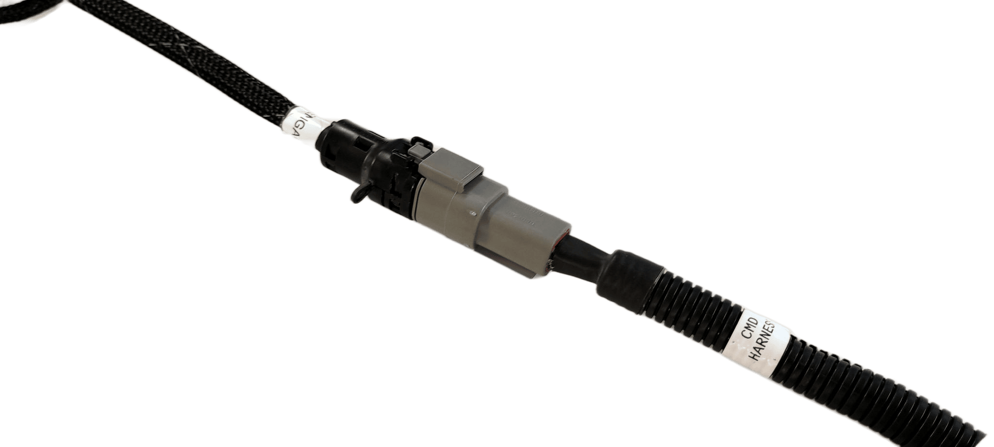**** ## Functionality (Operation) ### [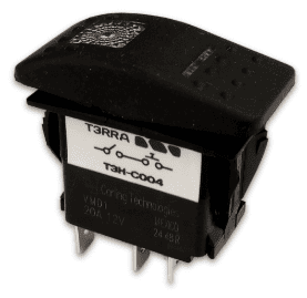](https://docs.t3rra.com/uploads/images/gallery/2025-05/0GTimage.png) The switch has a configuration of OFF-ON-(ON). While in the OFF position, the ECU is disarmed and will not activate outputs or send hydraulic flow commands. The OFF position LED indicates that the ECU is powered. When moved to the middle ON position, **COMMAND** is Armed and prepared for sending output signals or hydraulic flow commands. If using a joystick, **COMMAND** must be armed before the ECU will move the hydraulics. Once in the middle ON position, the operator can then momentarily push into the third (ON) position, which toggles automatic control mode on or off. Please note that automatic control will only Engage once appropriate conditions are met. The idea here, is that once armed the operator may press the momentary button as needed to Engage or Disengage automatic control depending on their requirements.**IMPORTANT**: In the event of an emergency, the operator should switch the Arm/Engage switch to the OFF position to completely disable movement of hydraulics. Please also note that Disarming **COMMAND** will also disable joystick functionality.
# 6.2 | RuggON Tablet InstallationThis section covers installation of a typical RuggON tablet supplied by T3RRA, but these instructions are also relevant to those opting to use their own tablet PC.
## Tablet Mounting Options [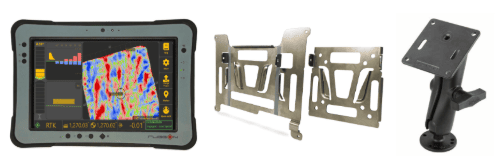](https://docs.t3rra.com/uploads/images/gallery/2026-09/6qQimage.png) The tablet must be mounted somewhere in the cab where the operator can maintain good visibility of the screen.**Ensure the tablet does not obstruct operator visibility while driving.**
Installation of the tablet for **Level COMMAND** is carried out in the same fashion as for any other T3RRA software installation. We highly recommend the RuggON PX501 or SOL7 as a tablet computer solution for use with **Level COMMAND** and provide various accessories for mounting them in the T3RRA Shop. ## Mounting the Tablet 1. Fasten the square silver tablet VESA plate to the square black RAM arm VESA plate. 2. Using a suitable RAM mount or adapter bracket, create a mounting point for the swivelling RAM arm and fasten it to the tractor cab. 3. Position the VESA plate appropriately so that the tablet can be slotted into and removed from the mount easily when required. 4. Fasten the larger silver tablet plate to the back of the PX501 using the provided screws. 5. The tablet is now ready to be slotted into the VESA plate on the black RAM arm and repositioned to the correct viewing angle. 6. The tablet is now ready for connection to **COMMAND**. ## Connecting the Tablet to COMMAND [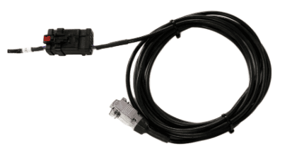](https://docs.t3rra.com/uploads/images/gallery/2025-07/wtZdGGvTz1VKzyxH-image.png) [](https://docs.t3rra.com/uploads/images/gallery/2025-05/cutout-ruggon-rammount.png) 1. Using a **T3H-T001** or **T3H-T002** cable, connect the 12-way AMPSEAL connector to the matching red and black AMPSEAL connector on the T3H-C002 ECU breakout harness. 2. Run the serial cable along the tractor cab wall neatly and fasten to any available points using zip or twist ties. 3. Connect the silver DB9 right angled (RA) or straight connection to the tablet and then secure the connector screws using a small screwdriver. 4. Bundle and tie up any extra length of cable somewhere out of the way. # 6.3 | Joystick Connection (Optional) ## Overview In most cases the manual control of hydraulic functions are already available (e.g. when using existing tractor auxiliary valves). In some limited cases it may be necessary to add operator control for hydraulic functions, e.g. when using an additional valve module, or using direct PWM operation of hydraulic valves from the **COMMAND** ECU. In these situations, two options are available: An analog joystick, or a J1939 CANBUS joystick. If using a compatible analog or J1939 CANBUS joystick, this can be connected to the **T3H-C002** directly or via a joystick extension harness. 1. Ensure the joystick is fitted with an 8-way Deutsch DT plug (DT06-8S). 2. Mount the joystick in an appropriate location in-cab according to manufacturer mounting instructions. 3. Connect the plug to the connector labelled “Joystick” on the **T3H-C002** harness. 4. Verify correct pin alignment before connecting. See below for the pin positions and connector information noting that this is the receptacle on the **T3H-C002** ECU breakout harness. [****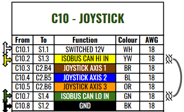****](https://docs.t3rra.com/uploads/images/gallery/2025-07/zWLKzJVazLwvg9sm-image.png) Mating joystick connector parts: - **Connector**: DT06-8S / DT06-8SA - **Contacts**: 1062-16-0122 or AT62-16-0122 ## 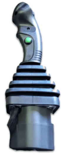Analog Joystick Installation Analog joysticks from brands such as APEM, Parker, Suregrip Controls or Danfoss can be connected to the system and used to manually control one or both available functions, e.g. Height and X-Slope. ### Analog Joystick Specification Requirements - Expected output range: 1.0 - 4.0V - Expected resting voltage: 2.5V ### Analog Joystick Connection The **T3H-C002** ECU Breakout Harness has an 8-pin joystick connection available that can be used to provide switched 12V power and access to the analog joystick signal inputs. Generally, Joystick Axis 1 and Joystick Axis 2 should be connected to the Y and X axis of the joystick respectively. 1\. Connect joystick to the 8-pin joystick connector on the T3H-C002 harness. 2\. Connect power to Switched 12V and GND. 3\. Connect signal outputs to joystick axis inputs. 4\. Verify voltage range is within 1.0–4.0V.**NOTE**: The Joystick Axis 3 signal is currently **not** in use - **COMMAND** is currently capable of controlling 2 functions for manual control.
### Analog Voltage Signal Requirements The joystick output voltage must be centred at 2.5V when not being manipulated, and should lower in voltage to a minimum of 1V in one direction, and to a maximum of 4V when moved in the opposite direction.**IMPORTANT**: 0-5V Output range joysticks cannot be used with **COMMAND**, as input voltages of 0V and 5V are assumed to be a short circuit to ground or 5V respectively.
## J1939 / CANBUS Joystick Installation ### [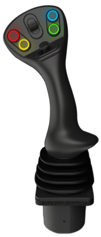](https://docs.t3rra.com/uploads/images/gallery/2025-05/8b5image.png) A ruggedised multifunction J1939 CANBUS joystick with suitable output messages can be connected to the joystick connection on **COMMAND** harnessing to provide manual operator control of the scraper. A J1939 joystick such as the APEM HF Series J1939 joysticks can be connected to the system and used to manually control the two available functions, e.g. Height and X-Slope. ### Interface Parameters - Baud rate: 250 kbps - Transmission repetition rate: Recommended 10 hz or higher ### Connection The joystick connector on **COMMAND** harnessing can provide a 12V DC supply for the joystick, and then receive joystick position messages back via CANBUS. The **COMMAND** ECU has been programmed with J1939/ISO basic joystick message types to provide selection between fore/aft, left/right and twist axes for each of **COMMAND's** control functions. See below for pinout information. 1\. Connect joystick power to Switched 12V and GND. 2\. Connect CAN HI and CAN LO to ISOBUS HI and LO. 3\. Verify communication at 250 kbps. 4\. Confirm joystick inputs are detected in **Level COMMAND**. ### Expected Message Protocol **Message 1 - BJM1 - PGN 0xFDD6** Primary X-axis or Y-axis can be assigned to **COMMAND** function 1 or function 2. [](https://docs.t3rra.com/uploads/images/gallery/2025-06/BNiW33vygTUywzm2-image.png) **Message 2 - EJM1 - PGN 0xFDD7** Primary Z-axis or Y-axis can be assigned to **COMMAND** function 1 or function 2. [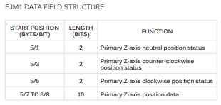](https://docs.t3rra.com/uploads/images/gallery/2025-06/Pa4eluYZ0UaFrnK9-image.png)For more assistance in setting the selected joystick type and joystick axes within **Level COMMAND**, please refer to the **Level COMMAND** manual.
# 6.4 | Tractor CAN Connection (Optional) ## Overview **COMMAND** can be connected to a 250 or 500kbps Tractor CANBUS if present, allowing the ECU to read tractor data directly from tractor systems including parameters such as engine load, hydraulic oil temperature, wheel speed and instantaneous fuel usage. This data can then be displayed in the widgets in **Level COMMAND** in real-time, and is also used in the background for certain control features.Connecting to an incorrect CANBUS, or having **COMMAND**'s Tractor CAN port set to the incorrect baud rate may cause tractor system errors.
## Required PartsA port replicator is included on the **T3H-M001** adapter so that other devices may be connected to the diagnostic connector when necessary without removal of **COMMAND** harnessing.
If the tractor has a Type I diagnostic connection, **T3H-X004** should be added to maintain the Type I connection for the tractor.
#### Type I J1939 Diagnostic Connection (Black) - **T3H-M001 -** COMMAND J1939 Diagnostic Adapter (Green) - **T3H-X004** - J1939 Type I-Type II diagnostic adapter #### [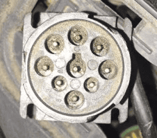](https://docs.t3rra.com/uploads/images/gallery/2025-07/Eeaqyn5Qyoq9Wnxp-image.png) #### Type II J1939 Diagnostic Connection (Green) - **T3H-M001 -** COMMAND J1939 Diagnostic Adapter (Green) #### [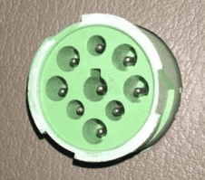](https://docs.t3rra.com/uploads/images/gallery/2025-07/fqsiIdH5VMh2NjBG-image.png) ## Connection Process 1. Connect the **T3H-M001** adapter to the appropriate diagnostic plug in the cab of the tractor. 2. Connect the **T3H-M001** adapter to the **T3H-C006** Cab Breakout Adapter. 3. If appropriate tractor data is present on the tractor bus, **COMMAND** will begin reading the data and providing it to **Level COMMAND** software. 4. Check whether any new widgets have appeared with new data in the Widgets menu of **Level** **COMMAND**. [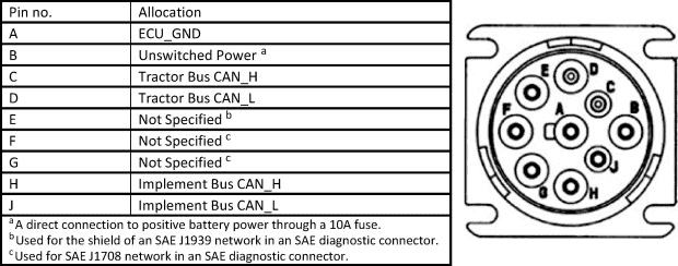](https://docs.t3rra.com/uploads/images/gallery/2025-07/sLA6D5PncKZ4YrIr-image.png) # 7 | Tractor / External Valve Connection & Setup **COMMAND** can interface with tractor hydraulic systems using different connection methods depending on tractor type and model. Determine the correct connection method before proceeding: \- John Deere CAN (Modern tractors with ISOBUS control) \- John Deere Legacy (Analog SCV control systems) \- CNH AFS Connect / PLM Intelligence (Modern systems) \- CNH Pre AFS Connect / PLM Intelligence (Legacy systems) \- Supported Versatile L4WD and DeltaTrack tractors \- Fendt 800 SCR/S4 (CAN valve control via S/109 adapter) \- Fendt 900 SCR/S4 (CAN valve control via S/111 adapter) \- Fendt / Challenger MT (CAN valve control via S/082 adapter) # 7.1 | Modern John Deere (CANBUS) **Applicable to:** John Deere tractors with CANBUS-based SCV control (typically 2005+ models). [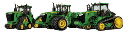](https://docs.t3rra.com/uploads/images/gallery/2025-07/pxNGFIP4M5lnhasT-image.png) ## Connection Method John Deere CANBUS-based SCV systems are controlled by **COMMAND** directly over the ISOBUS, so the only hardware requirement for direct control is that COMMAND be connected to the tractor ISOBUS via the 4-way Deutsch DT connections on either the cab (**T3H-C006**) or external (**T3H-C005**) breakout harnesses. ## Installation Steps 1\. Connect **COMMAND** to the ISOBUS using either: \- **T3H-C006** (in-cab), or \- **T3H-C005** (rear ISOBUS) 2\. Ensure a secure connection at the 4-way Deutsch connector. 3\. Power on the system and verify ISOBUS communication. (See Section 5.4) ## Operation Notes **COMMAND** interfaces with modern John Deere tractors by sending CANBUS messages to the integrated valve controller, commanding either port A or port B flow of the rear tractor SCVs. To operate the SCVs in automatic control mode, the user must push the respective SCV lever into the detent position (not float). This will cause "AUTO" to appear on the console/display to indicate that the SCV is ready for automatic control commands. Moving the lever will disengage AUTO mode on the console/armrest but "AUTO" may remain visible in the SCV status area as it's still in automatic control mode. To re-enter AUTO mode, push the SCV lever into detent position again.**IMPORTANT**: Moving the SCV lever will disengage AUTO mode in modern JD tractors, so movements based on any current valve signals will cease. Always keep this in mind during operation - the lever must be pushed into detent position again to resume automatic control.
For more information on configuring **COMMAND** for use with John Deere CAN SCVs, refer to the **Level COMMAND** Manual.
# 7.2 | John Deere Legacy (Analog) **Applicable to:** John Deere tractors with analog SCV control (typically pre-2005 models). [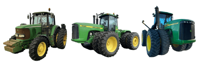](https://docs.t3rra.com/uploads/images/gallery/2025-07/2RFwr0u047bF0F0B-image.png) ## Connection Method **COMMAND** can control John Deere legacy valve systems through the use of a **T3H-V001** **COMMAND** Legacy Output Adapter. ## Installation Steps #### 10-way Metripack 150 Series Connection 1. Connect the **T3H-V001** adapter to the **T3H-C002** ECU breakout harness at the round Deutsch HD series connector. #### [](https://docs.t3rra.com/uploads/images/gallery/2025-07/CWrcAdy0xnqMfSop-image.png) 2\. Connect the 10-way Metripack connector on **T3H-V001** to the tractor's SCV signal input plug. ## John Deere SCV Controller Connection Overview [](https://docs.t3rra.com/uploads/images/gallery/2025-06/S1UiDBeLj4L7cY1d-image.png) [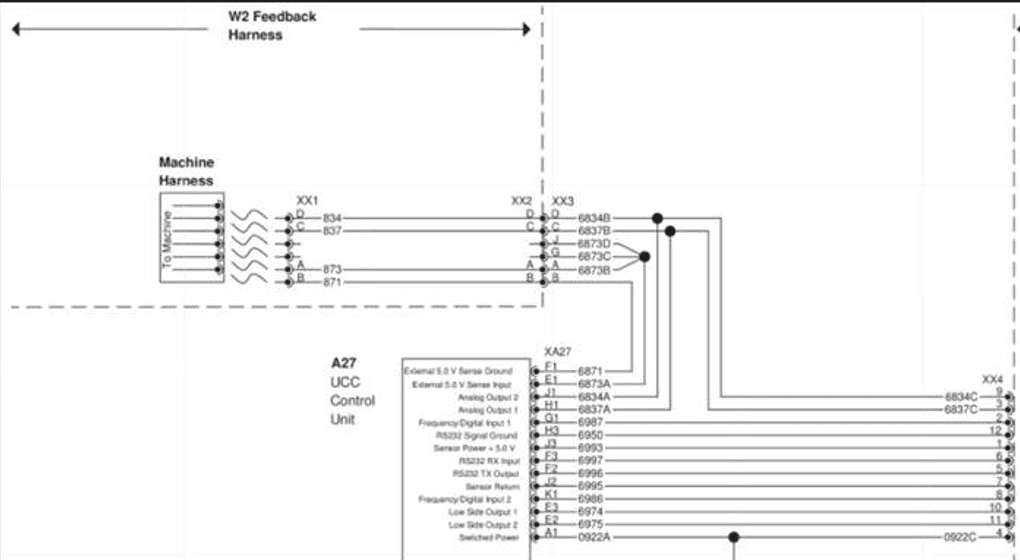](https://docs.t3rra.com/uploads/images/gallery/2025-06/v9gdrQPYeMUY0uyl-image.png) ## Operation Notes **COMMAND** interfaces with legacy John Deere tractor SCVs by sending analog voltage signals to the integrated valve controller, commanding either port A or port B flow of two of the rear tractor SCVs (generally SCV1 and SCV3). To operate the SCVs in automatic control mode, the user must push the respective SCV lever forward into the detent position. This will cause "AUTO" to appear on the console/display to indicate that the SCV is ready for automatic control commands. Moving the lever will disengage AUTO mode on the console/armrest. To re-enter AUTO mode, push the SCV lever into detent position again.**IMPORTANT**: Moving the SCV lever will disengage AUTO mode in modern JD tractors, so movements based on any current valve signals will cease. Always keep this in mind during operation - the lever must be pushed into detent position again to resume automatic control.
For more information on configuring **COMMAND** for use with JD Legacy Proportional SCVs, refer to the **Level COMMAND** Manual.
# 7.3 | CNH Direct Connect (AFS Connect / PLM Intelligence) **Applicable to:** Case IH / New Holland tractors with AFS Connect or PLM Intelligence systems. [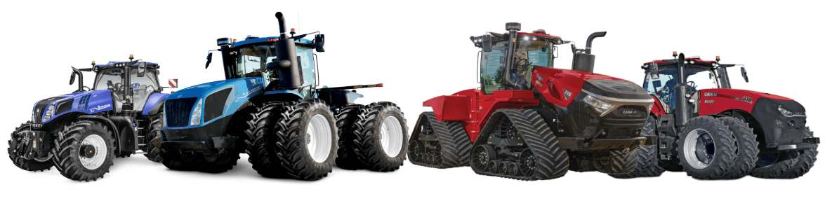](https://docs.t3rra.com/uploads/images/gallery/2025-07/HBhMQQ3eVQl7QHWG-image.png) ## Connection Method **[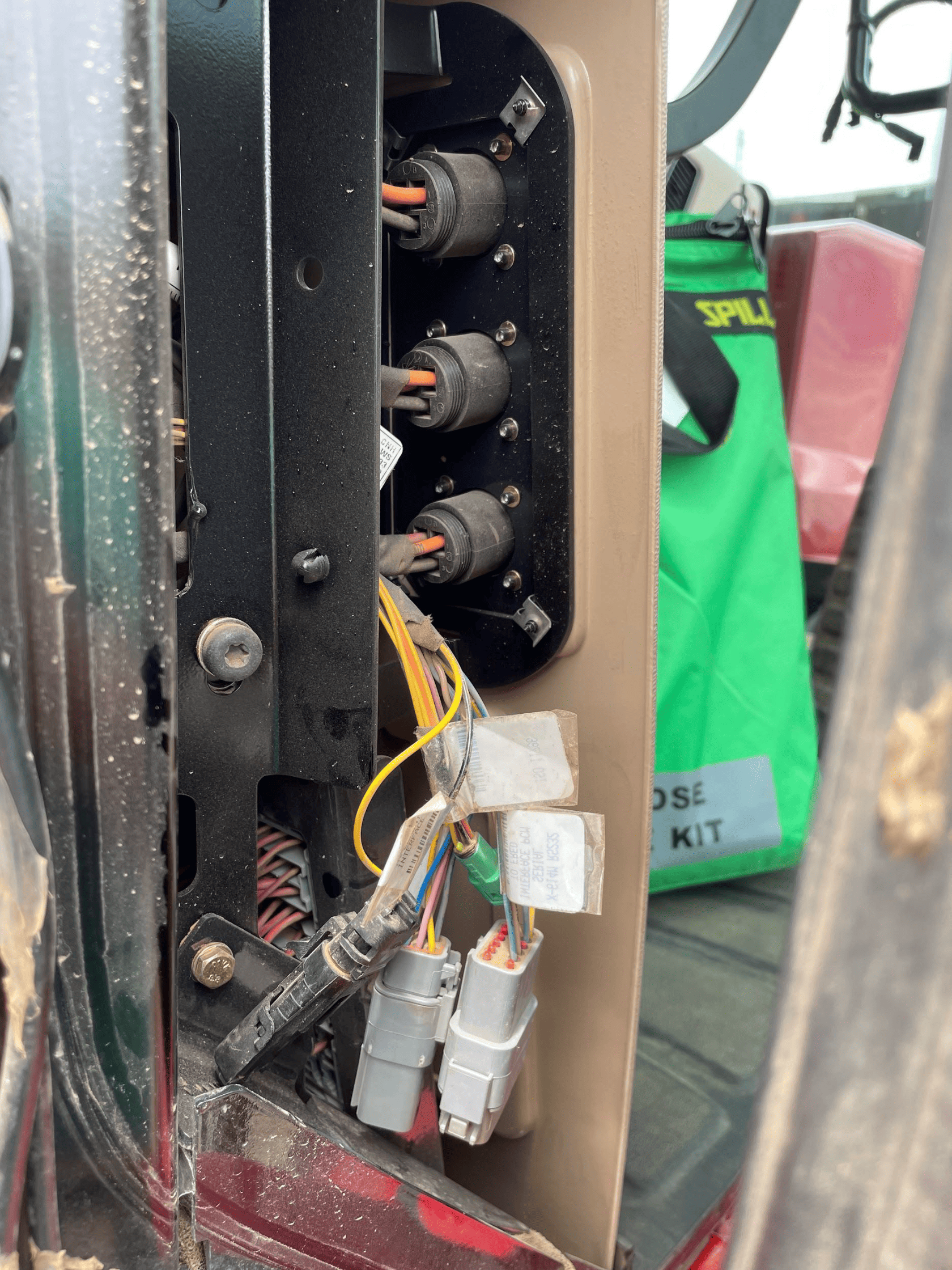](https://docs.t3rra.com/uploads/images/gallery/2025-06/R3uuiKBzm8bcb1Oq-image.png)COMMAND** can control Case & New Holland rear tractor valve (EHR) systems through the use of a **T3H-V001** **COMMAND** Legacy Output Adapter. ## Installation Steps The Case / New Holland tractor connection for analog control signal inputs via the **T3H-V001** adapter are generally found in one of three locations depending on tractor model: 1\. Locate the tractor SCV signal input connector: \- Fuse compartment \- Behind driver seat \- Under cab exterior (4WD models) 2\. Connect the **T3H-V001** adapter to the tractor connection. 3\. Connect the **T3H-V001** adapter to the **T3H-C002** harness. [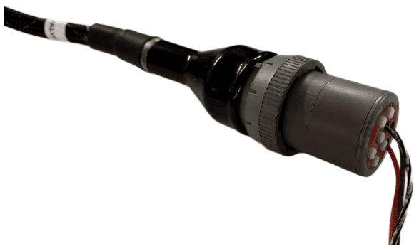](https://docs.t3rra.com/uploads/images/gallery/2025-07/ywPFWUQXnCahBXUF-image.png) ## Tractor Valve Configuration 1\. After completing the physical connection, the system must be configured on the tractor armrest display. [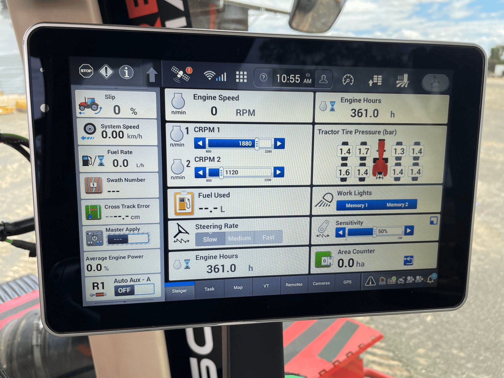](https://docs.t3rra.com/uploads/images/gallery/2025-06/6citV3azhXn8CjJm-image.png) 2\. Ensure that a new implement profile has been created for use with the scraper, or that the currently selected profile is appropriate. [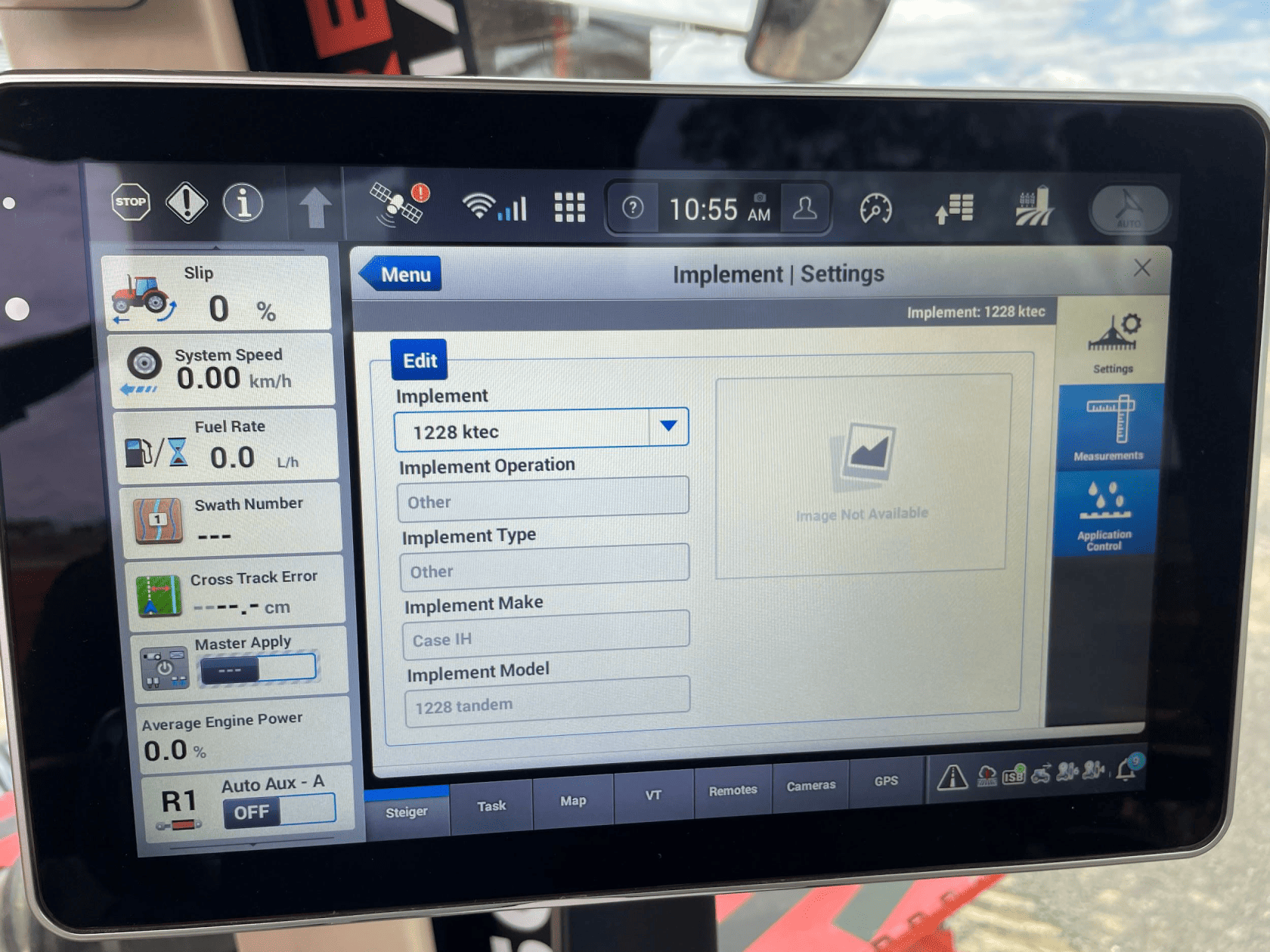](https://docs.t3rra.com/uploads/images/gallery/2025-06/KB1fxjEPXkB2epeJ-image.png) 3\. Open the “Remotes” settings tab to display remote valve configuration. [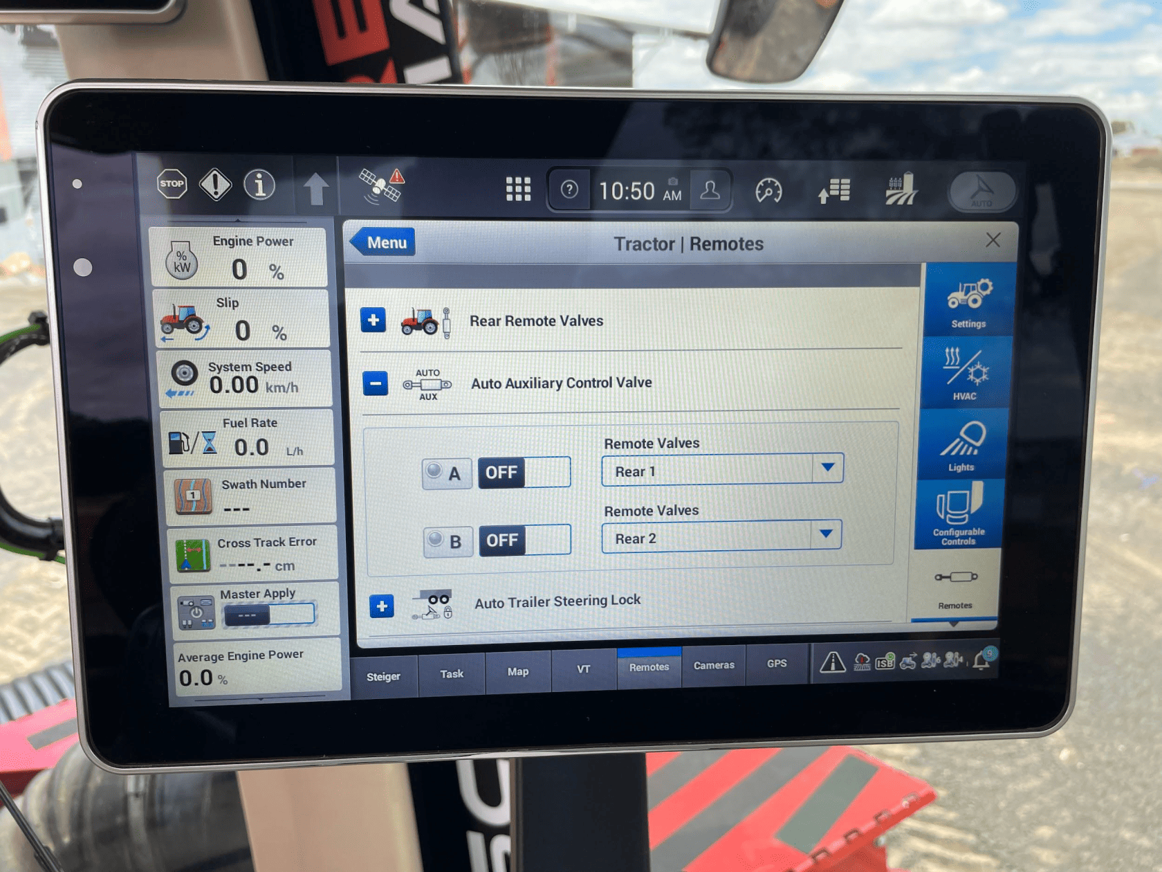](https://docs.t3rra.com/uploads/images/gallery/2025-06/4H2xNOyVIHbWMUJF-image.png) 4\. Set the desired remote valve outputs at the back of the tractor to the desired function (A or B). [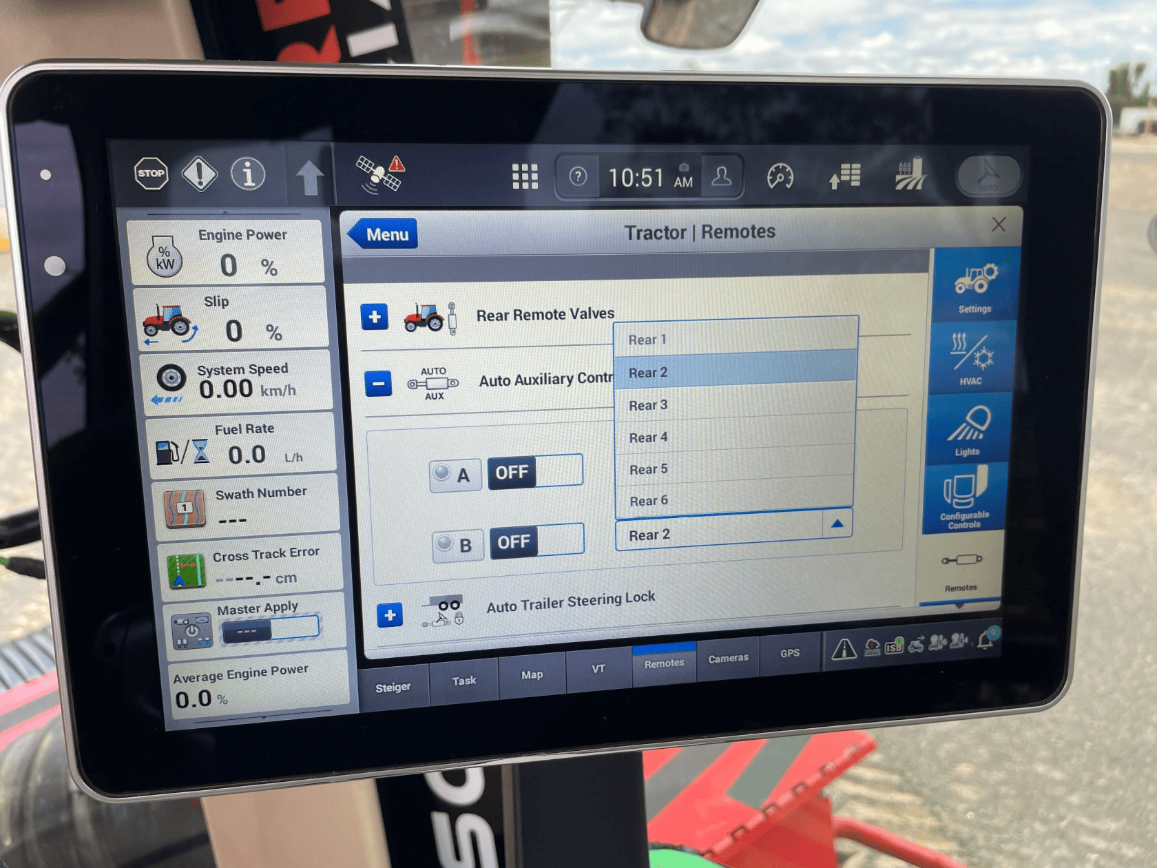](https://docs.t3rra.com/uploads/images/gallery/2025-06/m6PNSJkMFxWwK435-image.png) **NOTE**: The remote valves selected for A and B should be matched to the valve connections at the back of the tractor pictured below. We recommend setting auxiliary valve A to remote valve “Rear 1”, and setting auxiliary valve B to remote valve “Rear 2”, which will configure remote valves 1 and 2 at the back of the tractor for use with **COMMAND**. [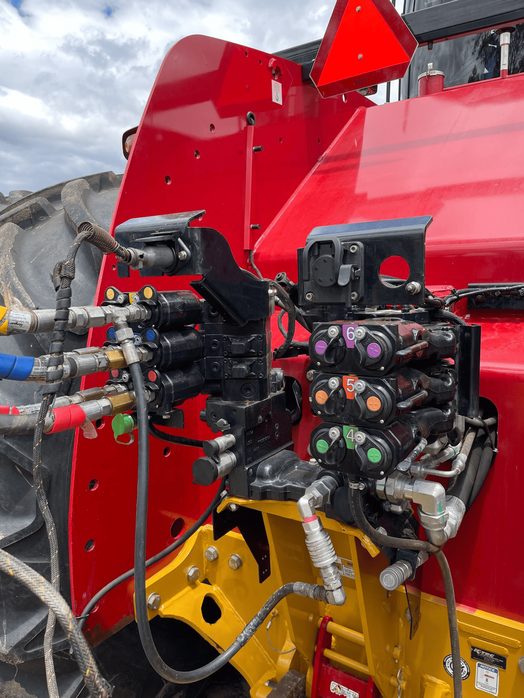](https://docs.t3rra.com/uploads/images/gallery/2025-06/uy2QGbE152OG4u48-image.png) 5\. Once the remote valves on the tractor have been set to the desired auxiliary function, the machine should now be fully configured and ready for use. In order to engage auxiliary control, the user must ensure that the Auto Auxiliary Control Valves A & B have been turned on in the relevant area on the “Remotes” page. 6\. The “Auto Auxiliary Control Valve” can be accessed either by the hydraulic cylinder shortcut next to the display navigation dial on the armrest, or by adding the menu to the display home page. Once this menu is accessed, turn either or both required function to the on position and briefly push the selected remote valve lever forward until it clicks, then release it. The lever returns to its resting position. [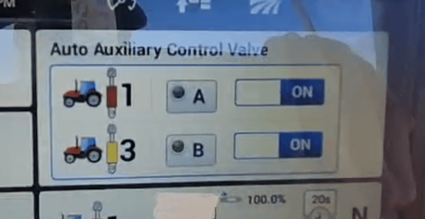](https://docs.t3rra.com/uploads/images/gallery/2025-06/IpXIImajv9x3G1CJ-image.png) ## Operation Notes **COMMAND** interfaces with the Case / New Holland tractor valves by sending analog signals to the integrated valve controller, commanding either port A or port B flow of two of the rear tractor SCVs (For AFS Connect models any SCV can be linked to either of the two analog inputs). To operate the SCVs in automatic control mode, the user first needs to arm one or both of the configured auto SCVs by toggling the Auto Auxiliary Control Valve toggles to ON. Then, either push the respective SCV lever forward into the detent position or press the respective SCV button in front of the levers. This will cause the A and/or B LEDs on the pro 1200 screen to change to solid green, indicating the valves are active for automatic control. Levers can be moved manually, which will override automatic control and once let go, automatic control will resume. To disable automatic control, pull or push the respective SCV lever until it clicks. The A or B LED on the pro 1200 screen should now begin flashing, meaning that automatic control is paused until the operator resumes by pushing the lever to detent or pressing the SCV button again.**IMPORTANT**: Moving the SCV lever alone will NOT disengage AUTO mode in modern case tractors, so movements based on any current valve signals will continue. Always keep this in mind during operation.
For more information on configuring **COMMAND** for use with Case / New Holland auxiliary rear valve control inputs, please refer to the **Level COMMAND** Manual.
# 7.4 | CNH Pre AFS Connect / PLM Intelligence **Applicable to:** Case IH / New Holland tractors prior to AFS Connect or PLM Intelligence systems. [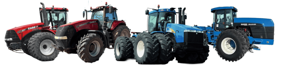](https://docs.t3rra.com/uploads/images/gallery/2025-07/3zce9clzBH4n9Ehs-image.png) ## Connection Method **[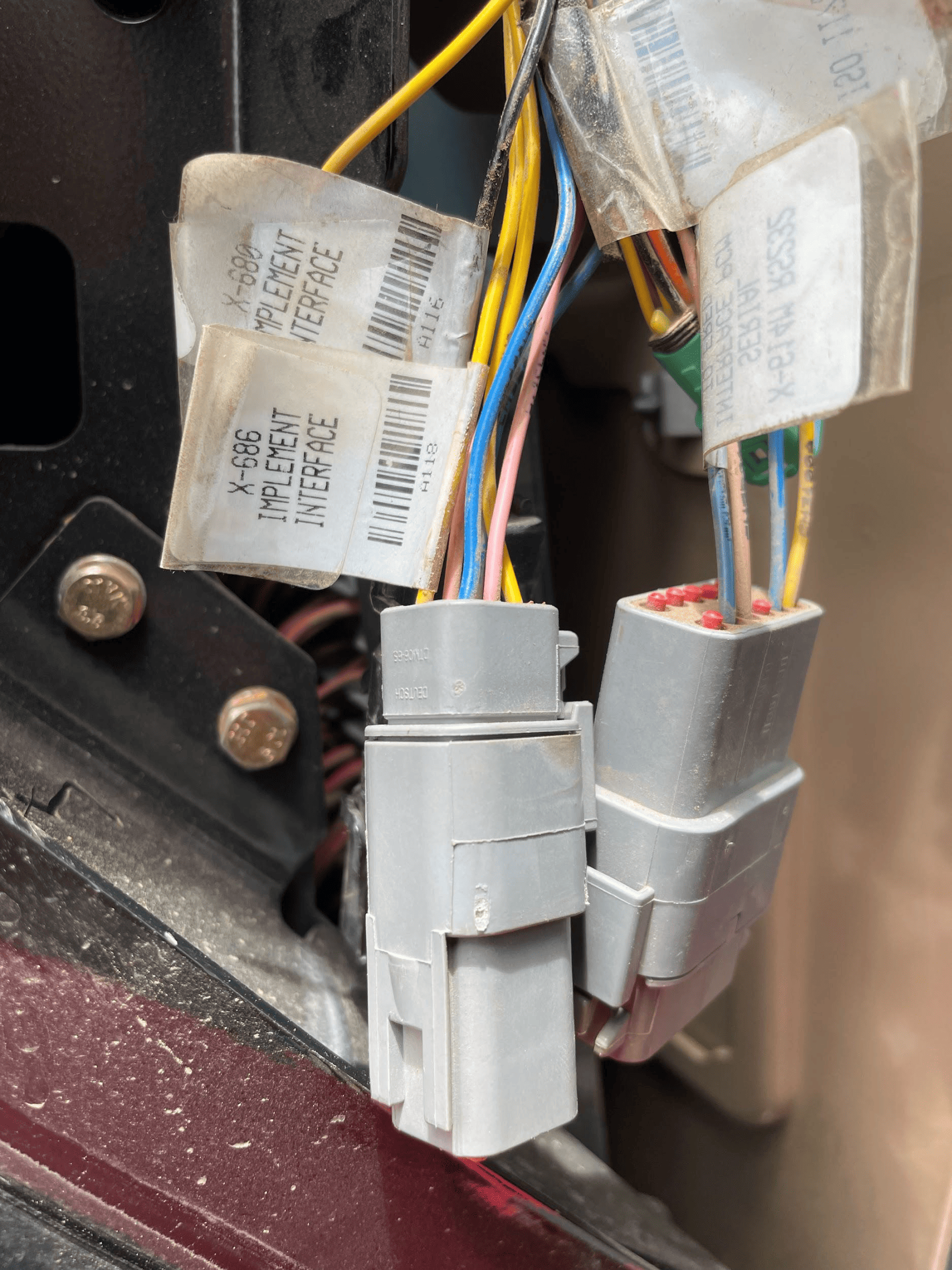](https://docs.t3rra.com/uploads/images/gallery/2025-06/UXcDtoEbWqZOG4bC-image.png)COMMAND** can control Case analog input (EHR) valve systems through the use of a **T3H-V001** COMMAND Legacy Output Adapter. ## Installation Steps The Case / New Holland tractor connection for analog control signal inputs via the **T3H-V001** adapter are generally found in one of three locations depending on tractor mode: 1\. Locate the tractor SCV signal input connector: \- Fuse compartment \- Behind driver seat \- Under cab exterior (4WD models) 2\. Connect the **T3H-V001** adapter to the tractor connection. 3\. Connect the **T3H-V001** adapter to the **T3H-C002** harness. [](https://docs.t3rra.com/uploads/images/gallery/2025-07/ywPFWUQXnCahBXUF-image.png) ## Tractor Valve Configuration Select the applicable configuration method: \- New-style instrument cluster \- Old-style instrument cluster \- Tier IV systems ### New-style Instrument Cluster #### Entering The Configuration Menu - Locate the corner post instrument cluster in the tractor cab (Pictured right). - Power up the tractor and press the PROG button on the instrument cluster until “CONFIG MENU” appears. - Press the “DECR” button until AUX/Hitch/PTO is highlighted and then press the “PROG” button. - Navigate to “EHR MENU” using the up and down arrow buttons and press the “PROG” button. #### Setting Auxiliary Mode - Use the Up/Down arrow buttons to find “AUX VIEW” and then press the “PROG” button. - Use the Up/Down arrow buttons until “SCRPR OPTION” appears and then press the “PROG” button. - Depending on the implement being used, select the correct option using the Up/Down arrow buttons and then press the “PROG” button. - For single implement height control only - “1 LASER” - For dual implement height control - “2 LASER” - For single implement height & cross-slope control - “2 LASER” #### Exiting The Configuration Menu - Press the Up/Down arrow buttons until “AUX EXIT” is shown and then press the “PROG” button. - Press the Up/Down arrow buttons until “EXIT TMF MENU” is shown and then press the “PROG” button. - Press the Up/Down arrow buttons until “EXIT” is shown and then press the “PROG” button. #### Auto/Manual System Operation - The tractor will require an Auxiliary (1-3) switch, which is used to toggle between automatic and manual operation for the two auxiliary inputs. - To toggle between Automatic and Manual operation for either SCV1 or SCV3, press the relevant side of the auxiliary (1-3) switch. [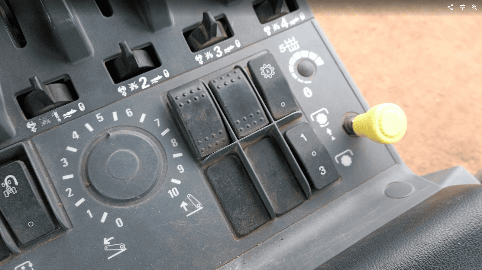](https://docs.t3rra.com/uploads/images/gallery/2025-07/dJF8eLdCINg0NC7q-image.png) ### Old-style Instrument Cluster #### Enabling Auxiliary/Remote Valve Control - Turn on the tractor key switch and within 10 seconds, press and hold the “PROG” button on the instrument cluster for 3 seconds - “INST SET MENU” should appear. - Press the “INCR” or “DECR” buttons until “AUX SET MENU” is displayed, then press the “PROG” button. - Press the “INCR” or “DECR” buttons until “AUX SETUP” is displayed, then press the “PROG” button. - Press the “INCR” or “DECR” buttons to set the required number of “scrapers” between NONE, 1 and 2. In this situation a “scraper” can be considered equivalent to an SCV. - For single implement height control - select 1 SCRAPER - For dual implement height control - select 2 SCRAPER - For single implement height & cross-slope control - select 2 SCRAPER - Press the “PROG” button to accept the number of scrapers on the display. #### Exiting The Configuration Menu - Press the “INCR” or “DECR” buttons until “AUX EXIT” is displayed, then press the “PROG” button. - Press the “INCR” or “DECR” buttons until “EXIT SET MENU” is displayed, then press the “PROG” button. - To complete the calibration process, use the key to turn the ignition off. ### CNH Tier IV #### Enabling Auxiliary/Remote Valve Control - Turn on the tractor ignition key switch and within 10 seconds, press and hold the “ENTER” button on the keypad to enter the Config Menu. - Press the Up or Down arrow keys until “TCU” is displayed and then press “ENTER”. - Press the Up or Down arrow keys until “EHR MENU” appears and then press “ENTER”. - Press the Up or Down arrow keys until “EHR SETUP” is displayed and then press “ENTER”. - “SCRPR NONE” will likely be displayed on the screen. Press the Up or Down arrow button until either “SCRPR 1 LASER” or “SCRPR 2 LASER” is displayed depending on the user’s application and then press “ENTER”. - For single implement height control only - select 1 LASER - For dual implement height control - select 2 LASER - For single implement height & cross-slope control - select 2 LASER - The user can now navigate out of the setup screens or turn the key off - the selected setting will be saved. #### Auto-Auxiliary Mode Operation - The user can toggle between Automatic and Manual operation of the auxiliary outputs using the “1” and “3” buttons on the console. - The LED on the relevant button will be illuminated when in Automatic operation mode. - During operation in automatic mode, the upper portion of the programmable display will show the auto state of the auxiliary outputs. - Automatic control can be temporarily overridden by the operator using the remote hydraulic lever, which will cause the indicator LED on the “1” or “3” console button to flash. ## Operation Notes **COMMAND** interfaces with the CNH external remotes/valves by sending analog signals to the integrated valve controller, commanding either port A or port B flow of two of the rear tractor SCVs (For AFS Connect models any SCV can be linked to either of the two inputs, whereas older models are limited to SCV1 and SCV3). To operate the SCVs in automatic control mode, the user first needs to arm one or both of the configured auto SCVs using the 1/3 switch, display or buttons on the armrest .**IMPORTANT**: Moving the SCV lever alone will NOT disengage AUTO mode in modern case tractors, so movements based on any current valve signals will continue. Always keep this in mind during operation.
For more information on configuring **COMMAND** for use with Pre AFS Connect / PLM Intelligence SCVs, refer to the **Level COMMAND** Manual.
# 7.5 | Versatile — Analog Scraper Control **Applicable to:** Supported Versatile L4WD and DeltaTrack tractors fitted with the 6-pin **C920** laser/scraper control interface connected to the tractor Gateway Control Module (GCM).**NOTE:** MFWD models may use a different interface arrangement. The 400 HP R3T3 MFWD documentation specifies separate installation instructions; the connection and setup procedure below has not been verified for that arrangement.
[](https://docs.t3rra.com/uploads/images/gallery/2026-09/Dhkimage.png) ## Connection Method **COMMAND** controls the tractor’s rear electrohydraulic remote valves through the **T3H-V001** analog output adapter and the tractor’s 6-pin scraper interface connection. The tractor interface provides control of two remote valves: - **Input 1:** Remote valve 1 - **Input 2:** Remote valve 3 ## Installation Steps 1\. Complete the machine preparation steps in Section 5.1 and isolate the tractor electrical supply. 2\. Remove the electrical compartment cover at the rear of the cab, behind the operator’s seat. 3\. Locate the 6-pin scraper interface connector near the Gateway Control Module. In the Versatile installation documentation, this connector is identified as **C920**. [](https://docs.t3rra.com/uploads/images/gallery/2026-09/GAGimage.png) 4\. Connect the tractor-side 6-pin connection of the **T3H-V001** adapter arrangement to the scraper interface. 5\. Connect the **T3H-V001** adapter to the valve output connection on the **T3H-C002** ECU breakout harness. [](https://docs.t3rra.com/uploads/images/gallery/2026-09/PmSimage.png) 6\. Secure the harness clear of moving parts and sharp edges, refit the compartment cover and restore the electrical supply.**NOTE:** If the scraper interface is not fitted, the appropriate tractor interface harness must be installed first. Versatile specifies interface kit **86053584** for the models covered by installation instructions **89004246**. The documented 400 HP R3T3 MFWD arrangement uses kit **86094592**, with installation instructions **89007622**. Have the Versatile dealer confirm the correct kit for the tractor model and serial number and follow the corresponding installation instructions.
## Tractor Valve Configuration The tractor’s scraper control interface is disabled by default and must be enabled through the Electronic Instrument Cluster. 1\. Keep **COMMAND** disarmed and turn on the tractor ignition. 2\. Use the display **Up/Down** buttons to navigate to **CALIBRATION**. 3\. Press **OK (SELECT)** until **Scraper Control** is displayed. [](https://docs.t3rra.com/uploads/images/gallery/2026-09/gxMimage.png) 4\. Press **Show subscreen**. 5\. Press **OK** to change the setting from **OFF** to **ON**. [](https://docs.t3rra.com/uploads/images/gallery/2026-09/Xncimage.png) 6\. Press **EXIT** to complete the setup. 7\. On the EHR monitor, select **Manual Operation** for remote valves **1 and 3**, and leave both hydraulic control levers in **neutral**.**IMPORTANT:** Do not select **Continuous** mode for remote valves 1 and 3 when using the scraper control interface.
**NOTE:** Compatible tractor software is required. Versatile instructions **89004246** specify gateway software **D2T411 or later** for the covered Tier 4i models, **D2T311 or later** for the covered Tier 3 models, and dash software **EICD214**. Software requirements for other models must be confirmed with the Versatile dealer. If the **Scraper Control** option is unavailable, have the dealer verify the tractor’s software and interface configuration.
[](https://docs.t3rra.com/uploads/images/gallery/2026-09/vnaimage.png) ## Operation Notes Once Scraper Control is enabled and the remotes are configured as above, the tractor accepts external control signals while the remote levers are in neutral. No lever detent action is required to activate the interface. Use the **COMMAND Arm/Engage switch** to arm the system and engage automatic control. The remote levers can temporarily override automatic hydraulic control. Returning a lever to neutral allows the tractor to respond to **COMMAND** again if automatic control remains engaged.**IMPORTANT:** Moving a tractor remote lever does not disengage **COMMAND** automatic control. To stop automatic control, disengage it directly using the **COMMAND Arm/Engage switch**. Disengage by pressing the momentary side or move the switch to **OFF** to disarm **COMMAND** and disable its hydraulic control outputs.
For configuration of the analog valve interface and valve calibration, refer to the **Level COMMAND Manual**. # 7.6 | External Proportional Solenoid Valves — Direct PWM Coil Drive **Applicable to:** External proportional valves with solenoid coils driven directly by COMMAND’s PWM outputs. For valves fitted with Danfoss PVE electronic actuators, refer to the Danfoss PVE installation section.**IMPORTANT:** Confirm that the external valve’s electrical requirements are compatible with **COMMAND**. The ECU supports a maximum coil current of **2 A**. If a coil would draw more than 2 A at full output (100% PWM), reduce the corresponding **Max %** setting in **Level COMMAND** before operating the valve. This limits the maximum output to prevent an overcurrent fault.
## Connection Method **COMMAND** directly controls the valve solenoids using current-controlled PWM outputs. The **T3H-V002** valve extension connects to the **T3H-C002** ECU breakout harness and provides a 6 m extension to the implement-mounted valves. The **T3H-V003 — Valve Adapter – Prop. Solenoid (2-way DT)** connects the extension to valves fitted with compatible 2-pin Deutsch connections.**NOTE:** For valves using other connector types, such as Hirschmann, the dealer or installer must provide a suitable adapter. T3RRA currently supplies the 2-pin Deutsch valve adapter only. Any alternative adapter must maintain the correct circuit connections and comply with the valve manufacturer’s polarity requirements.
## Installation Steps 1\. Complete the machine preparation steps in **Section 5.1** and isolate the tractor electrical supply. 2\. Connect the **T3H-V002** valve extension to the valve output connector on the **T3H-C002** ECU breakout harness. [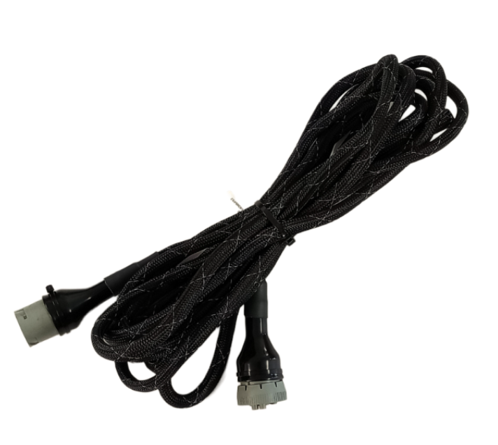](https://docs.t3rra.com/uploads/images/gallery/2026-09/e7oimage.png) 3\. Route the extension to the external valve block. Allow sufficient slack for tractor articulation and implement movement, and secure the harness clear of moving parts, hot surfaces and pinch points. 4\. Connect the **T3H-V003** valve adapter, or suitable alternative adapter, to the implement end of the **T3H-V002** extension. [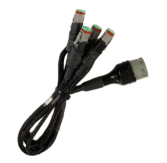](https://docs.t3rra.com/uploads/images/gallery/2026-09/d1Cimage.png) 5\. Connect the adapter’s solenoid plugs to the appropriate valve coils for each controlled function, such as height and cross-slope. Identify the raise/lower or tilt directions for verification during setup. 6\. Secure the connections and protect any unused connectors against moisture and dirt. 7\. Keep **COMMAND** disarmed and restore the electrical supply. ## Valve Configuration Confirm that the valve’s electrical requirements are compatible with **COMMAND** before operating the outputs. Refer to **Section 2.4** for proportional solenoid compatibility. [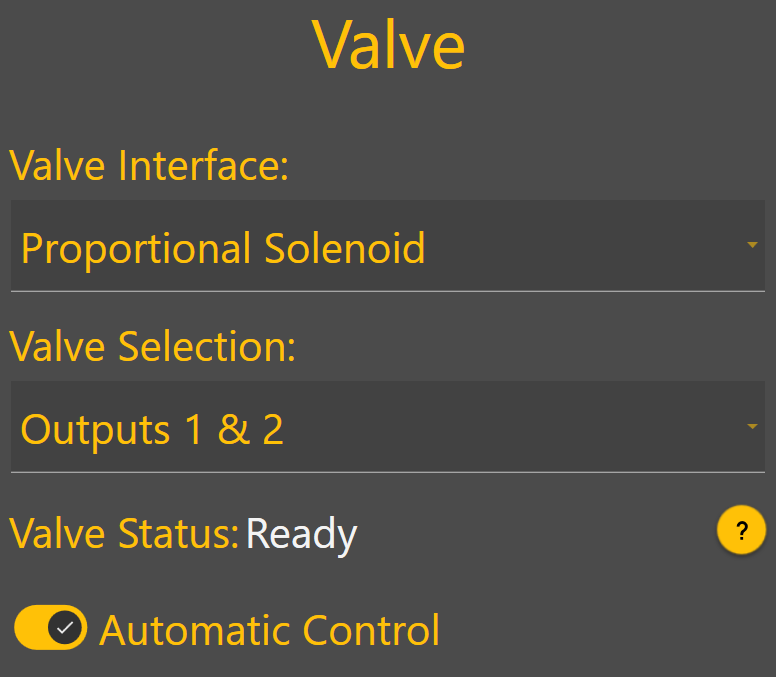](https://docs.t3rra.com/uploads/images/gallery/2026-09/gdHimage.png) In **Level COMMAND**: 1. Select **Proportional Solenoid** as the valve interface. 2. Assign the required valve outputs to each controlled function. 3. Verify that each function moves in the intended direction, then complete valve threshold and cylinder calibration. For detailed configuration and calibration instructions, refer to the **Level COMMAND Manual**.**NOTE:** The external valve block must have the hydraulic supply and return connections required by the implement manufacturer. Configure any tractor remote supplying the valve block according to those instructions.
## Operation Notes**NOTE:** If manual control is not already provided, install a compatible joystick as described in **Section 6.3**.
**COMMAND** must be armed for a connected joystick to operate the valve outputs. Use the **COMMAND Arm/Engage switch** to arm the system and engage automatic control. Joystick movement can disengage automatic control or temporarily override it, depending on the selected joystick configuration. Confirm the configured behaviour during commissioning and demonstrate it to the operator.**IMPORTANT:** To stop automatic control, press the momentary side of the **COMMAND Arm/Engage switch**. Move the switch to **OFF** to disarm **COMMAND** and disable its hydraulic control outputs. Disarming also disables valve operation from a COMMAND-connected joystick.
# 7.7 | Fendt ONE — 900 Gen 6/7 & 1000 Gen 2/3 **Applicable to:** Supported Fendt 900 Gen 6/7 and Fendt 1000 Gen 2/3 tractors using the **COMMAND Fendt ONE** valve interface. ## Connection Method **COMMAND** connects to the tractor’s rear SCV system using the **T3H-V005 ISO Valve Adapter**. The adapter is installed inline between the tractor chassis harness and the SCV-bank harness. It connects the tractor-side and valve-side CAN networks to **COMMAND** through the **CAN Interface** connection on the **T3H-C002** ECU breakout harness. The tractor connection is located at the rear of the machine, on the **right-hand side behind the ISOBUS socket**. ## Installation Steps [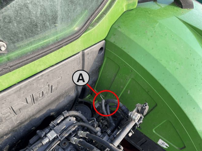](https://docs.t3rra.com/uploads/images/gallery/2026-09/hoaimage.png)1. Complete the machine preparation steps in **Section 5.1** and isolate the tractor electrical supply. 2\. Locate the SCV-bank harness connection behind the rear ISOBUS socket, shown as **A** in the location image. **(A) –** SCV / Chassis Harness connection [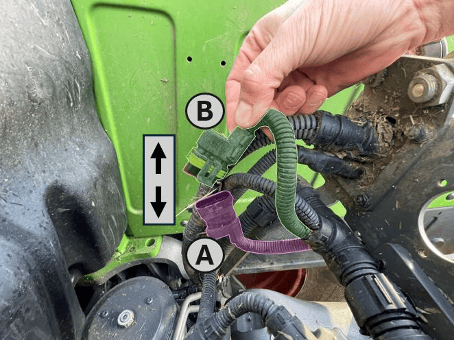](https://docs.t3rra.com/uploads/images/gallery/2026-09/Mb7image.png) 3\. Release the connector latch and disconnect the **SCV-bank harness receptacle (A)** from the **tractor chassis harness plug (B)**. **(A) –** SCV Bank Harness Receptacle **(B) –** Tractor Chassis harness plug [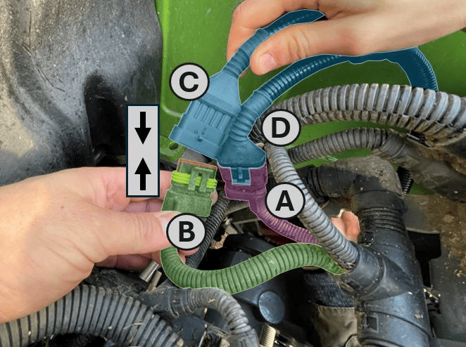](https://docs.t3rra.com/uploads/images/gallery/2026-09/BYqimage.png) 4\. Connect the **tractor-side receptacle (C)** on the **T3H-V005** adapter to the **tractor chassis harness plug (B)**. 5\. Connect the **valve-side plug (D)** on the **T3H-V005** adapter to the **SCV-bank harness receptacle (A)**. **(A)** – SCV Bank Harness Receptacle **(B)** – Tractor Chassis Harness Plug **(C)** – T3H-V005 Harness ‘Tractor’ Receptacle **(D)** – T3H-V005 Harness ‘Valve Block’ Plug [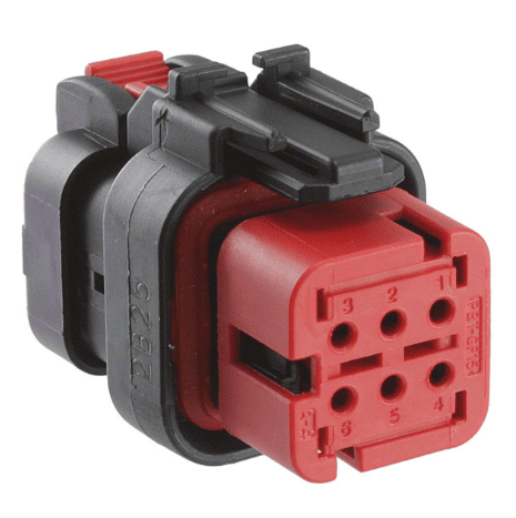](https://docs.t3rra.com/uploads/images/gallery/2026-09/9LAimage.png)6. Route the adapter to the **COMMAND** ECU and connect it to the **Tractor/Valve CAN Interface** connector (pictured right) on the **T3H-C002** ECU breakout harness. 7\. Ensure all connectors are fully seated and latched. Secure the harness clear of moving parts, hot surfaces and sharp edges, leaving sufficient slack to avoid strain on the connectors. 8\. Keep **COMMAND** disarmed and restore the electrical supply.**IMPORTANT:** The SCV-bank harness connection and the nearby ISOBUS socket connection serve different purposes. Connect **T3H-V005** to the SCV-bank harness as shown.
Where an ISOBUS connection is required for the installation, follow **Section 5.4** using the appropriate **COMMAND** cab or exterior breakout harness.
## Tractor Valve Configuration 1. Ensure the required tractor SCVs are enabled and unlocked using the tractor’s controls. 2. In **Level COMMAND**, select **Fendt ONE** as the valve interface. 3. Assign the required SCVs to the controlled functions, such as height and cross-slope. These assignments must match the implement’s hydraulic hose connections. 4. Verify valve communication and confirm that each function operates the intended valve in the correct direction. 5. Complete valve configuration and calibration before automatic operation. For detailed configuration and calibration instructions, refer to the **Level COMMAND Manual**. ## Operation Notes To prepare the selected SCVs for automatic control: 1. Ensure the required tractor SCVs are enabled and unlocked. 2. Move the **COMMAND Arm/Engage switch** to the middle **ON** position to arm COMMAND. 3. Move each selected SCV’s tractor control lever into the **float position** to enable external control of that valve. 4. Press the momentary side of the **COMMAND Arm/Engage switch** to engage automatic control once the system is ready.**NOTE:** For SCVs configured for **COMMAND** control, the lever’s **float position** enables external hydraulic control. It does **not** place the valve into hydraulic float.
Before handing over the installation, verify manual valve operation and demonstrate how to enable, disengage and resume automatic control.**IMPORTANT:** To disengage **COMMAND** automatic control, press the momentary side of the **COMMAND Arm/Engage switch**. Move the switch to **OFF** to disarm **COMMAND** and disable its hydraulic control commands.
# 7.8 | Fendt 800 SCR/S4 **Applicable to:** Supported Fendt 800 SCR/S4 tractors using the **COMMAND Fendt SCR/S4/MT** valve interface. ## Connection Method **COMMAND** connects to the tractor’s rear SCV system using the **T3H-V005 ISO Valve Adapter** and the **S/109 — Fendt 800 SCR/S4 Adapter Harness**, specified for SolSteer kit **K/SCV/008**. The **S/109** harness is installed inline between the tractor chassis harness and the valve harness. It connects to **T3H-V005**, which routes the tractor-side and valve-side CAN networks to the **CAN Interface** connection on the **T3H-C002** ECU breakout harness. The tractor connection consists of a pair of **4-way connectors**, located behind the panel under the **rear-right wheel arch**.**NOTE:** Depending on the tractor specification, an additional valve harness may be connected in series, providing two identical connections in this harness chain. Either of these connections can be used.
## Installation Steps 1\. Complete the machine preparation steps in **Section 5.1** and isolate the tractor electrical supply. [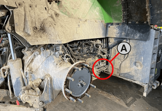](https://docs.t3rra.com/uploads/images/gallery/2026-09/OZdimage.png) 2\. Locate the valve/chassis harness connection behind the panel under the rear-right wheel arch, shown as **A** in the location image. [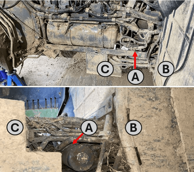](https://docs.t3rra.com/uploads/images/gallery/2026-09/dRZimage.png) 3\. Alternatively, it may be accessed from underneath the machine **(A)** – the bundle can be found amongst the hydraulic lines between the front of the wheel arch **(B)** and the valve block bracket **(C)**. **(A)** - Valve/Tractor Harness bundle **(B)** - Front of the Rear Right Wheel Arch **(C)** - Valve Bracket, behind Rear Right Wheel [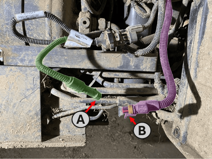](https://docs.t3rra.com/uploads/images/gallery/2026-09/XV4image.png) 3\. Release the connector latch and disconnect the **4-way valve harness receptacle (A)** from the **tractor chassis harness plug (B)**. [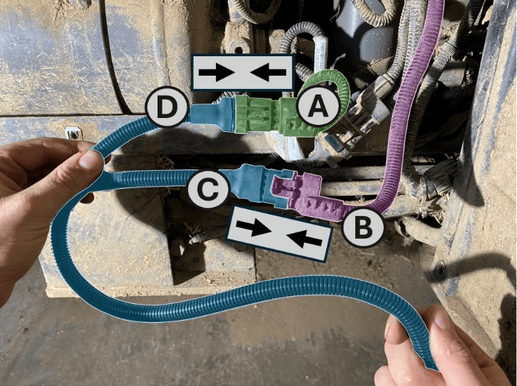](https://docs.t3rra.com/uploads/images/gallery/2026-09/R5oimage.png) 4\. Connect the **4-way “Tractor” receptacle (C)** on the **S/109** harness to the **tractor chassis harness plug (B)**. 5\. Connect the **4-way “Valve” plug (D)** on the **S/109** harness to the **valve harness receptacle (A)**. **(A)** – Receptacle on Machine Valve Harness **(B)** – Plug on Tractor Chassis Harness **(C)** – ‘Tractor’ Receptacle on S/109 Adaptor Harness **(D)** – ‘Valve’ Plug on S/109 Adaptor Harness 6\. Route the **S/109** harness towards the rear of the tractor. 7\. Connect the **5-way receptacle** on the **S/109** harness to the **valve-side plug** on **T3H-V005**. 8\. Connect the **5-way plug** on the **S/109** harness to the **tractor-side receptacle** on **T3H-V005**. 9\. Route **T3H-V005** to the **COMMAND** ECU and connect it to the **CAN Interface** connector on the **T3H-C002** ECU breakout harness. 10\. Ensure all connectors are fully seated and latched. Secure the harness clear of the tyre, moving parts, hot surfaces and sharp edges, leaving sufficient slack to avoid strain on the connectors. 11\. Refit any components removed for access. Keep **COMMAND** disarmed and restore the electrical supply.**IMPORTANT:** The valve-harness connection and the connection at the rear ISOBUS socket serve different purposes. Connect **S/109** to the valve/chassis harness connection identified above.
Where an ISOBUS connection is required for the installation, follow **Section 5.4** using the appropriate **COMMAND** cab or exterior breakout harness.
## Tractor Valve Configuration 1. Ensure the required tractor SCVs are enabled and unlocked using the tractor’s controls. 2. In **Level COMMAND**, select **Fendt SCR/S4/MT** as the valve interface. 3. Assign the required SCVs to the controlled functions, such as height and cross-slope. These assignments must match the implement’s hydraulic hose connections. 4. Prepare the selected SCVs for external control as described below, then verify that each function operates the intended valve in the correct direction. 5. Complete valve configuration and calibration before automatic operation. For detailed configuration and calibration instructions, refer to the **Level COMMAND Manual**. ## Operation Notes To prepare the selected SCVs for automatic control: 1. Ensure the required tractor SCVs are enabled and unlocked. 2. Move the **COMMAND Arm/Engage switch** to the middle **ON** position to arm COMMAND. 3. Move each selected SCV’s tractor control lever into the **float position** to enable external control of that valve. 4. Press the momentary side of the **COMMAND Arm/Engage switch** to engage automatic control once the system is ready.**NOTE:** For SCVs configured for **COMMAND** control, the lever’s **float position** enables external hydraulic control. It does **not** place the valve into hydraulic float.
**IMPORTANT:** To disengage **COMMAND** automatic control, press the momentary side of the **COMMAND Arm/Engage switch**. Move the switch to **OFF** to disarm **COMMAND** and disable its hydraulic control commands.
Before handing over the installation, verify manual valve operation and demonstrate how to enable, disengage and resume automatic control. # 7.9 | Fendt 900 SCR/S4 **Applicable to:** Supported Fendt 900 SCR/S4 tractors using the **COMMAND Fendt SCR/S4/MT** valve interface. ## Connection Method **COMMAND** connects to the tractor’s rear SCV system using the **T3H-V005 ISO Valve Adapter** and the **S/111 — Fendt 900 S4/SCR Adapter Harness**. The **S/111** harness is installed inline between the tractor chassis harness and the valve harness. It connects to **T3H-V005**, which routes the tractor-side and valve-side CAN networks to the **Tractor & Valve CAN Interface** 6-way connection on the **T3H-C002** ECU breakout harness. ## Installation Steps**NOTE:** The connection may be accessed from beneath the tractor, between the front of the rear-right wheel arch and the valve-block bracket. Removing the rear-right wheel and access panel provides additional access where required; follow the tractor manufacturer’s service instructions.
1\. Complete the machine preparation steps in **Section 5.1** and isolate the tractor electrical supply. [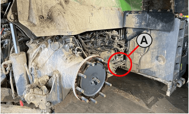](https://docs.t3rra.com/uploads/images/gallery/2026-09/Uzeimage.png)2. Locate the valve/chassis harness connection behind the panel under the rear-right wheel arch, shown as **A** in the location image. **(A)** - Valve/chassis harness connection [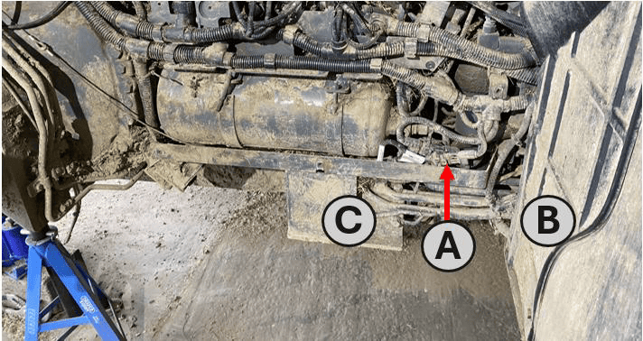](https://docs.t3rra.com/uploads/images/gallery/2026-09/7Avimage.png) 3\. Release the connector latch and disconnect the **valve harness receptacle (A — X1587\_P)** from the **tractor chassis harness plug (B — X1586\_S)**. **(A)** - Valve/Chassis Harness connection **(B)** - Front of the Rear Right Wheel Arch **(C)** - Valve Bracket, Inside Rear Right Wheel [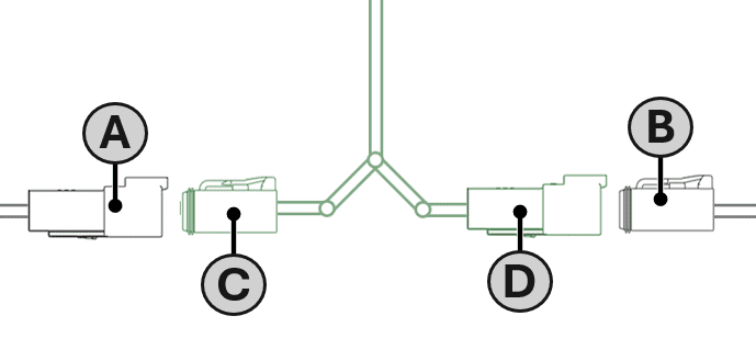](https://docs.t3rra.com/uploads/images/gallery/2026-09/XD1image.png) 4\. Connect the **4-way “VALVES” plug (C)** on the **S/111** harness to the **valve harness receptacle (A)**. **(A)** - Valve harness receptacle (X1587\_P) **(B)** - Chassis harness plug (X1586\_S) **(C)** - ‘VALVES’ Plug S/111 Adaptor Harness **(D)** - ‘TRACTOR’ Receptacle S/111 Adaptor Harness 5\. Connect the **4-way “TRACTOR” receptacle (D)** on the **S/111** harness to the **tractor chassis harness plug (B)**. 6\. Connect the **5-way plug** on the **S/111** harness to the **tractor-side receptacle** on **T3H-V005**. 7\. Connect the **5-way receptacle** on the **S/111** harness to the **valve-side plug** on **T3H-V005**. 8\. Route **T3H-V005** to the **COMMAND** ECU and connect it to the **CAN Interface** connector on the **T3H-C002** ECU breakout harness. 9\. Ensure all connectors are fully seated and latched. Secure the harness clear of the tire, moving parts, hot surfaces and sharp edges, leaving sufficient slack to avoid strain on the connectors. 10\. Refit any components removed for access. Keep **COMMAND** disarmed and restore the electrical supply.**IMPORTANT:** The 4-way valve-harness connection and the 4-way connection at the rear ISOBUS socket serve different purposes. Connect **S/111** to the valve/chassis harness connection identified above.
Where an ISOBUS connection is required for the installation, follow **Section 5.4** using the appropriate **COMMAND** cab or exterior breakout harness.
## Tractor Valve Configuration 1. Ensure the required tractor SCVs are enabled and unlocked using the tractor’s controls. 2. In **Level COMMAND**, select **Fendt SCR/S4/MT** as the valve interface. 3. Assign the required SCVs to the controlled functions, such as height and cross-slope. These assignments must match the implement’s hydraulic hose connections. 4. Prepare the selected SCVs for external control as described below, then verify that each function operates the intended valve in the correct direction. 5. Complete valve configuration and calibration before automatic operation. For detailed configuration and calibration instructions, refer to the **Level COMMAND Manual**. ## Operation Notes To prepare the selected SCVs for automatic control: 1. Ensure the required tractor SCVs are enabled and unlocked. 2. Move the **COMMAND Arm/Engage switch** to the middle **ON** position to arm COMMAND. 3. Move each selected SCV’s tractor control lever into the **float position** to enable external control of that valve. 4. Press the momentary side of the **COMMAND Arm/Engage switch** to engage automatic control once the system is ready.**NOTE:** For SCVs configured for **COMMAND** control, the lever’s **float position** enables external hydraulic control. It does **not** place the valve into hydraulic float.
**IMPORTANT:** To disengage **COMMAND** automatic control, press the momentary side of the **COMMAND Arm/Engage switch**. Move the switch to **OFF** to disarm **COMMAND** and disable its hydraulic control commands.
Before handing over the installation, verify manual valve operation and demonstrate how to enable, disengage and resume automatic control. # 7.10 | Fendt / Challenger MT **Applicable to:** Supported Fendt and Challenger MT tractors using the **COMMAND Fendt SCR/S4/MT** valve interface. ### Connection Method **COMMAND** connects to the tractor’s rear SCV system using the **T3H-V005 ISO Valve Adapter** and the **S/082 — Fendt/Challenger MT Adapter Harness**. The **S/082** harness is installed inline between the tractor chassis harness and the SCV-bank harness. It connects to **T3H-V005**, which routes the tractor-side and valve-side CAN networks to the **Tractor & Valve CAN Interface** connection on the **T3H-C002** ECU breakout harness. The tractor connection is located at the **rear-left of the machine**. The SCV-bank harness receptacle is a **flange-mounted 12-way Deutsch connector**, secured to a bracket behind the SCV bank. ### Installation Steps 1\. Complete the machine preparation steps in **Section 5.1** and isolate the tractor electrical supply. 2\. Connect the **5-way plug** on the **S/082** harness to the **tractor-side receptacle** on **T3H-V005**. 3\. Connect the **5-way receptacle** on the **S/082** harness to the **valve-side plug** on **T3H-V005**. [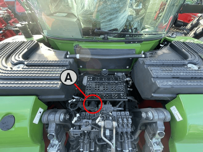](https://docs.t3rra.com/uploads/images/gallery/2026-09/avGimage.png) 4\. Locate the 12-way SCV-bank harness connection at the rear-left of the tractor. **(A)** - SCV Bank Harness connections [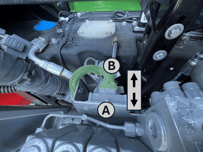](https://docs.t3rra.com/uploads/images/gallery/2026-09/Fqzimage.png) 5\. Release the connector latch and disconnect the **tractor chassis harness plug (B)** from the **SCV-bank harness receptacle (A)**. **(A)** – SCV Bank Harness Receptacle **(B)** – Tractor Chassis Harness Plug 6\. Connect the **tractor chassis harness plug (B)** to the **12-way “Tractor” receptacle (D)** on the **S/082** harness. 7\. Connect the **12-way “Implement PCB” plug (C)** on the **S/082** harness to the **SCV-bank harness receptacle (A)**. **(A)** – SCV Bank Harness Receptacle **(B)** – Tractor Chassis Harness Plug **(C)** – Implement PCB Plug, S/082 Harness Adaptor **(D)** – Tractor Receptacle, S/082 Harness Adaptor [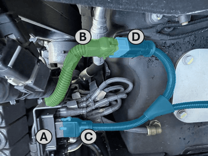](https://docs.t3rra.com/uploads/images/gallery/2026-09/hGMimage.png) 8\. Route **T3H-V005** to the **COMMAND** ECU and connect it to the **CAN Interface** connector on the **T3H-C002** ECU breakout harness. 9\. Ensure all connectors are fully seated and latched. Secure the harness clear of moving parts, hot surfaces and sharp edges, leaving sufficient slack to avoid strain on the connectors. 10\. Keep **COMMAND** disarmed and restore the electrical supply.**IMPORTANT:** The 12-way SCV-bank harness connection and the connection at the rear ISOBUS socket serve different purposes. Connect **S/082** to the SCV-bank harness connection identified above.
Where an ISOBUS connection is required for the installation, follow **Section 5.4** using the appropriate **COMMAND** cab or exterior breakout harness. ### Tractor Valve Configuration 1. Ensure the required tractor SCVs are enabled and unlocked using the tractor’s controls. 2. In **Level COMMAND**, select **Fendt SCR/S4/MT** as the valve interface. 3. Assign the required SCVs to the controlled functions, such as height and cross-slope. These assignments must match the implement’s hydraulic hose connections. 4. Prepare the selected SCVs for external control as described below, then verify that each function operates the intended valve in the correct direction. 5. Complete valve configuration and calibration before automatic operation. For detailed configuration and calibration instructions, refer to the **Level COMMAND Manual**. ### Operation Notes To prepare the selected SCVs for automatic control: 1. Ensure the required tractor SCVs are enabled and unlocked. 2. Move the **COMMAND Arm/Engage switch** to the middle **ON** position to arm COMMAND. 3. Move each selected SCV’s tractor control lever into the **float position** to enable external control of that valve. 4. Press the momentary side of the **COMMAND Arm/Engage switch** to engage automatic control once the system is ready.**NOTE:** For SCVs configured for COMMAND control, the lever’s **float position** enables external hydraulic control. It does **not** place the valve into hydraulic float.
**IMPORTANT:** To disengage **COMMAND** automatic control, press the momentary side of the **COMMAND Arm/Engage switch**. Move the switch to **OFF** to disarm **COMMAND** and disable its hydraulic control commands.
Before handing over the installation, verify manual valve operation and demonstrate how to enable, disengage and resume automatic control. # 8 | Receiver Connection and Configuration (GNSS) Connecting various GNSS receivers for operation with COMMAND # 8.1 | Modern NMEA 2000 (Case, New Holland, Trimble) This section covers connection of Novatel-based GNSS receivers using a 12-pin Deutsch interface. **Applicable to receivers including:** Case IH - Vector Pro New Holland - PLM Cygnus Trimble / PTx Trimble - AG-372, AG-392, NAV-900, NAV-960 Steyr - S-Guide [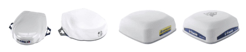](https://docs.t3rra.com/uploads/images/gallery/2026-07/NYR6G2QZm2Kn3gr7-image.png) ## Parts Required - **CNH 115-7100-009/10 - **Front Extension Harness **or** **JD BPF11284 - **Front Extension Harness - **CNH 115-7100-005** - Cable Adapter Terminator Gen I ISOBUS **or JD PF81137** - Implement Pigtail Terminator Wiring Harness - **T3H-G002** - COMMAND Impl Adapter - NAV-900 - **T3H-S001** - COMMAND Impl Adapter – Stub Junction ## Connection Process 1\. Connect the Front Extension Harness to the ISOBUS breakaway connection. [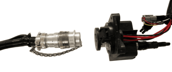](https://docs.t3rra.com/uploads/images/gallery/2025-07/AsF8TBsTh5FtRUiE-image.png) 2\. Route along the implement, allowing slack at pivot points and avoiding snag hazards. 3\. Connect the **T3H-S001** adapter to the Front Extension Harness. [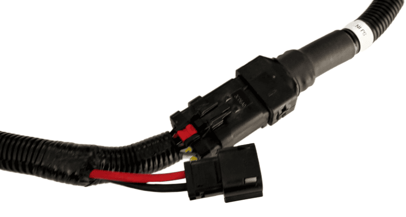****](https://docs.t3rra.com/uploads/images/gallery/2025-07/SuU4oxt2DKiArihK-image.png) 4\. Connect the Implement Pigtail Terminator to the **T3H-S001** adapter and secure the terminator to the implement receiver wiring harness. [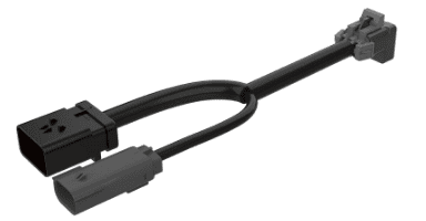](https://docs.t3rra.com/uploads/images/gallery/2025-07/xGDljli6p8S80NtF-image.png) 5\. Connect the **T3H-G002** adapter to the **T3H-S001** adapter. [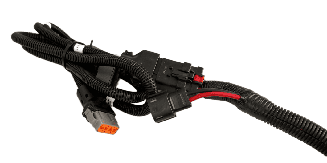](https://docs.t3rra.com/uploads/images/gallery/2025-07/JKqGyH4UW8wofgXl-image.png) 6\. Connect the **T3H-G002** adapter to the appropriate GNSS receiver port. 7\. If using NMEA 0183 Serial, also connect the NMEA extension harness to the **T3H-G002**, then connect the other end to the **T3H-C002** ECU breakout harness. **Verify:** \- Receiver powers on # 8.2 | Trimble FMX/GFX/TMX with Ag25 **Applicable to:** Trimble FMX, GFX, and TMX displays using NMEA 0183 RS232 output via 12-way DTM port. ## Harnessing Layout Overview Usage of the FMX/TMX NMEA 0183 output only requires the addition of a **T3H-G004** adapter to the **T3H-C002** ECU breakout harness. [ ](https://docs.t3rra.com/uploads/images/gallery/2025-06/bjvGafxmKnL93858-image.png) ## Parts Required - **T3H-G004** - COMMAND Trimble NMEA Output Adapter ## Connection Process**NOTE:** The **T3H-G004** adapter routes the RS232 Tx and Rx connection to the **COMMAND** ECU and they are NOT replicated on the port replicator connector. All other pins are replicated for connection of other devices.
#### For FMX/FM1000 Connect the **T3H-G004** adapter to Port C or Port D on the FMX display depending on whether antenna port 1 or 2 is to be used. Port C will provide the NMEA output for antenna port 1 while Port D will provide NMEA output for antenna port 2. [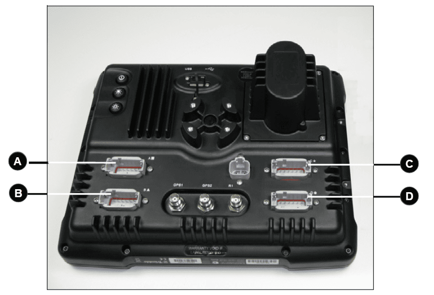](https://docs.t3rra.com/uploads/images/gallery/2025-07/gv3g0LjujVC6TfsI-image.png) #### For GFX/TMX with TM-200 and EXP-100 Connect the T3H-G004 adapter to the EXP-100 port expander module. [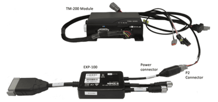](https://docs.t3rra.com/uploads/images/gallery/2025-07/1femlJZ3ZAH8QE9L-image.png) A port replicator is supplied in case the port was already in use for something else, if so disconnect the device, connect **T3H-G004** and then reconnect the device using the port replicator on **T3H-G004.** [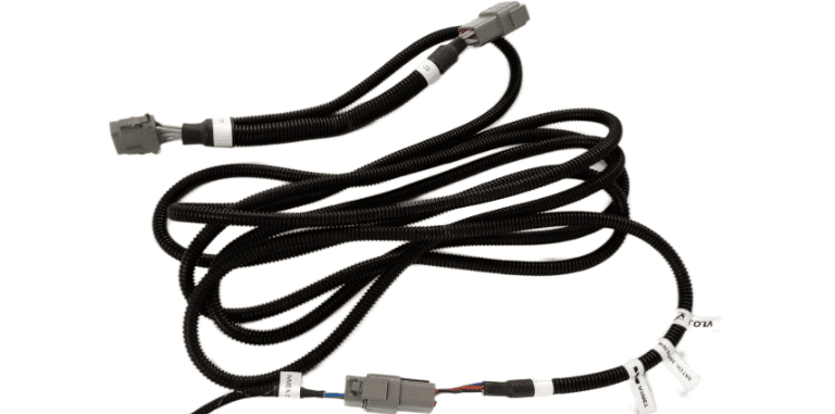](https://docs.t3rra.com/uploads/images/gallery/2025-07/xxawJnUqq8xMDqhC-image.png) Connect the other end of **T3H-G004** to the **T3H-C002** ECU breakout harness. [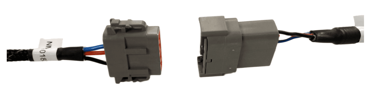](https://docs.t3rra.com/uploads/images/gallery/2025-07/csTqSFz0mjgZA4Hw-image.png) Next, follow the setup process below for activating the NMEA output port on the FMX/TMX system. ## Activating the NMEA Output - FMX/FM1000 Make sure that if present, Autopilot is configured for use on Port A - this leaves Port C and Port D free for NMEA output of either implement receiver. 1\. Select the GPS Receiver listed below Autopilot \[Vehicle\] and press "Setup". 2\. Press the "GPS Output" button. 3\. Configure the NMEA GPS Output port as below: - Select Output Port A (ext. GPS) - Select a message rate of 5 Hz - Select a Baud Rate of 38400 - Set Maximum GGA Quality to 0 - Set Lat/Lon Precision to 8 - Press the "NMEA Messages" Tab. 4\. Configure the NMEA Messages as below: - Set GGA, to "On". - Set GSA, to "On". - Set VTG, to "On". - Leave all other messages set to "Off". [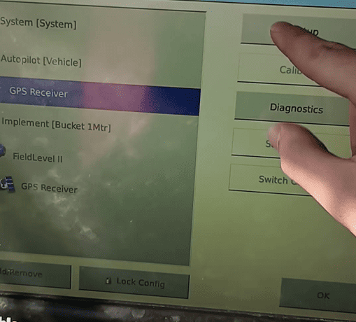](https://docs.t3rra.com/uploads/images/gallery/2025-07/1eCDkWpS6dI6xoug-image.png) [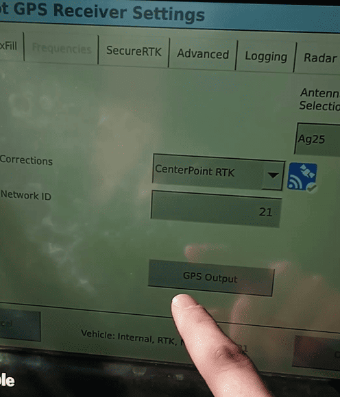](https://docs.t3rra.com/uploads/images/gallery/2025-07/Di4SgRz29gVvrUIJ-image.png) [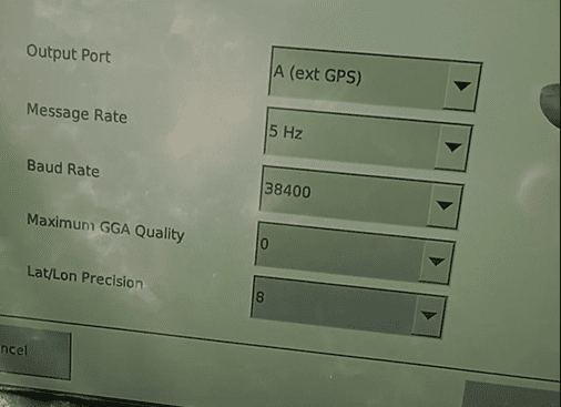](https://docs.t3rra.com/uploads/images/gallery/2025-07/IG2n3zXiNXJzWaCS-image.png) [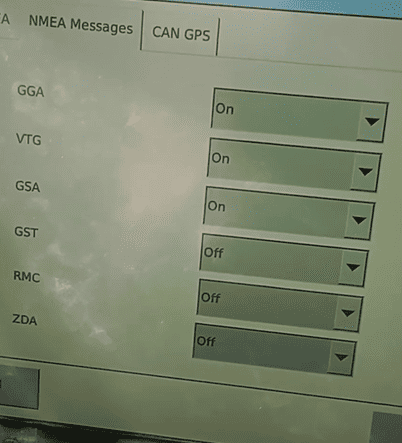](https://docs.t3rra.com/uploads/images/gallery/2025-07/puLZoHxvb9qXPnNH-image.png) # 8.3 | NMEA 0183 (RS232) NMEA 0183 Serial (RS232) capable receivers can be connected to the **COMMAND** system.**IMPORTANT:** If the GNSS receiver does not provide terrain compensation, an IMU must be installed to maintain accuracy.
## Parts Required - **CNH 115-7100-009/10 -** Front Extension Harness or** **JD BPF11284 -** Front Extension Harness - **CNH 115-7100-005** - Cable Adapter Terminator Gen I ISOBUS **or JD** **PF81137 - **Implement Pigtail Terminator Wiring Harness - **T3H-S001** - COMMAND Impl Adapter – Stub Junction - **T3H-G001 / T3H-G007** - COMMAND NMEA Extension Harness (8m or 12m) - **Custom GNSS Adapter** - Custom adapter for connection of the NMEA 0183 Serial compatible receiver to the **T3H-S001** and **T3H-G001/G007** adapters. ## Connection Process 1\. Connect the Front Extension Harness to the ISOBUS breakway connector. 2\. Route along the implement, allowing slack at pivot points and avoiding snag hazards. **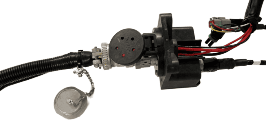**3. Connect the **T3H-S001** adapter to the Front Extension Harness. **[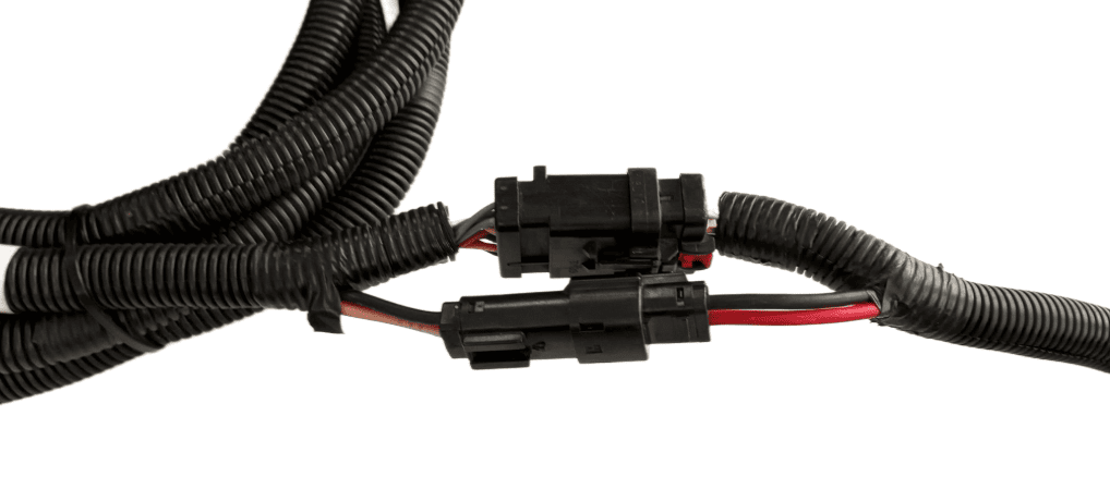](https://docs.t3rra.com/uploads/images/gallery/2025-07/szCk65qzjfDIekAM-image.png)** 4\. Connect the Implement Pigtail Terminator to the Implement Receiver Wiring Harness and secure the terminator to the implement receiver wiring harness. [](https://docs.t3rra.com/uploads/images/gallery/2025-07/xGDljli6p8S80NtF-image.png) 5\. Connect the **CUSTOM** adapter to the **T3H-S001** adapter. 6\. Connect the **CUSTOM** adapter to the receiver's port ensuring connector keys are lined up. 7\. Connect the NMEA extension harness **T3H-G001** or **T3H-G007** to the **CUSTOM adapter, then connect the other end to the **T3H-C005** external breakout harness. ## Receiver Configuration Perform necessary setup of the GNSS receiver using provided manufacturer tools or programs: - - Talker ID should be set to GP or GN - Messages enabled - GGA, GSA, VTG - Output Update rate - 10Hz recommended - Baud Rate - 38400 **Verify:** \- Receiver powers on # 8.4 | John Deere StarFire **Applicable to:** John Deere StarFire 3000, 6000, 7000 & 7500 GNSS receivers using implement harnessing. ## Harnessing Layout Overview[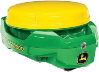](https://docs.t3rra.com/uploads/images/gallery/2025-07/d0ZqDnp82Bg2PBuV-ecu-jd-starfire7000.png) For use with **COMMAND**, the John Deere StarFire can be set up with typical John Deere implement harnessing: - **RE174726 -** Greenstar ISOBUS IBBC (Implement Bus Breakaway Connector) if not present, IBBC from other manufacturers are also appropriate for **COMMAND**. - **BPF11117 -** John Deere Front Extension Harness with Terminator (10m) - **OR BPF11284** - John Deere Front Extension Harness (10m) - **AND PF81137** - John Deere Implement Pigtail Terminator Wiring Harness - **PF90538** - John Deere Implement Receiver Wiring Harness Kit [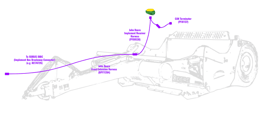](https://docs.t3rra.com/uploads/images/gallery/2025-06/llg75Ge3jUSyWMMy-image.png) ## Connection Process[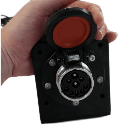](https://docs.t3rra.com/uploads/images/gallery/2025-07/OTR1gMZOtLaxdVLj-image.png) 1\. Connect the John Deere Front Extension Harness to the ISOBUS breakaway connection. 2\. Route along the implement, allowing slack at pivot points and avoiding snag hazards. [](https://docs.t3rra.com/uploads/images/gallery/2025-07/VMiw0b4MueoRx1Ti-image.png) 3\. Connect the Implement Receiver Wiring Harness to the Front Extension Harness and route the cabling up toward the receiver mast. [](https://docs.t3rra.com/uploads/images/gallery/2025-07/szCk65qzjfDIekAM-image.png) 4\. Connect the Implement Receiver Wiring Harness to the Starfire receiver 12-pin DT connector. A 12-pin Deutsch gender change adapter may be needed to connect the DT06-12SA connector on the implement receiver harness to the DT06-12SA connector on the StarFire Receiver. [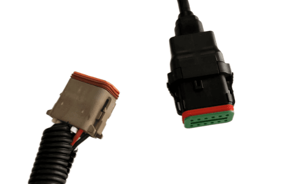](https://docs.t3rra.com/uploads/images/gallery/2025-07/3C3yWqNDgx6pp3hT-image.png) 5\. Connect the **PF81137 **Implement Pigtail Terminator to the Implement Receiver Wiring Harness and secure the terminator to the implement receiver wiring harness. [](https://docs.t3rra.com/uploads/images/gallery/2025-07/xGDljli6p8S80NtF-image.png) **Verify:** \- Receiver powers on # 9 | IMU Installation and Configuration This section covers installation and configuration of terrain compensation systems used with **COMMAND**. Installing an Inertial Measurement Unit (IMU) allows **Level COMMAND** to perform terrain compensation and additionally, enable cross slope control with a single GNSS receiver. If using a StarFire receiver, the internal Terrain Compensation Module (TCM) can be configured for this application. # 9.1 | TARS-B IMU (T3H-E003) **Applicable to:** Systems where the GNSS receiver does not provide terrain compensation and/or Cross-slope control is required.**IMPORTANT:** Some GNSS receivers DO NOT possess an internal IMU for terrain compensation purposes. If the receiver doesn't have terrain compensation, we highly recommend running a Cross-slope IMU on the implement in this situation so that Level **COMMAND** can apply the necessary terrain compensation to maintain accuracy with drain batters and other steeper slopes.
**IMPORTANT:** The TARS-B IMU must be sourced from T3RRA (SKU: **T3H-E003**). These are supplied by T3RRA with the correct firmware and configuration to function with **COMMAND**.
The TARS-B IMU is used for systems where the GNSS receiver does not contain an integrated terrain compensation functionality, in addition to enabling Cross-slope control using **COMMAND**. The TARS-B IMU provides pitch and roll angle measurements to the **COMMAND** ECU for control of the implement's Cross-slope angle. ## Required Parts The IMU connects via the implement receiver harnessing. - Front Extension harness - TARS-B Mounting Kit (3 x M6 + Washer + Nut) - **T3H-E003** - COMMAND Inclination Sensor – TARS-B - **T3H-S001** - COMMAND Impl Adapter – Stub Junction ### [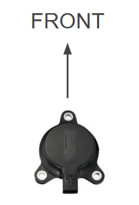](https://docs.t3rra.com/uploads/images/gallery/2025-06/q0hFVRBkx0MRdpye-image.png) ## Mounting & Orientation The TARS-B IMU should be mounted pointing toward the front of the machine, similar to an arrow or triangle pointing forwards. Mount the TARS-B IMU to the implement securely, preferably using a suitable bracket. If suitable bracketing isn't available, neodymium magnets are also suitable, but must have enough pull-strength that there is minimal danger of the IMU being knocked out of position. ## Connection Process 1. Connect the **T3H-S001** adapter to the Front Extension Harness. 2. Connect the **T3H-E003** to the **T3H-S001** stub junction using the 4-way AMPSEAL connection. 3. Check that **COMMAND** is receiving Cross-slope angle input data - for more information please refer to the **Level COMMAND** manual. **Verify:** \- IMU is securely aligned, mounted and connected. # 9.2 | John Deere StarFire TCM (3000, 6000, 7000, 7500) **Applicable to:** John Deere StarFire 3000, 6000, 7000 & 7500 receivers with integrated Terrain Compensation Module (TCM). ## StarFire TCM Overview Modern John Deere StarFire GNSS Receivers contain an integrated Terrain Compensation Module (TCM) that measures pitch/roll angle position of the receiver, and calculates adjustments to GNSS position based on the angle of the receiver to provide the true ground point position, provided that receiver offsets have been entered correctly. [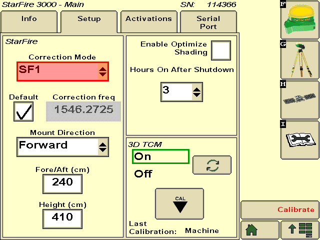](https://docs.t3rra.com/uploads/images/gallery/2025-06/DUTthllVQg5aBX4m-greenstar-starfire-tcmcal.png) ## Configuration Overview 1\. Enable the 3D TCM setting in the StarFire receiver. 2\. Enter correct receiver offsets (fore/aft and height). 3\. Perform TCM calibration as per John Deere guidelines. 4\. Verify TCM status is active. For more guidance on best practices and setting up the StarFire TCM, please refer to John Deere's Starfire Operator Manual. # 10 | Troubleshooting This section provides basic troubleshooting information for common **COMMAND** installation and operation issues. # 10.1 | Overview **Before troubleshooting:** \- Confirm all system components are correctly installed \- Verify all connectors are fully seated and undamaged \- Ensure the system has been configured correctly within **Level COMMAND** \- Confirm all machine power and hydraulic systems are operating normally If an issue cannot be resolved using the information below, contact T3RRA support. # 10.2 | GNSS & Position Issues| **Issue** | **Possible Cause** | **Recommended Action** |
| No GNSS position detected | Receiver harness disconnected | Verify GNSS receiver harness connections |
| No GNSS position detected | Receiver not powered | Verify GNSS receiver/display powers on correctly |
| No GNSS data after startup | Receiver still initialising | Allow receiver sufficient time to initialise and acquire satellite lock |
| Receiver powers on but no data detected | Incorrect receiver output connection or configuration | For NMEA 2000 receivers, verify connection to the correct CANBUS port operating at 250 kbps. For NMEA 0183 receivers, verify the correct serial output port and baud rate are configured and connected |
| Receiver powers on but no data detected | Incorrect RS232 baud rate configuration | For NMEA 0183 receivers, verify the configured serial baud rate matches the Level COMMAND receiver configuration |
| Receiver powers on but no data detected | Incorrect CANBUS connection or baud rate | For CANBUS/NMEA 2000 receivers, verify the receiver is connected to the correct CANBUS network operating at 250 kbps |
| Receiver powers on but no data detected | NMEA output messages not enabled | Verify required NMEA output messages are enabled within the receiver/display configuration |
| Position updates slowly | Low output rate configured | Configure receiver output rate to minimum 5 Hz; 10 Hz recommended |
| No RTK corrections | Incorrect base station selected | Verify the implement receiver is connected to the intended base station or correction source |
| No RTK corrections | Base station not transmitting corrections | Verify base station operation and correction output |
| No RTK corrections | Incorrect base station configuration | Verify base station radio/modem and correction output configuration |
| No RTK corrections | Incorrect implement receiver configuration | Verify correction source, radio/modem and RTK settings within the implement receiver |
| RTK intermittently lost | Poor correction radio signal | Inspect correction antenna placement and cable condition |
| RTK intermittently lost | Excessive distance from base station | Reduce distance to base station or verify correction coverage |
| RTK intermittently lost | GNSS quality thresholds configured too aggressively | Verify Level COMMAND GNSS requirement settings are suitable for current operating conditions |
| Poor accuracy or drifting | Low GNSS correction quality | Verify RTK/DGNSS correction status |
| Poor accuracy or drifting | Multipath or obstructed sky view | Move machine to open sky area clear of obstructions |
| GNSS accuracy degraded unexpectedly | Receiver operating in Float/DGNSS mode | Verify RTK Fix status before operation |
| Position intermittently lost | Damaged harness or loose connector | Inspect GNSS harnessing and connectors |
| Position quality degraded | Receiver firmware outdated | Verify GNSS receiver firmware is up to date |
| Position appears offset | Incorrect base station coordinates | Verify configured base station coordinates |
| Position appears offset | Connected to incorrect base station | Verify the implement receiver is connected to the correct base station |
| Position appears offset | Incorrect receiver offsets configured | Verify receiver height, fore/aft and lateral offsets within Level COMMAND |
| **Issue** | **Possible Cause** | **Recommended Action** |
|---|---|---|
| Cross-slope or terrain response incorrect | Receiver-integrated IMU/TCM not calibrated | Perform IMU/TCM calibration according to receiver manufacturer instructions |
| Cross-slope or terrain response incorrect | Receiver-integrated IMU/TCM disabled within receiver configuration | Verify IMU/TCM functionality is enabled within the GNSS receiver configuration |
| **Issue** | **Possible Cause** | **Recommended Action** |
|---|---|---|
| Cross-slope or terrain response incorrect | Sensor offsets not enabled | Verify sensor offsets are enabled within Level COMMAND |
| Cross-slope or terrain response incorrect | Incorrect sensor offsets configured | Verify IMU position offsets are correctly measured and configured within Level COMMAND |
| Cross-slope or terrain response incorrect | Incorrect IMU assignment or configuration | Verify the correct IMU source is configured within Level COMMAND |
| Terrain compensation unstable | TARS IMU mounted incorrectly | Verify IMU mounting orientation and mounting rigidity |
| **Issue** | **Possible Cause** | **Recommended Action** |
|---|---|---|
| No hydraulic movement | Valve harness disconnected | Verify all ECU and valve harness connections |
| No hydraulic movement | Incorrect hydraulic interface selected | Verify the configured hydraulic interface type within Level COMMAND |
| No hydraulic movement | Hydraulic outputs disabled | Verify COMMAND outputs are enabled and Automatic Control is Armed. Check valve status within COMMAND Settings > Valve Configs or COMMAND Settings > Tuning |
| No hydraulic movement | Tractor hydraulic remotes disabled | Verify tractor SCVs/remotes are enabled and assigned correctly |
| Raise/lower functions reversed | Incorrect valve polarity or hydraulic configuration | Verify hydraulic output polarity and configuration |
| Raise/lower functions reversed | Hydraulic hoses connected incorrectly | Verify hydraulic hose routing and plumbing orientation |
| Hydraulic outputs operate incorrectly | Incorrect valve type selected | Verify the configured hydraulic interface matches the installed valve system. Check valve status within COMMAND Settings > Valve Configs |
| Hydraulic outputs operate incorrectly | Incorrect CANBUS interface configuration | Verify CANBUS/J1939 hydraulic interface configuration |
| Hydraulic movement unstable | Incorrect calibration values | Recheck hydraulic calibration and tuning settings |
| Hydraulic movement unstable | Incorrect tuning parameter configuration | Verify minimum extend/retract thresholds, maximum extend/retract thresholds, tracking sensitivity and cylinder ratio settings |
| Hydraulic movement slow or unresponsive | Hydraulic flow limits too low | Verify tractor hydraulic flow settings |
| Hydraulic movement slow or unresponsive | Engine RPM too low | Operate machine at recommended engine RPM |
| Hydraulic movement delayed | Excessive deadband configuration | Verify deadband and response tuning settings |
| Hydraulic outputs noisy or erratic | Damaged PWM/analog wiring | Inspect hydraulic output harnessing for damage |
| Hydraulic calibration cannot be completed | Incorrect machine setup during calibration | Perform calibration on stable level ground |
| Hydraulic calibration cannot be completed | Incorrect valve wiring | Verify valve output wiring and polarity |
| Automatic Control disengages during operation | Hydraulic response outside configured limits | Verify hydraulic tuning and response stability |
| Automatic Control performance inconsistent | Incorrect implement profile selected | Verify correct implement configuration within Level COMMAND |
| Hydraulic movement continues after command released | Hydraulic valve sticking | Inspect hydraulic valve operation and cleanliness |
| Hydraulic movement continues after command released | Incorrect valve calibration | Recheck valve calibration settings |
| Hydraulic outputs noisy or erratic | Electrical noise or poor grounding | Verify ECU and valve grounds are secure |
| Hydraulic outputs noisy or erratic | Damaged PWM/analog wiring | Inspect hydraulic output harnessing for damage |
| Hydraulic outputs noisy or erratic | Incorrect PWM frequency configuration | Verify PWM frequency matches valve requirements |
| No external valve response | Incorrect VM430/431 configuration | Verify external valve controller setup and addressing |
| No external valve response | Incorrect J1939 configuration | Verify J1939 network settings and communication |
| Hydraulic response differs between directions | Unequal flow settings | Verify raise/lower hydraulic flow configuration |
| Hydraulic calibration cannot be completed | Incorrect machine setup during calibration | Perform calibration on stable level ground |
| Hydraulic calibration cannot be completed | Incorrect valve wiring | Verify valve output wiring and polarity |
| Automatic Control disengages during operation | Hydraulic response outside configured limits | Verify hydraulic tuning and response stability |
| Automatic Control performance inconsistent | Incorrect implement profile selected | Verify correct implement configuration within Level COMMAND |
| Issue | Possible Cause | Recommended Action |
|---|---|---|
| Joystick not detected | Joystick harness disconnected | Verify joystick harness connections and adapter installation |
| Joystick not detected | Incorrect joystick adapter used | Confirm the correct joystick adapter harness is installed |
| Joystick not detected | Joystick not powered | Verify joystick power supply and CANBUS/voltage supply |
| No joystick response | Incorrect joystick type selected | Verify joystick type configuration within COMMAND Settings > Valve Configs |
| No joystick response | Incorrect CANBUS connection | Verify joystick connection to the correct tractor CANBUS network |
| No joystick response | Incorrect joystick baud rate or CAN configuration | Verify joystick CANBUS/J1939 configuration |
| No joystick response | Incorrect analog input wiring | Verify analog joystick signal wiring and pinout |
| Analog joystick unstable | Incorrect voltage range | Verify joystick output voltages are within expected operating range |
| Analog joystick unstable | Electrical noise or poor grounding | Verify grounding and harness routing away from high-current wiring |
| Analog joystick unstable | Damaged potentiometer or joystick hardware | Inspect joystick operation and signal stability |
| Joystick response delayed | CANBUS communication delay | Verify CANBUS communication quality and network loading |
| Joystick response delayed | Incorrect filtering or response settings | Verify joystick response configuration within COMMAND Settings > Valve Configs |
| Raise/lower commands reversed | Incorrect joystick polarity or mapping | Verify joystick direction mapping and polarity configuration within COMMAND Settings > Valve Configs |
| Auxiliary joystick buttons not functioning | Incorrect button mapping | Verify auxiliary button assignments within COMMAND Settings > Valve Configs |
| Engage switch not detected | Incorrect engage switch wiring | Verify engage switch wiring and connector installation |
| Automatic Control will not Engage | Joystick not returning to neutral | Verify joystick neutral position and calibration |
| Automatic Control disengages unexpectedly | Engage switch issue | Verify engage switch operation and stability |
| Automatic Control disengages unexpectedly | Unintended joystick movement detected | Verify joystick mounting and operator input stability |
| Automatic Control disengages unexpectedly | Joystick calibration incorrect | Recheck joystick calibration within COMMAND Settings > Valve Configs |
| Joystick input intermittently lost | Loose connector or damaged harness | Inspect joystick harnessing and connectors |
| Joystick input intermittently lost | CANBUS termination or communication issue | Verify CANBUS network integrity and termination |
| Analog joystick calibration fails | Input voltage outside expected range | Verify joystick signal voltage and wiring |
| J1939 joystick not communicating | Incorrect CANBUS network selected | Verify joystick is connected to the intended tractor CANBUS |
| J1939 joystick not communicating | Unsupported joystick configuration | Verify joystick compatibility and configuration requirements |
| J1939 joystick buttons operate incorrectly | Incorrect button assignment configuration | Verify configured joystick button mappings within COMMAND Settings > Valve Configs |
| Operator input behaves inconsistently | Multiple input devices configured incorrectly | Verify only intended joystick/input devices are enabled |
| Operator input behaves inconsistently | Incorrect software configuration loaded | Verify the correct machine and joystick profile is selected |
| **Issue** | **Possible Cause** | **Recommended Action** |
|---|---|---|
| Cross-slope compensation not operating correctly | IMU disconnected | Verify IMU harness connections and power supply |
| Cross-slope compensation not operating correctly | IMU not enabled within Level COMMAND | Verify IMU functionality is enabled within Level COMMAND |
| Cross-slope control produces unexpected movement | Incorrect IMU orientation | Verify IMU orientation and mounting direction |
| Implement is not level while reporting 0° / 0% cross-slope | IMU mounted on angled surface | Mount IMU to a level reference surface aligned with the machine |
| Implement is not level while reporting 0° / 0% cross-slope | Incorrect sensor offsets configured | Verify sensor offsets are correctly measured and configured within Level COMMAND |
| Cross-slope angle displayed incorrectly | Incorrect IMU assignment or configuration | Verify the correct IMU source is configured within Level COMMAND |
| Reported cross-slope angle is unstable | Loose IMU mounting hardware | Verify IMU mounting hardware is secure |
| Reported cross-slope angle is unstable | IMU mounted on flexible surface | Mount IMU to a rigid surface isolated from excessive vibration |
| Reported cross-slope angle is erratic even when travelling over smooth ground | Excessive vibration at mounting location | Inspect IMU mounting location and machine vibration sources |
| Cross-slope compensation differs between passes | IMU mounting position shifted | Inspect IMU mounting and alignment |
| Cross-slope compensation differs between passes | GNSS correction quality unstable | Verify RTK/DGNSS correction status |
| Cross-slope compensation produces inconsistent results | Sensor offsets disabled | Verify sensor offsets are enabled within Level COMMAND |
| StarFire TCM calibration cannot be completed | Poor satellite visibility | Move machine to open sky area clear of obstructions |
| StarFire TCM calibration cannot be completed | Incorrect GNSS receiver configuration | Verify GNSS receiver operation and correction quality |
| StarFire TCM calibration cannot be completed | Excessive machine vibration during calibration | Perform calibration with machine stationary and hydraulics stable |
| IMU intermittently disconnects | Loose connector or damaged harness | Inspect IMU harnessing and connectors |
| IMU intermittently disconnects | CANBUS communication instability | Verify CANBUS network integrity and termination |
| Terrain compensation differs between passes | IMU mounting shifted | Inspect IMU mounting and alignment |
| Terrain compensation differs between passes | GNSS correction quality unstable | Verify RTK/DGNSS correction status |
| Automatic Control performance inconsistent on slopes | Cross-slope compensation disabled | Verify terrain compensation is enabled within Level COMMAND |
| Automatic Control performance inconsistent on slopes | Incorrect terrain compensation source selected | Verify the intended IMU/TCM source is configured |
| IMU intermittently disconnects | Loose connector or damaged harness | Inspect IMU harnessing and connectors |
| IMU intermittently disconnects | CANBUS communication instability | Verify CANBUS network integrity and termination |
| **Issue** | **Possible Cause** | **Recommended Action** |
|---|---|---|
| ISOBUS communication unavailable | ISOBUS harness disconnected | Verify ISOBUS harness connections and adapter installation |
| ISOBUS communication unavailable | Incorrect ISOBUS connection point | Verify COMMAND is connected to the tractor ISOBUS network |
| ISOBUS communication unavailable | Incorrect ISOBUS adapter used | Verify the correct ISOBUS adapter harness is installed |
| ISOBUS communication unavailable | ISOBUS network not powered | Verify the tractor ISOBUS network is active |
| Tractor CAN communication unavailable | Incorrect Tractor CAN connection | Verify COMMAND is connected to the intended Tractor CAN network |
| Tractor CAN communication unavailable | Incorrect Tractor CAN baud rate | Verify Tractor CAN baud rate configuration within Level COMMAND |
| Intermittent CANBUS virtual terminal or device dropouts | Loose connector or damaged harness | Inspect CANBUS harnessing and connectors |
| Intermittent CANBUS virtual terminal or device dropouts | Poor CANBUS termination | Verify correct CANBUS termination resistance and network layout |
| Intermittent CANBUS virtual terminal or device dropouts | Incorrect CANBUS network selected | Verify all CANBUS devices are connected to the intended network |
| GNSS receiver intermittently disconnects | CANBUS backbone or branch wiring issue | Inspect CANBUS backbone and branch harness connections |
| IMU intermittently disconnects | CANBUS backbone or branch wiring issue | Inspect CANBUS backbone and branch harness connections |
| SCV controller intermittently disconnects | CANBUS backbone or branch wiring issue | Inspect CANBUS backbone and branch harness connections |
| No communication with the SCV controller | Incorrect hydraulic interface selected | Verify the correct hydraulic interface is configured within Level COMMAND |
| No communication with the SCV controller | Incorrect SCV CAN baud rate | Verify SCV CAN baud rate configuration within Level COMMAND |
| No communication with the SCV controller | Unsupported tractor or SCV configuration | Verify tractor compatibility and supported hydraulic interface type |
| Tractor SCVs operate incorrectly | Incorrect hydraulic interface configuration | Verify configured hydraulic interface type and machine profile |
| CAN joystick not detected | Incorrect CANBUS connection | Verify joystick connection to the intended tractor CANBUS |
| CAN joystick not detected | Unsupported joystick configuration | Verify joystick compatibility and configuration |
| Level COMMAND reports no communication with the ECU | ECU power or ground issue | Verify ECU power, ground and fuse connections |
| ECU powers on but does not communicate with Level COMMAND | Incorrect ECU firmware version | Verify ECU firmware version compatibility |
| ECU powers on but does not communicate with Level COMMAND | Incorrect CANBUS or Ethernet configuration | Verify COMMAND communication configuration and harnessing |
| Multiple CANBUS systems behave unpredictably | Connected to incorrect CANBUS network | Verify COMMAND is connected only to the intended CANBUS network |
| Multiple CANBUS systems behave unpredictably | Incorrect adapter or CANBUS bridging | Inspect CANBUS adapters and network interconnections |
| External controller communication lost | Incorrect controller software version | Verify external controller software compatibility |
| Multiple CANBUS systems behave unpredictably | Connected to incorrect CANBUS network | Verify COMMAND is isolated to the intended CANBUS network |
| Multiple CANBUS systems behave unpredictably | CANBUS bridging or adapter issue | Inspect adapters and network interconnections |
| CANBUS diagnostics unavailable | Incorrect diagnostic connection point | Verify diagnostic adapter connection and network selection |
| CANBUS diagnostics unavailable | Unsupported CANBUS protocol | Verify compatibility with the connected CANBUS system |