# 8 | Receiver Connection and Configuration (GNSS)

Connecting various GNSS receivers for operation with COMMAND

# 8.1 | John Deere StarFire

**Applicable to:**  
John Deere StarFire 3000, 6000, 7000 &amp; 7500 GNSS receivers using implement harnessing.

## Harnessing Layout Overview[![ECU_JD_Starfire7000.png](https://docs.t3rra.com/uploads/images/gallery/2025-07/scaled-1680-/d0ZqDnp82Bg2PBuV-ecu-jd-starfire7000.png)](https://docs.t3rra.com/uploads/images/gallery/2025-07/d0ZqDnp82Bg2PBuV-ecu-jd-starfire7000.png) 


For use with **COMMAND**, the John Deere StarFire can be set up with typical John Deere implement harnessing:

- **RE174726 -** Greenstar ISOBUS IBBC (Implement Bus Breakaway Connector) if not present, IBBC from other manufacturers are also appropriate for **COMMAND**.
- **BPF11117 -** John Deere Front Extension Harness with Terminator (10m)  
    
    - **OR BPF11284** - John Deere Front Extension Harness (10m)
    - **AND PF81137** - John Deere Implement Pigtail Terminator Wiring Harness
- **PF90538** - John Deere Implement Receiver Wiring Harness Kit

[![image.png](https://docs.t3rra.com/uploads/images/gallery/2025-06/scaled-1680-/llg75Ge3jUSyWMMy-image.png)](https://docs.t3rra.com/uploads/images/gallery/2025-06/llg75Ge3jUSyWMMy-image.png)

## Connection Process[![image.png](https://docs.t3rra.com/uploads/images/gallery/2025-07/scaled-1680-/OTR1gMZOtLaxdVLj-image.png)](https://docs.t3rra.com/uploads/images/gallery/2025-07/OTR1gMZOtLaxdVLj-image.png)


1\. Connect the John Deere Front Extension Harness to the ISOBUS breakaway connection.

2\. Route along the implement, allowing slack at pivot points and avoiding snag hazards.

[![image.png](https://docs.t3rra.com/uploads/images/gallery/2025-07/scaled-1680-/VMiw0b4MueoRx1Ti-image.png)](https://docs.t3rra.com/uploads/images/gallery/2025-07/VMiw0b4MueoRx1Ti-image.png)

3\. Connect the Implement Receiver Wiring Harness to the Front Extension Harness and route the cabling up toward the receiver mast.

[![image.png](https://docs.t3rra.com/uploads/images/gallery/2025-07/scaled-1680-/szCk65qzjfDIekAM-image.png)](https://docs.t3rra.com/uploads/images/gallery/2025-07/szCk65qzjfDIekAM-image.png)

4\. Connect the Implement Receiver Wiring Harness to the Starfire receiver 12-pin DT connector. A 12-pin Deutsch gender change adapter may be needed to connect the DT06-12SA connector on the implement receiver harness to the DT06-12SA connector on the StarFire Receiver.

[![image.png](https://docs.t3rra.com/uploads/images/gallery/2025-07/scaled-1680-/3C3yWqNDgx6pp3hT-image.png)](https://docs.t3rra.com/uploads/images/gallery/2025-07/3C3yWqNDgx6pp3hT-image.png)

5\. Connect the **<span data-sheets-root="1">PF81137 </span>**Implement Pigtail Terminator to the Implement Receiver Wiring Harness and secure the terminator to the implement receiver wiring harness.

[![image.png](https://docs.t3rra.com/uploads/images/gallery/2025-07/scaled-1680-/xGDljli6p8S80NtF-image.png)](https://docs.t3rra.com/uploads/images/gallery/2025-07/xGDljli6p8S80NtF-image.png)

**Verify:**  
\- Receiver powers on

# 8.2 | Trimble FMX/GFX/TMX with Ag25

**Applicable to:**  
Trimble FMX, GFX, and TMX displays using NMEA 0183 RS232 output via 12-way DTM port.

## Harnessing Layout Overview

Usage of the FMX/TMX NMEA 0183 output only requires the addition of a **T3H-G004** adapter to the **T3H-C002** ECU breakout harness.

[  
![image.png](https://docs.t3rra.com/uploads/images/gallery/2025-06/scaled-1680-/bjvGafxmKnL93858-image.png)](https://docs.t3rra.com/uploads/images/gallery/2025-06/bjvGafxmKnL93858-image.png)


## Parts Required

- **T3H-G004** - COMMAND Trimble NMEA Output Adapter

## Connection Process

<p class="callout warning">**NOTE:** The **T3H-G004** adapter routes the RS232 Tx and Rx connection to the **COMMAND** ECU and they are NOT replicated on the port replicator connector. All other pins are replicated for connection of other devices.</p>


#### For FMX/FM1000

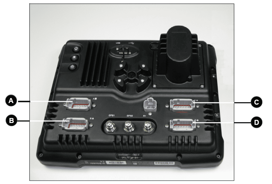
Connect the **T3H-G004** adapter to Port C or Port D on the FMX display depending on whether antenna port 1 or 2 is to be used. Port C will provide the NMEA output for antenna port 1 while Port D will provide NMEA output for antenna port 2.

[![image.png](https://docs.t3rra.com/uploads/images/gallery/2025-07/scaled-1680-/gv3g0LjujVC6TfsI-image.png)](https://docs.t3rra.com/uploads/images/gallery/2025-07/gv3g0LjujVC6TfsI-image.png)
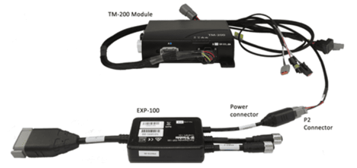
#### For GFX/TMX with TM-200 and EXP-100

Connect the T3H-G004 adapter to the EXP-100 port expander module.

[![image.png](https://docs.t3rra.com/uploads/images/gallery/2025-07/scaled-1680-/1femlJZ3ZAH8QE9L-image.png)](https://docs.t3rra.com/uploads/images/gallery/2025-07/1femlJZ3ZAH8QE9L-image.png)
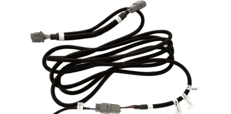
A port replicator is supplied in case the port was already in use for something else, if so disconnect the device, connect **T3H-G004** and then reconnect the device using the port replicator on **T3H-G004.**

[![image.png](https://docs.t3rra.com/uploads/images/gallery/2025-07/scaled-1680-/xxawJnUqq8xMDqhC-image.png)](https://docs.t3rra.com/uploads/images/gallery/2025-07/xxawJnUqq8xMDqhC-image.png)
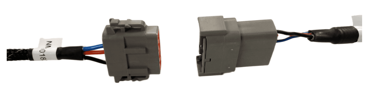
Connect the other end of **T3H-G004** to the **T3H-C002** ECU breakout harness.

[![image.png](https://docs.t3rra.com/uploads/images/gallery/2025-07/scaled-1680-/csTqSFz0mjgZA4Hw-image.png)](https://docs.t3rra.com/uploads/images/gallery/2025-07/csTqSFz0mjgZA4Hw-image.png)
Next, follow the setup process below for activating the NMEA output port on the FMX/TMX system.

## Activating the NMEA Output - FMX/FM1000

Make sure that if present, Autopilot is configured for use on Port A - this leaves Port C and Port D free for NMEA output of either implement receiver.

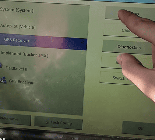
1\. Select the GPS Receiver listed below Autopilot \[Vehicle\] and press "Setup".

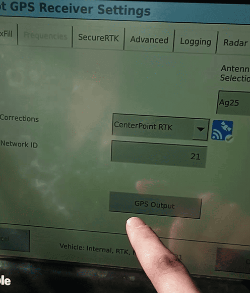
2\. Press the "GPS Output" button.

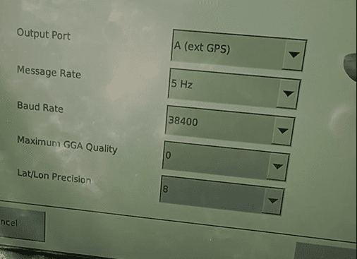
3\. Configure the NMEA GPS Output port as below:

- Select Output Port A (ext. GPS)
- Select a message rate of 5 Hz
- Select a Baud Rate of 38400
- Set Maximum GGA Quality to 0
- Set Lat/Lon Precision to 8
- Press the "NMEA Messages" Tab.

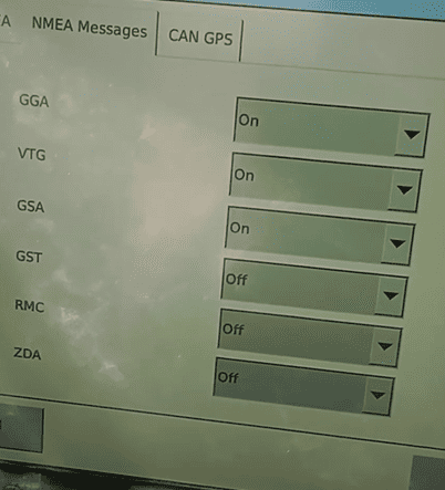
4\. Configure the NMEA Messages as below:

- Set GGA, to "On".
- Set GSA, to "On".
- Set VTG, to "On".
- Leave all other messages set to "Off".

[![image.png](https://docs.t3rra.com/uploads/images/gallery/2025-07/scaled-1680-/1eCDkWpS6dI6xoug-image.png)](https://docs.t3rra.com/uploads/images/gallery/2025-07/1eCDkWpS6dI6xoug-image.png)
[![image.png](https://docs.t3rra.com/uploads/images/gallery/2025-07/scaled-1680-/Di4SgRz29gVvrUIJ-image.png)](https://docs.t3rra.com/uploads/images/gallery/2025-07/Di4SgRz29gVvrUIJ-image.png)
[![image.png](https://docs.t3rra.com/uploads/images/gallery/2025-07/scaled-1680-/IG2n3zXiNXJzWaCS-image.png)](https://docs.t3rra.com/uploads/images/gallery/2025-07/IG2n3zXiNXJzWaCS-image.png)
[![image.png](https://docs.t3rra.com/uploads/images/gallery/2025-07/scaled-1680-/puLZoHxvb9qXPnNH-image.png)](https://docs.t3rra.com/uploads/images/gallery/2025-07/puLZoHxvb9qXPnNH-image.png)
# 8.3 | Modern Case IH / New Holland / Trimble

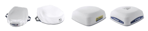
This section covers connection of Novatel-based GNSS receivers using a 12-pin Deutsch interface.

**Applicable to receivers including:** Case IH - Vector Pro  
New Holland - PLM Cygnus  
Trimble - AG-372, AG-392, NAV-900  
Steyr - S-Guide

[![image.png](https://docs.t3rra.com/uploads/images/gallery/2026-07/scaled-1680-/NYR6G2QZm2Kn3gr7-image.png)](https://docs.t3rra.com/uploads/images/gallery/2026-07/NYR6G2QZm2Kn3gr7-image.png)
## Parts Required

- **<span data-sheets-root="1">BPF11284 - </span>**<span data-sheets-root="1">Front Extension Harness (10m)</span>
- **<span data-sheets-root="1">PF81137 - </span>**<span data-sheets-root="1">Implement Pigtail Terminator Wiring Harness</span>
- **T3H-G002** - COMMAND Impl Adapter - NAV-900
- **T3H-S001** - COMMAND Impl Adapter – Stub Junction
- **Optional - T3H-G001 / T3H-G007** - COMMAND NMEA Extension Harness 
    - Only required if using NMEA 0183 Serial for GNSS data.

## Connection Process

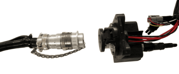
1\. Connect the John Deere Front Extension Harness to the ISOBUS breakaway connection.

2\. Route along the implement, allowing slack at pivot points and avoiding snag hazards.

[![image.png](https://docs.t3rra.com/uploads/images/gallery/2025-07/scaled-1680-/AsF8TBsTh5FtRUiE-image.png)](https://docs.t3rra.com/uploads/images/gallery/2025-07/AsF8TBsTh5FtRUiE-image.png)
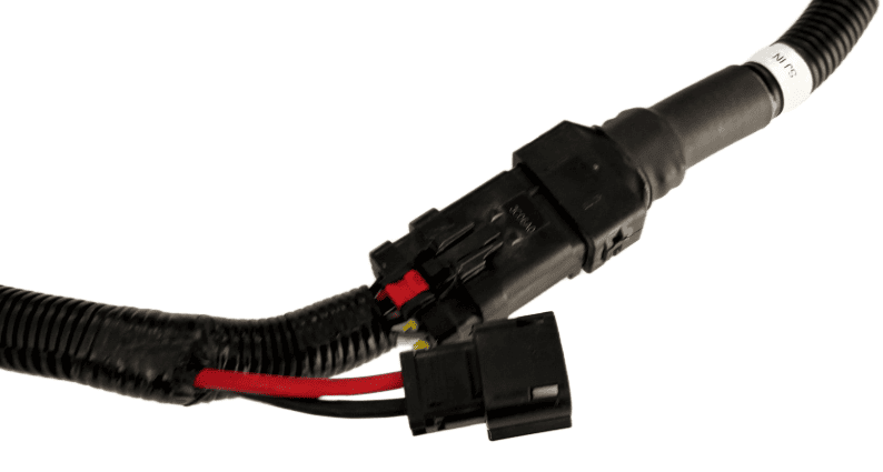
3\. Connect the **T3H-S001** adapter to the Front Extension Harness.

[![image.png](https://docs.t3rra.com/uploads/images/gallery/2025-07/scaled-1680-/SuU4oxt2DKiArihK-image.png)**![](https://lh7-rt.googleusercontent.com/slidesz/AGV_vUfb18F8k_oebTBPqwfo9XiNBZNwKnM3oAVQCWqCnu81_ej-90MsO88UGKN3PqpReGufqT-IkPoI1yc2PhvecRKLpNyTiBilDY77gJACZvIxS1F6s2OWMRFvOABjb9rzPqRAgXX6yw=s2048?key=pKn9UTVcy7kVo7f76IQZkQ "IMG_20250704_083710604_HDR.jpg")**](https://docs.t3rra.com/uploads/images/gallery/2025-07/SuU4oxt2DKiArihK-image.png)
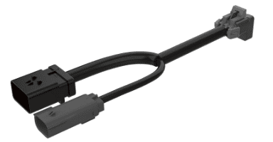
4\. Connect the Implement Pigtail Terminator to the **T3H-S001** adapter and secure the terminator to the implement receiver wiring harness.

[![image.png](https://docs.t3rra.com/uploads/images/gallery/2025-07/scaled-1680-/xGDljli6p8S80NtF-image.png)](https://docs.t3rra.com/uploads/images/gallery/2025-07/xGDljli6p8S80NtF-image.png)
5\. Connect the **T3H-G002** adapter to the **T3H-S001** adapter.

[![image.png](https://docs.t3rra.com/uploads/images/gallery/2025-07/scaled-1680-/JKqGyH4UW8wofgXl-image.png)](https://docs.t3rra.com/uploads/images/gallery/2025-07/JKqGyH4UW8wofgXl-image.png)
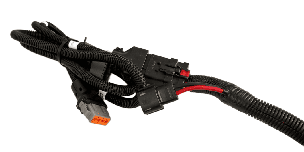
6\. Connect the **T3H-G002** adapter to the appropriate GNSS receiver port.

7\. If using NMEA 0183 Serial, also connect the NMEA extension harness to the **T3H-G002**, then connect the other end to the **T3H-C002** ECU breakout harness.

**Verify:**  
\- Receiver powers on

# 8.5 | NMEA 0183

NMEA 0183 Serial (RS232) capable receivers can be connected to the **COMMAND** system.

<p class="callout warning">**IMPORTANT:** If the GNSS receiver does not provide terrain compensation, an IMU must be installed to maintain accuracy.</p>

## Parts Required

- **<span data-sheets-root="1">BPF11284 - </span>**<span data-sheets-root="1">Front Extension Harness (10m)</span>
- **<span data-sheets-root="1">PF81137 - </span>**<span data-sheets-root="1">Implement Pigtail Terminator Wiring Harness</span>
- **T3H-S001** - COMMAND Impl Adapter – Stub Junction
- **T3H-G001 / T3H-G007** - COMMAND NMEA Extension Harness (8m or 12m)
- **Custom GNSS Adapter** - Custom adapter for connection of the NMEA 0183 Serial compatible receiver to the **T3H-S001** and **T3H-G001/G007** adapters.

## Connection Process


1\. Connect the John Deere Front Extension Harness to the ISOBUS breakway connector.

2\. Route along the implement, allowing slack at pivot points and avoiding snag hazards.

**![image.png](https://docs.t3rra.com/uploads/images/gallery/2025-07/scaled-1680-/VMiw0b4MueoRx1Ti-image.png)**3. Connect the **T3H-S001** adapter to the Front Extension Harness.
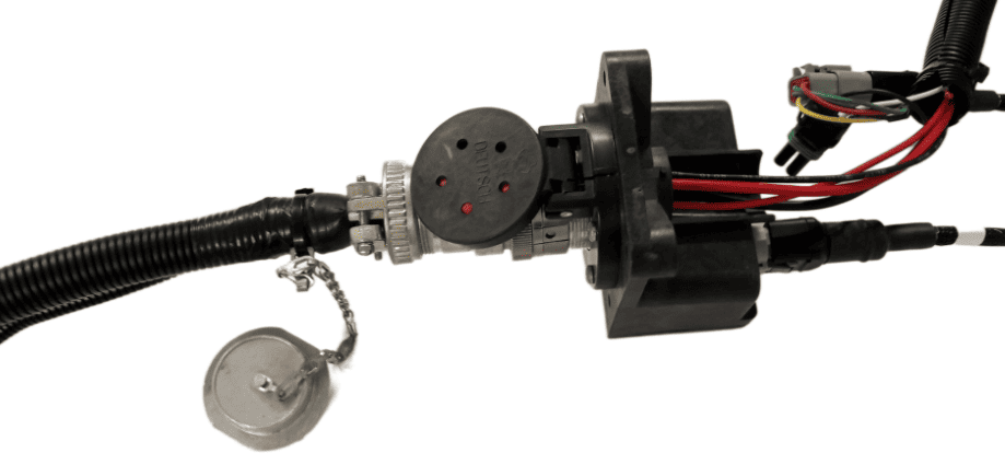
**[![image.png](https://docs.t3rra.com/uploads/images/gallery/2025-07/scaled-1680-/szCk65qzjfDIekAM-image.png)](https://docs.t3rra.com/uploads/images/gallery/2025-07/szCk65qzjfDIekAM-image.png)**
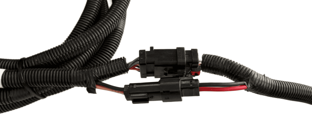
3\. Connect the **PF81137** Implement Pigtail Terminator to the Implement Receiver Wiring Harness and secure the terminator to the implement receiver wiring harness.

[![image.png](https://docs.t3rra.com/uploads/images/gallery/2025-07/scaled-1680-/xGDljli6p8S80NtF-image.png)](https://docs.t3rra.com/uploads/images/gallery/2025-07/xGDljli6p8S80NtF-image.png)

4\. Connect the **CUSTOM** adapter to the **T3H-S001** adapter.

5\. Connect the **CUSTOM**  adapter to the receiver's port ensuring connector keys are lined up.

6\. Connect the NMEA extension harness **T3H-G001** or **T3H-G007** to the **CUSTOM adapter, then connect the other end to the **T3H-C005** external breakout harness.

## Receiver Configuration

Perform necessary setup of the GNSS receiver using provided manufacturer tools or programs:

- - Talker ID should be set to GP or GN
    - Messages enabled - GGA, GSA, VTG
    - Output Update rate - 10Hz recommended
    - Baud Rate - 38400

**Verify:**  
\- Receiver powers on