8 | Receiver Connection and Configuration (GNSS)
Connecting various GNSS receivers for operation with COMMAND
- 8.1 | Modern NMEA 2000 (Case, New Holland, Trimble)
- 8.2 | Trimble FMX/GFX/TMX with Ag25
- 8.3 | NMEA 0183 (RS232)
- 8.4 | John Deere StarFire
8.1 | Modern NMEA 2000 (Case, New Holland, Trimble)
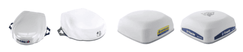
This section covers connection of Novatel-based GNSS receivers using a 12-pin Deutsch interface.
Applicable to receivers including:
Case IH - Vector Pro
New Holland - PLM Cygnus
Trimble / PTx Trimble - AG-372, AG-392, NAV-900, NAV-960
Steyr - S-Guide
Parts Required
- CNH 115-7100-009/10 - Front Extension Harness or JD BPF11284 - Front Extension Harness
- CNH 115-7100-005 - Cable Adapter Terminator Gen I ISOBUS or JD PF81137 - Implement Pigtail Terminator Wiring Harness
- T3H-G002 - COMMAND Impl Adapter - NAV-900
- T3H-S001 - COMMAND Impl Adapter – Stub Junction
Connection Process
1. Connect the Front Extension Harness to the ISOBUS breakaway connection.
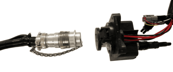
2. Route along the implement, allowing slack at pivot points and avoiding snag hazards.
3. Connect the T3H-S001 adapter to the Front Extension Harness.
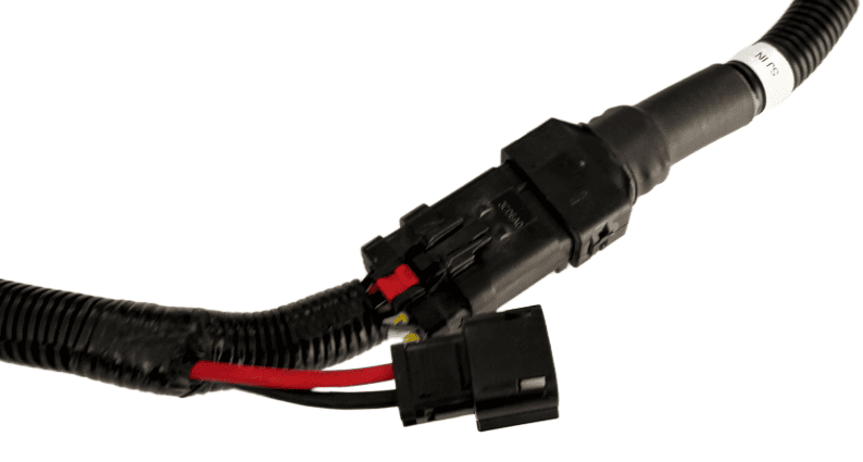
4. Connect the Implement Pigtail Terminator to the T3H-S001 adapter and secure the terminator to the implement receiver wiring harness.
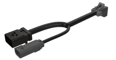
5. Connect the T3H-G002 adapter to the T3H-S001 adapter.
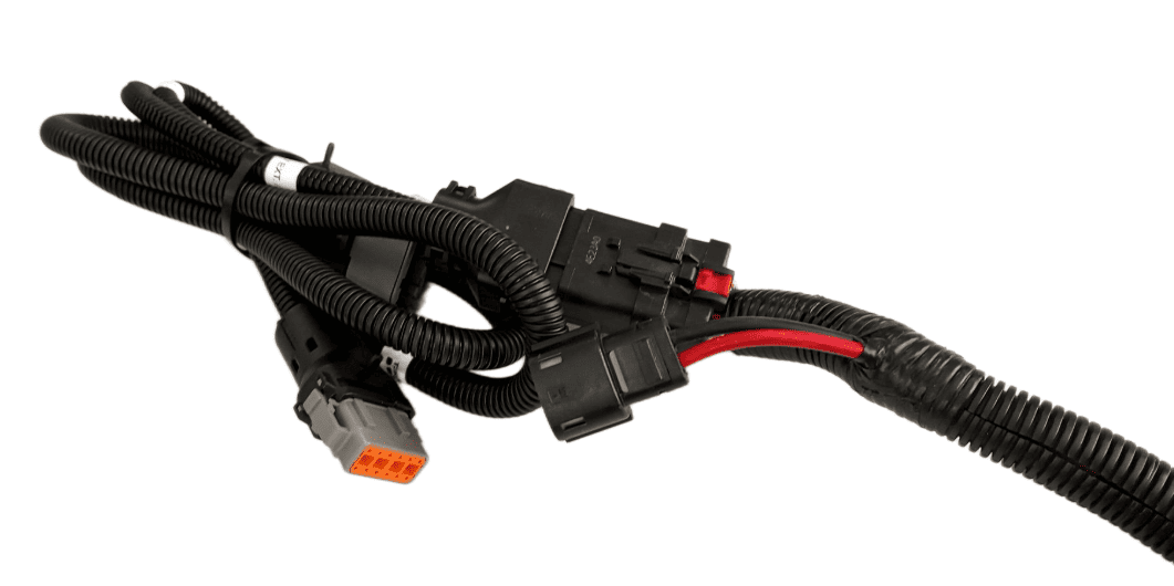
6. Connect the T3H-G002 adapter to the appropriate GNSS receiver port.
7. If using NMEA 0183 Serial, also connect the NMEA extension harness to the T3H-G002, then connect the other end to the T3H-C002 ECU breakout harness.
Verify:
- Receiver powers on
8.2 | Trimble FMX/GFX/TMX with Ag25
Applicable to:
Trimble FMX, GFX, and TMX displays using NMEA 0183 RS232 output via 12-way DTM port.
Harnessing Layout Overview
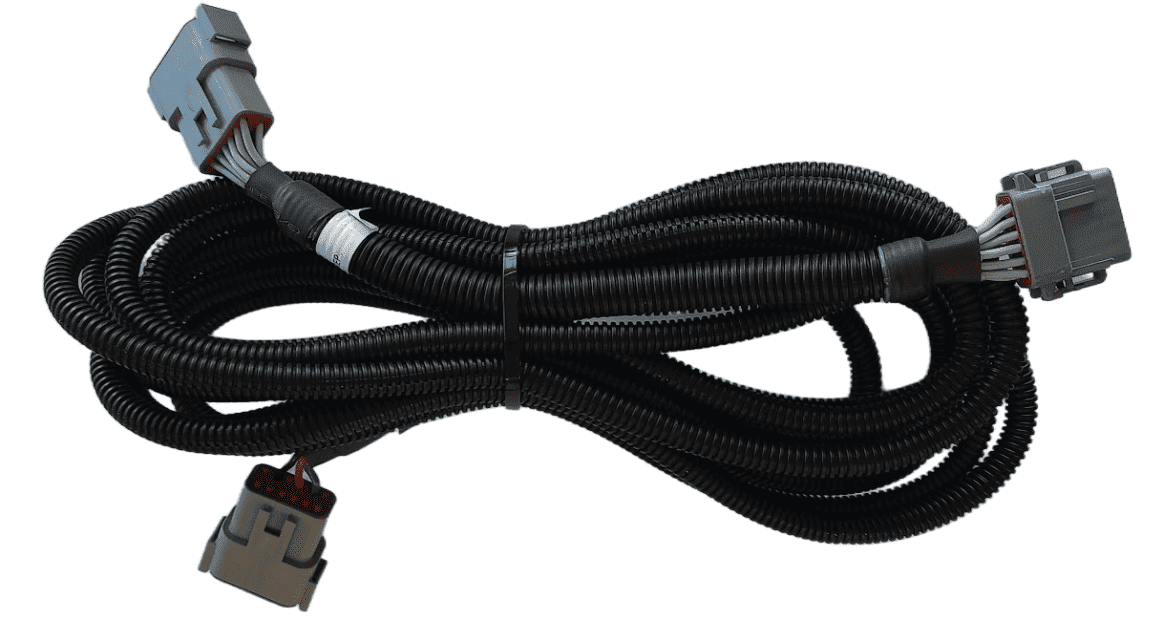
Usage of the FMX/TMX NMEA 0183 output only requires the addition of a T3H-G004 adapter to the T3H-C002 ECU breakout harness.
Parts Required
- T3H-G004 - COMMAND Trimble NMEA Output Adapter
Connection Process
NOTE: The T3H-G004 adapter routes the RS232 Tx and Rx connection to the COMMAND ECU and they are NOT replicated on the port replicator connector. All other pins are replicated for connection of other devices.
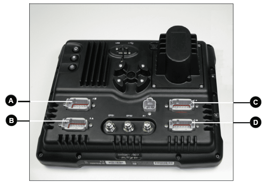
For FMX/FM1000
Connect the T3H-G004 adapter to Port C or Port D on the FMX display depending on whether antenna port 1 or 2 is to be used. Port C will provide the NMEA output for antenna port 1 while Port D will provide NMEA output for antenna port 2.
For GFX/TMX with TM-200 and EXP-100
Connect the T3H-G004 adapter to the EXP-100 port expander module.
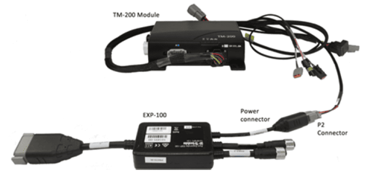
A port replicator is supplied in case the port was already in use for something else, if so disconnect the device, connect T3H-G004 and then reconnect the device using the port replicator on T3H-G004.
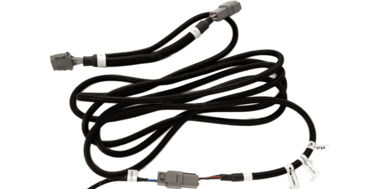
Connect the other end of T3H-G004 to the T3H-C002 ECU breakout harness.
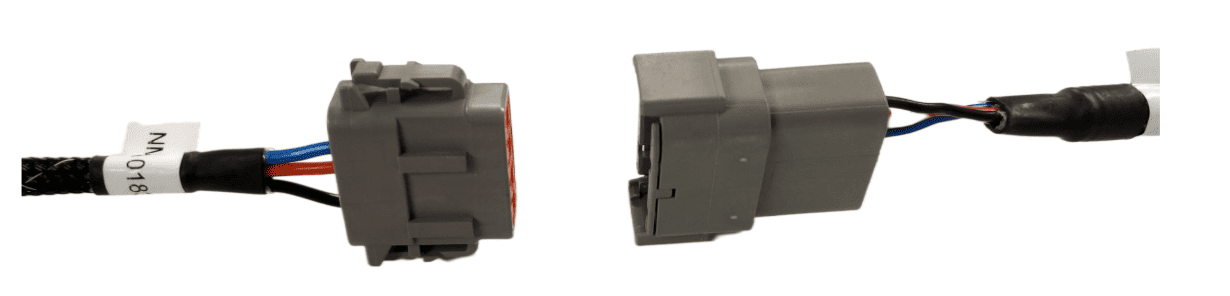
Next, follow the setup process below for activating the NMEA output port on the FMX/TMX system.
Activating the NMEA Output - FMX/FM1000
Make sure that if present, Autopilot is configured for use on Port A - this leaves Port C and Port D free for NMEA output of either implement receiver.
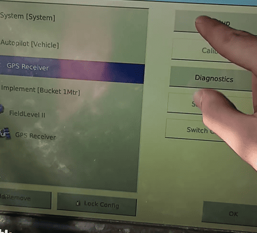
1. Select the GPS Receiver listed below Autopilot [Vehicle] and press "Setup".
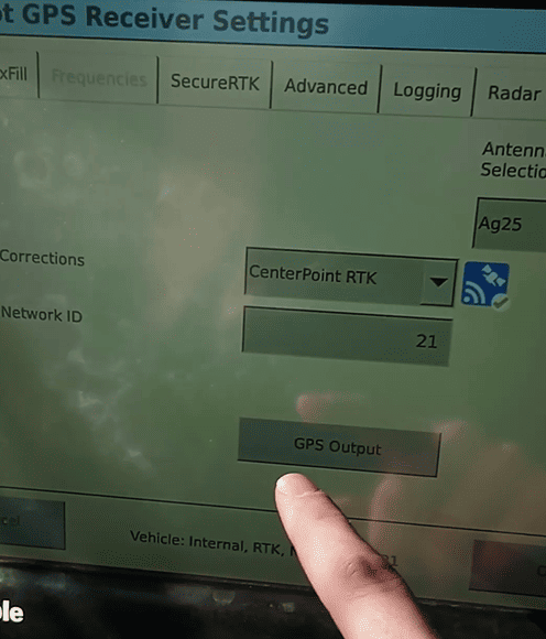
2. Press the "GPS Output" button.
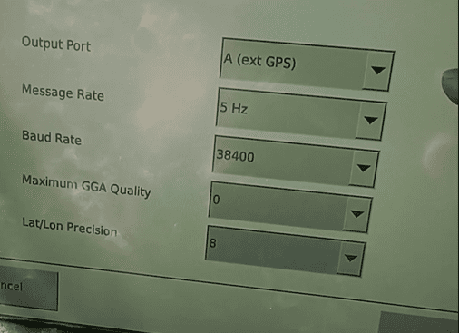
3. Configure the NMEA GPS Output port as below:
- Select Output Port A (ext. GPS)
- Select a message rate of 5 Hz
- Select a Baud Rate of 38400
- Set Maximum GGA Quality to 0
- Set Lat/Lon Precision to 8
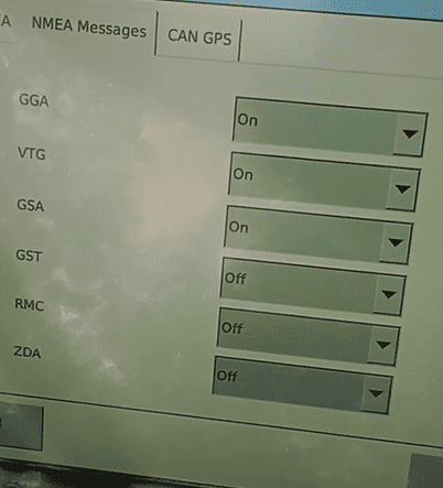
- Press the "NMEA Messages" Tab.
4. Configure the NMEA Messages as below:
- Set GGA, to "On".
- Set GSA, to "On".
- Set VTG, to "On".
- Leave all other messages set to "Off".
8.3 | NMEA 0183 (RS232)
NMEA 0183 Serial (RS232) capable receivers can be connected to the COMMAND system.
IMPORTANT: If the GNSS receiver does not provide terrain compensation, an IMU must be installed to maintain accuracy.
Parts Required
- CNH 115-7100-009/10 - Front Extension Harness or JD BPF11284 - Front Extension Harness
- CNH 115-7100-005 - Cable Adapter Terminator Gen I ISOBUS or JD PF81137 - Implement Pigtail Terminator Wiring Harness
- T3H-S001 - COMMAND Impl Adapter – Stub Junction
- T3H-G001 / T3H-G007 - COMMAND NMEA Extension Harness (8m or 12m)
- Custom GNSS Adapter - Custom adapter for connection of the NMEA 0183 Serial compatible receiver to the T3H-S001 and T3H-G001/G007 adapters.
Connection Process
1. Connect the Front Extension Harness to the ISOBUS breakway connector.
2. Route along the implement, allowing slack at pivot points and avoiding snag hazards.
 3. Connect the T3H-S001 adapter to the Front Extension Harness.
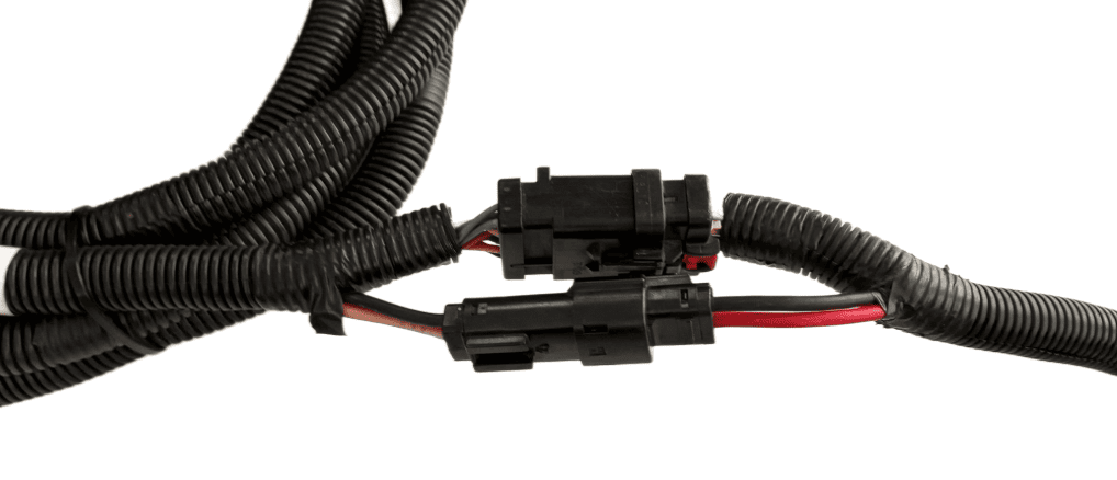
4. Connect the Implement Pigtail Terminator to the Implement Receiver Wiring Harness and secure the terminator to the implement receiver wiring harness.
5. Connect the CUSTOM adapter to the T3H-S001 adapter.
6. Connect the CUSTOM adapter to the receiver's port ensuring connector keys are lined up.
7. Connect the NMEA extension harness T3H-G001 or T3H-G007 to the CUSTOM adapter, then connect the other end to the T3H-C005 external breakout harness.
Receiver Configuration
Perform necessary setup of the GNSS receiver using provided manufacturer tools or programs:
-
- Talker ID should be set to GP or GN
- Messages enabled - GGA, GSA, VTG
- Output Update rate - 10Hz recommended
- Baud Rate - 38400
Verify:
- Receiver powers on
8.4 | John Deere StarFire
Applicable to:
John Deere StarFire 3000, 6000, 7000 & 7500 GNSS receivers using implement harnessing.
Harnessing Layout Overview
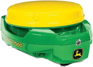
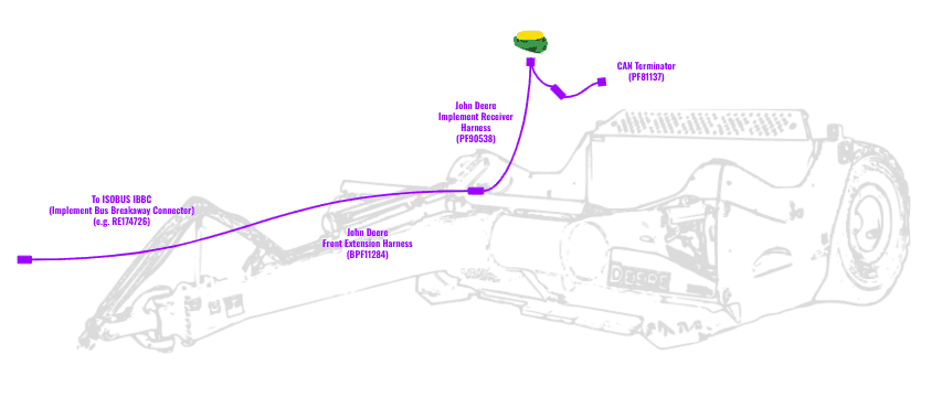
For use with COMMAND, the John Deere StarFire can be set up with typical John Deere implement harnessing:
- RE174726 - Greenstar ISOBUS IBBC (Implement Bus Breakaway Connector) if not present, IBBC from other manufacturers are also appropriate for COMMAND.
- BPF11117 - John Deere Front Extension Harness with Terminator (10m)
- OR BPF11284 - John Deere Front Extension Harness (10m)
- AND PF81137 - John Deere Implement Pigtail Terminator Wiring Harness
- PF90538 - John Deere Implement Receiver Wiring Harness Kit
Connection Process
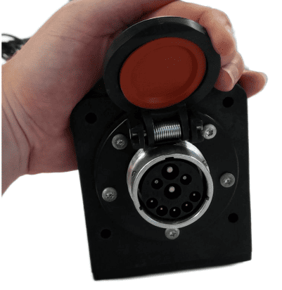
1. Connect the John Deere Front Extension Harness to the ISOBUS breakaway connection.
2. Route along the implement, allowing slack at pivot points and avoiding snag hazards.
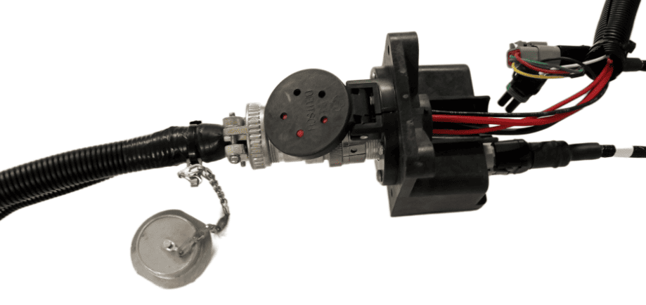
3. Connect the Implement Receiver Wiring Harness to the Front Extension Harness and route the cabling up toward the receiver mast.
4. Connect the Implement Receiver Wiring Harness to the Starfire receiver 12-pin DT connector. A 12-pin Deutsch gender change adapter may be needed to connect the DT06-12SA connector on the implement receiver harness to the DT06-12SA connector on the StarFire Receiver.
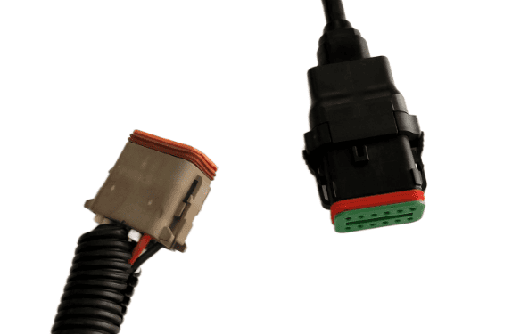
5. Connect the PF81137 Implement Pigtail Terminator to the Implement Receiver Wiring Harness and secure the terminator to the implement receiver wiring harness.
Verify:
- Receiver powers on