**IMPORTANT**: Moving the SCV lever will disengage AUTO mode in modern JD tractors, so movements based on any current valve signals will cease. Always keep this in mind during operation - the lever must be pushed into detent position again to resume automatic control.
For more information on configuring **COMMAND** for use with John Deere CAN SCVs, refer to the **Level COMMAND** Manual.
# 7.2 | John Deere Legacy (Analog) **Applicable to:** John Deere tractors with analog SCV control (typically pre-2005 models). [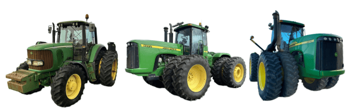](https://docs.t3rra.com/uploads/images/gallery/2025-07/2RFwr0u047bF0F0B-image.png) ## Connection Method **COMMAND** can control John Deere legacy valve systems through the use of a **T3H-V001** **COMMAND** Legacy Output Adapter. ## Installation Steps #### 10-way Metripack 150 Series Connection 1. Connect the **T3H-V001** adapter to the **T3H-C002** ECU breakout harness at the round Deutsch HD series connector. #### [](https://docs.t3rra.com/uploads/images/gallery/2025-07/CWrcAdy0xnqMfSop-image.png) 2\. Connect the 10-way Metripack connector on **T3H-V001** to the tractor's SCV signal input plug. ## John Deere SCV Controller Connection Overview [](https://docs.t3rra.com/uploads/images/gallery/2025-06/S1UiDBeLj4L7cY1d-image.png) [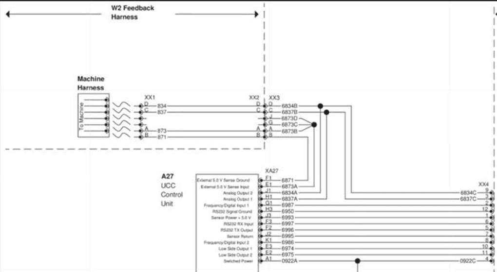](https://docs.t3rra.com/uploads/images/gallery/2025-06/v9gdrQPYeMUY0uyl-image.png) ## Operation Notes **COMMAND** interfaces with legacy John Deere tractor SCVs by sending analog voltage signals to the integrated valve controller, commanding either port A or port B flow of two of the rear tractor SCVs (generally SCV1 and SCV3). To operate the SCVs in automatic control mode, the user must push the respective SCV lever forward into the detent position. This will cause "AUTO" to appear on the console/display to indicate that the SCV is ready for automatic control commands. Moving the lever will disengage AUTO mode on the console/armrest. To re-enter AUTO mode, push the SCV lever into detent position again.**IMPORTANT**: Moving the SCV lever will disengage AUTO mode in modern JD tractors, so movements based on any current valve signals will cease. Always keep this in mind during operation - the lever must be pushed into detent position again to resume automatic control.
For more information on configuring **COMMAND** for use with JD Legacy Proportional SCVs, refer to the **Level COMMAND** Manual.
# 7.3 | CNH Direct Connect (AFS Connect / PLM Intelligence) **Applicable to:** Case IH / New Holland tractors with AFS Connect or PLM Intelligence systems. [](https://docs.t3rra.com/uploads/images/gallery/2025-07/HBhMQQ3eVQl7QHWG-image.png) ## Connection Method **[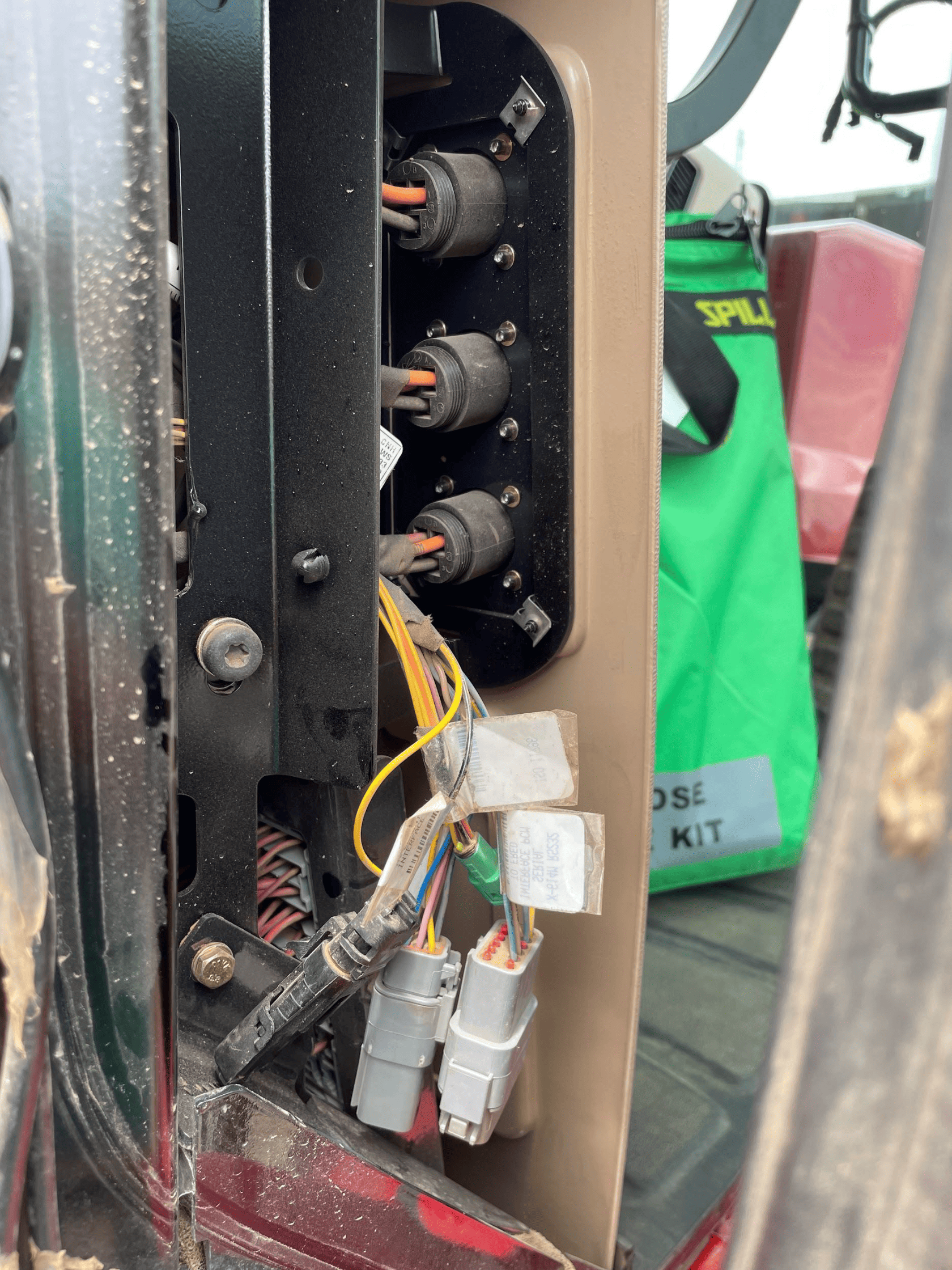](https://docs.t3rra.com/uploads/images/gallery/2025-06/R3uuiKBzm8bcb1Oq-image.png)COMMAND** can control Case & New Holland rear tractor valve (EHR) systems through the use of a **T3H-V001** **COMMAND** Legacy Output Adapter. ## Installation Steps The Case / New Holland tractor connection for analog control signal inputs via the **T3H-V001** adapter are generally found in one of three locations depending on tractor model: 1\. Locate the tractor SCV signal input connector: \- Fuse compartment \- Behind driver seat \- Under cab exterior (4WD models) 2\. Connect the **T3H-V001** adapter to the tractor connection. 3\. Connect the **T3H-V001** adapter to the **T3H-C002** harness. [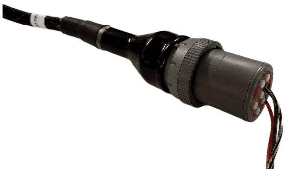](https://docs.t3rra.com/uploads/images/gallery/2025-07/ywPFWUQXnCahBXUF-image.png) ## Tractor Valve Configuration 1\. After completing the physical connection, the system must be configured on the tractor armrest display. [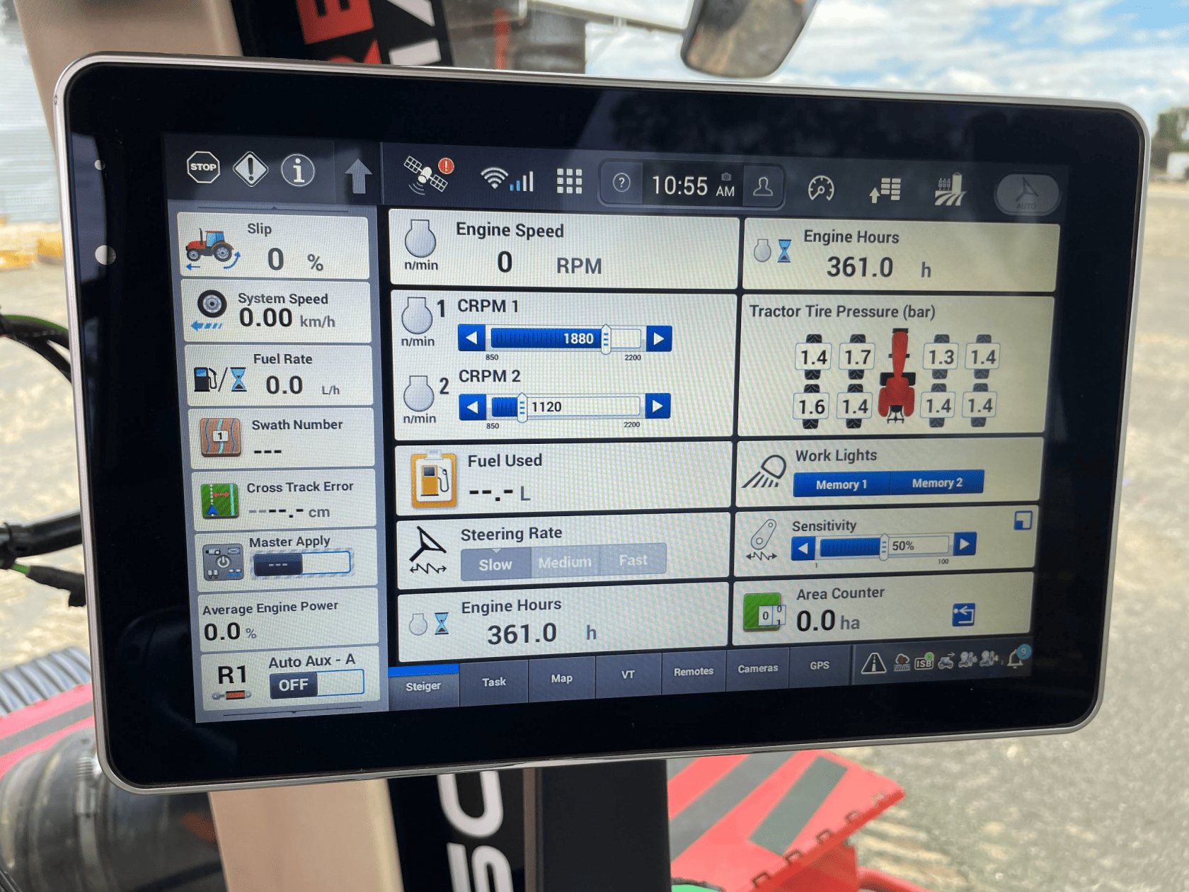](https://docs.t3rra.com/uploads/images/gallery/2025-06/6citV3azhXn8CjJm-image.png) 2\. Ensure that a new implement profile has been created for use with the scraper, or that the currently selected profile is appropriate. [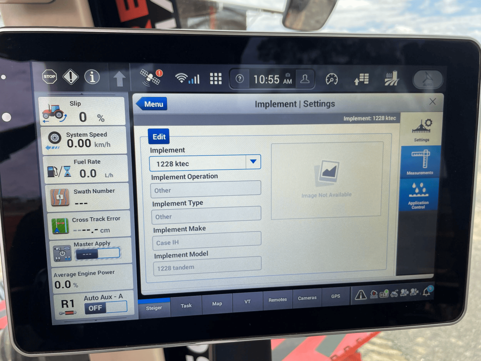](https://docs.t3rra.com/uploads/images/gallery/2025-06/KB1fxjEPXkB2epeJ-image.png) 3\. Open the “Remotes” settings tab to display remote valve configuration. [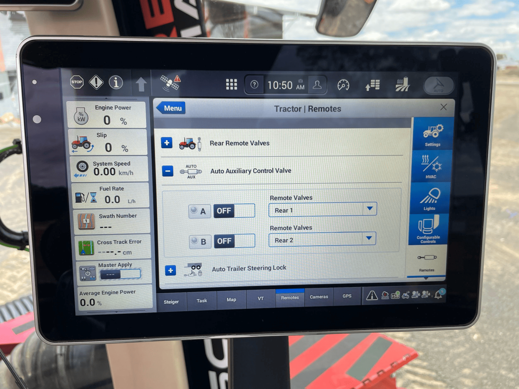](https://docs.t3rra.com/uploads/images/gallery/2025-06/4H2xNOyVIHbWMUJF-image.png) 4\. Set the desired remote valve outputs at the back of the tractor to the desired function (A or B). [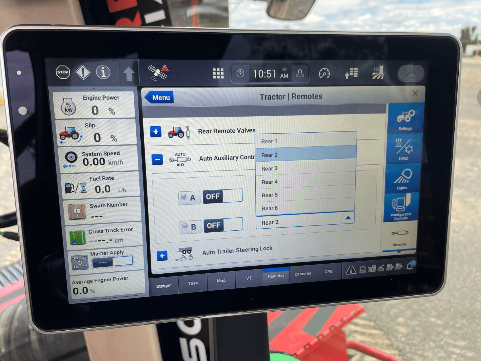](https://docs.t3rra.com/uploads/images/gallery/2025-06/m6PNSJkMFxWwK435-image.png) **NOTE**: The remote valves selected for A and B should be matched to the valve connections at the back of the tractor pictured below. We recommend setting auxiliary valve A to remote valve “Rear 1”, and setting auxiliary valve B to remote valve “Rear 2”, which will configure remote valves 1 and 2 at the back of the tractor for use with **COMMAND**. [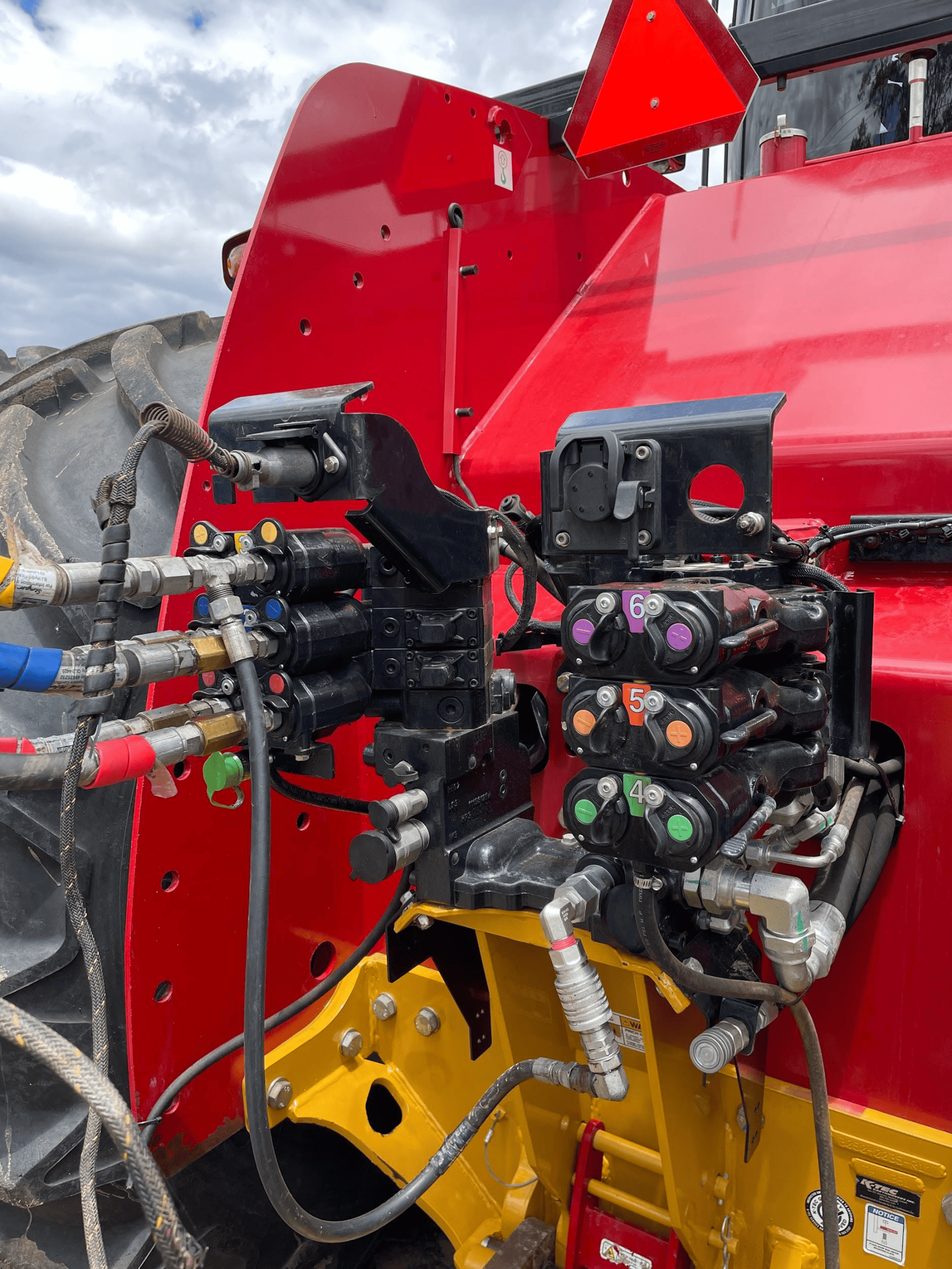](https://docs.t3rra.com/uploads/images/gallery/2025-06/uy2QGbE152OG4u48-image.png) 5\. Once the remote valves on the tractor have been set to the desired auxiliary function, the machine should now be fully configured and ready for use. In order to engage auxiliary control, the user must ensure that the Auto Auxiliary Control Valves A & B have been turned on in the relevant area on the “Remotes” page. 6\. The “Auto Auxiliary Control Valve” can be accessed either by the hydraulic cylinder shortcut next to the display navigation dial on the armrest, or by adding the menu to the display home page. Once this menu is accessed, turn either or both required function to the on position and briefly push the selected remote valve lever forward until it clicks, then release it. The lever returns to its resting position. [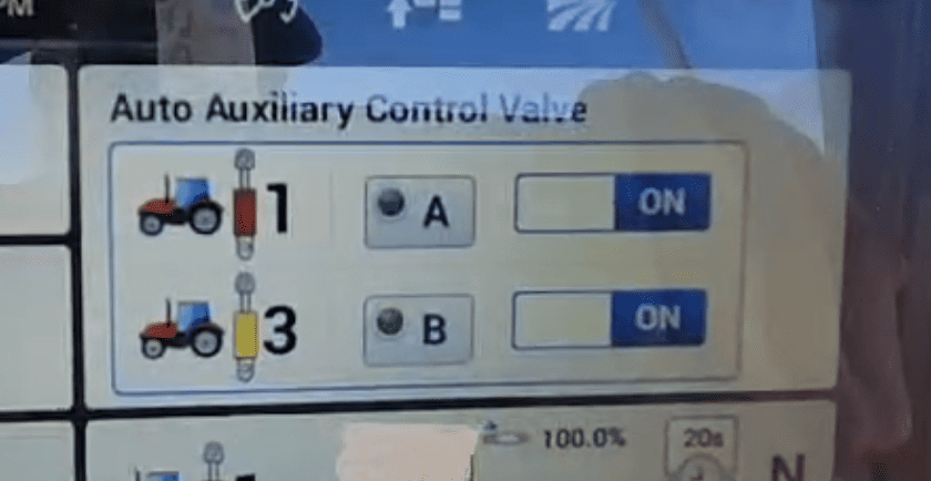](https://docs.t3rra.com/uploads/images/gallery/2025-06/IpXIImajv9x3G1CJ-image.png) ## Operation Notes **COMMAND** interfaces with the Case / New Holland tractor valves by sending analog signals to the integrated valve controller, commanding either port A or port B flow of two of the rear tractor SCVs (For AFS Connect models any SCV can be linked to either of the two analog inputs). To operate the SCVs in automatic control mode, the user first needs to arm one or both of the configured auto SCVs by toggling the Auto Auxiliary Control Valve toggles to ON. Then, either push the respective SCV lever forward into the detent position or press the respective SCV button in front of the levers. This will cause the A and/or B LEDs on the pro 1200 screen to change to solid green, indicating the valves are active for automatic control. Levers can be moved manually, which will override automatic control and once let go, automatic control will resume. To disable automatic control, pull or push the respective SCV lever until it clicks. The A or B LED on the pro 1200 screen should now begin flashing, meaning that automatic control is paused until the operator resumes by pushing the lever to detent or pressing the SCV button again.**IMPORTANT**: Moving the SCV lever alone will NOT disengage AUTO mode in modern case tractors, so movements based on any current valve signals will continue. Always keep this in mind during operation.
For more information on configuring **COMMAND** for use with Case / New Holland auxiliary rear valve control inputs, please refer to the **Level COMMAND** Manual.
# 7.4 | CNH Pre AFS Connect / PLM Intelligence **Applicable to:** Case IH / New Holland tractors prior to AFS Connect or PLM Intelligence systems. [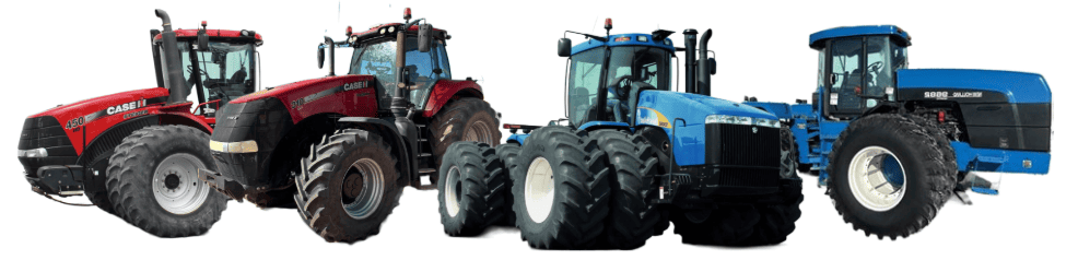](https://docs.t3rra.com/uploads/images/gallery/2025-07/3zce9clzBH4n9Ehs-image.png) ## Connection Method **[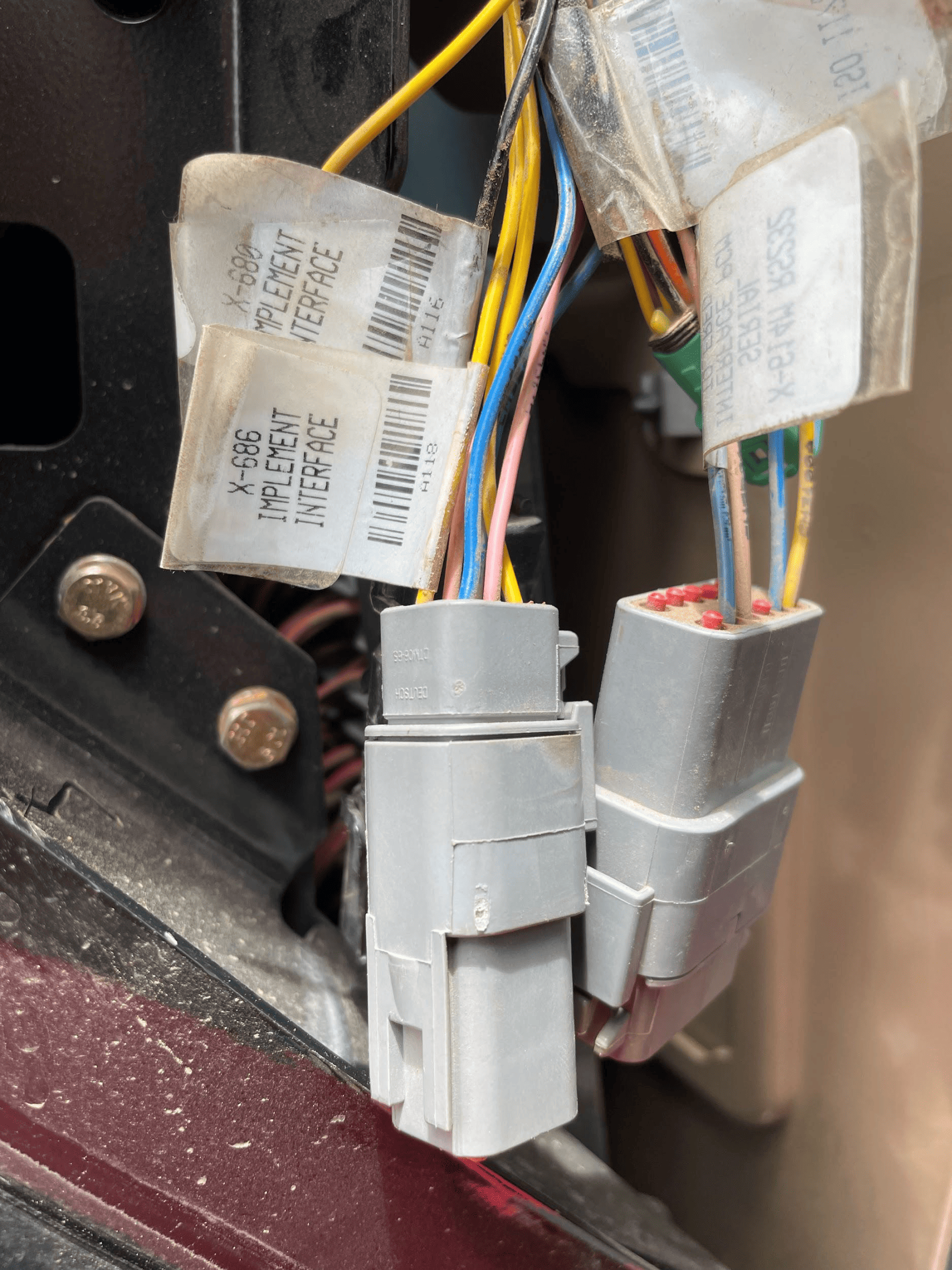](https://docs.t3rra.com/uploads/images/gallery/2025-06/UXcDtoEbWqZOG4bC-image.png)COMMAND** can control Case analog input (EHR) valve systems through the use of a **T3H-V001** COMMAND Legacy Output Adapter. ## Installation Steps The Case / New Holland tractor connection for analog control signal inputs via the **T3H-V001** adapter are generally found in one of three locations depending on tractor mode: 1\. Locate the tractor SCV signal input connector: \- Fuse compartment \- Behind driver seat \- Under cab exterior (4WD models) 2\. Connect the **T3H-V001** adapter to the tractor connection. 3\. Connect the **T3H-V001** adapter to the **T3H-C002** harness. [](https://docs.t3rra.com/uploads/images/gallery/2025-07/ywPFWUQXnCahBXUF-image.png) ## Tractor Valve Configuration Select the applicable configuration method: \- New-style instrument cluster \- Old-style instrument cluster \- Tier IV systems ### New-style Instrument Cluster #### Entering The Configuration Menu - Locate the corner post instrument cluster in the tractor cab (Pictured right). - Power up the tractor and press the PROG button on the instrument cluster until “CONFIG MENU” appears. - Press the “DECR” button until AUX/Hitch/PTO is highlighted and then press the “PROG” button. - Navigate to “EHR MENU” using the up and down arrow buttons and press the “PROG” button. #### Setting Auxiliary Mode - Use the Up/Down arrow buttons to find “AUX VIEW” and then press the “PROG” button. - Use the Up/Down arrow buttons until “SCRPR OPTION” appears and then press the “PROG” button. - Depending on the implement being used, select the correct option using the Up/Down arrow buttons and then press the “PROG” button. - For single implement height control only - “1 LASER” - For dual implement height control - “2 LASER” - For single implement height & cross-slope control - “2 LASER” #### Exiting The Configuration Menu - Press the Up/Down arrow buttons until “AUX EXIT” is shown and then press the “PROG” button. - Press the Up/Down arrow buttons until “EXIT TMF MENU” is shown and then press the “PROG” button. - Press the Up/Down arrow buttons until “EXIT” is shown and then press the “PROG” button. #### Auto/Manual System Operation - The tractor will require an Auxiliary (1-3) switch, which is used to toggle between automatic and manual operation for the two auxiliary inputs. - To toggle between Automatic and Manual operation for either SCV1 or SCV3, press the relevant side of the auxiliary (1-3) switch. [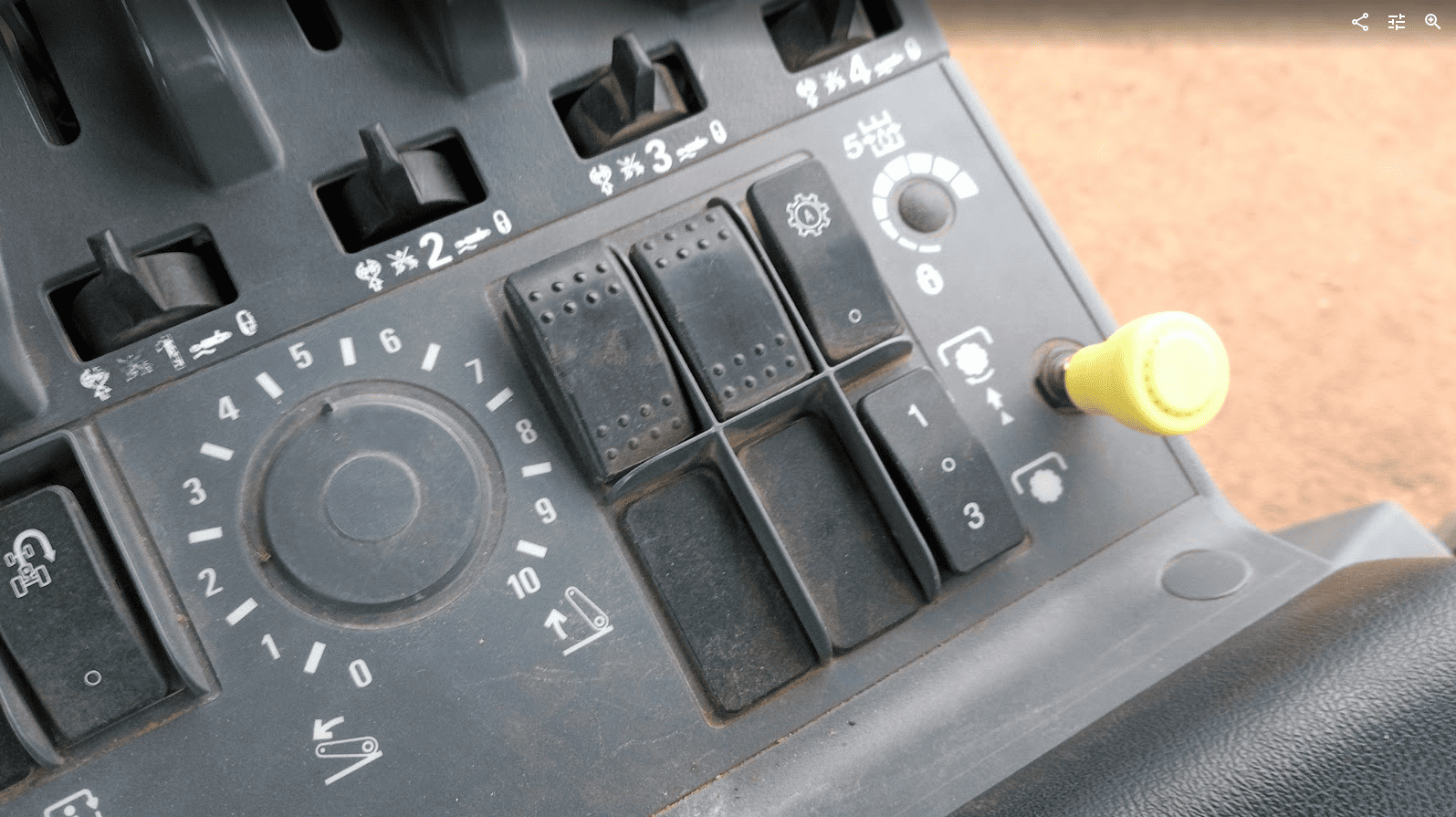](https://docs.t3rra.com/uploads/images/gallery/2025-07/dJF8eLdCINg0NC7q-image.png) ### Old-style Instrument Cluster #### Enabling Auxiliary/Remote Valve Control - Turn on the tractor key switch and within 10 seconds, press and hold the “PROG” button on the instrument cluster for 3 seconds - “INST SET MENU” should appear. - Press the “INCR” or “DECR” buttons until “AUX SET MENU” is displayed, then press the “PROG” button. - Press the “INCR” or “DECR” buttons until “AUX SETUP” is displayed, then press the “PROG” button. - Press the “INCR” or “DECR” buttons to set the required number of “scrapers” between NONE, 1 and 2. In this situation a “scraper” can be considered equivalent to an SCV. - For single implement height control - select 1 SCRAPER - For dual implement height control - select 2 SCRAPER - For single implement height & cross-slope control - select 2 SCRAPER - Press the “PROG” button to accept the number of scrapers on the display. #### Exiting The Configuration Menu - Press the “INCR” or “DECR” buttons until “AUX EXIT” is displayed, then press the “PROG” button. - Press the “INCR” or “DECR” buttons until “EXIT SET MENU” is displayed, then press the “PROG” button. - To complete the calibration process, use the key to turn the ignition off. ### CNH Tier IV #### Enabling Auxiliary/Remote Valve Control - Turn on the tractor ignition key switch and within 10 seconds, press and hold the “ENTER” button on the keypad to enter the Config Menu. - Press the Up or Down arrow keys until “TCU” is displayed and then press “ENTER”. - Press the Up or Down arrow keys until “EHR MENU” appears and then press “ENTER”. - Press the Up or Down arrow keys until “EHR SETUP” is displayed and then press “ENTER”. - “SCRPR NONE” will likely be displayed on the screen. Press the Up or Down arrow button until either “SCRPR 1 LASER” or “SCRPR 2 LASER” is displayed depending on the user’s application and then press “ENTER”. - For single implement height control only - select 1 LASER - For dual implement height control - select 2 LASER - For single implement height & cross-slope control - select 2 LASER - The user can now navigate out of the setup screens or turn the key off - the selected setting will be saved. #### Auto-Auxiliary Mode Operation - The user can toggle between Automatic and Manual operation of the auxiliary outputs using the “1” and “3” buttons on the console. - The LED on the relevant button will be illuminated when in Automatic operation mode. - During operation in automatic mode, the upper portion of the programmable display will show the auto state of the auxiliary outputs. - Automatic control can be temporarily overridden by the operator using the remote hydraulic lever, which will cause the indicator LED on the “1” or “3” console button to flash. ## Operation Notes **COMMAND** interfaces with the CNH external remotes/valves by sending analog signals to the integrated valve controller, commanding either port A or port B flow of two of the rear tractor SCVs (For AFS Connect models any SCV can be linked to either of the two inputs, whereas older models are limited to SCV1 and SCV3). To operate the SCVs in automatic control mode, the user first needs to arm one or both of the configured auto SCVs using the 1/3 switch, display or buttons on the armrest .**IMPORTANT**: Moving the SCV lever alone will NOT disengage AUTO mode in modern case tractors, so movements based on any current valve signals will continue. Always keep this in mind during operation.
For more information on configuring **COMMAND** for use with Pre AFS Connect / PLM Intelligence SCVs, refer to the **Level COMMAND** Manual.
# 7.5 | Versatile — Analog Scraper Control **Applicable to:** Supported Versatile L4WD and DeltaTrack tractors fitted with the 6-pin **C920** laser/scraper control interface connected to the tractor Gateway Control Module (GCM).**NOTE:** MFWD models may use a different interface arrangement. The 400 HP R3T3 MFWD documentation specifies separate installation instructions; the connection and setup procedure below has not been verified for that arrangement.
[](https://docs.t3rra.com/uploads/images/gallery/2026-09/Dhkimage.png) ## Connection Method **COMMAND** controls the tractor’s rear electrohydraulic remote valves through the **T3H-V001** analog output adapter and the tractor’s 6-pin scraper interface connection. The tractor interface provides control of two remote valves: - **Input 1:** Remote valve 1 - **Input 2:** Remote valve 3 ## Installation Steps 1\. Complete the machine preparation steps in Section 5.1 and isolate the tractor electrical supply. 2\. Remove the electrical compartment cover at the rear of the cab, behind the operator’s seat. 3\. Locate the 6-pin scraper interface connector near the Gateway Control Module. In the Versatile installation documentation, this connector is identified as **C920**. [](https://docs.t3rra.com/uploads/images/gallery/2026-09/GAGimage.png) 4\. Connect the tractor-side 6-pin connection of the **T3H-V001** adapter arrangement to the scraper interface. 5\. Connect the **T3H-V001** adapter to the valve output connection on the **T3H-C002** ECU breakout harness. [](https://docs.t3rra.com/uploads/images/gallery/2026-09/PmSimage.png) 6\. Secure the harness clear of moving parts and sharp edges, refit the compartment cover and restore the electrical supply.**NOTE:** If the scraper interface is not fitted, the appropriate tractor interface harness must be installed first. Versatile specifies interface kit **86053584** for the models covered by installation instructions **89004246**. The documented 400 HP R3T3 MFWD arrangement uses kit **86094592**, with installation instructions **89007622**. Have the Versatile dealer confirm the correct kit for the tractor model and serial number and follow the corresponding installation instructions.
## Tractor Valve Configuration The tractor’s scraper control interface is disabled by default and must be enabled through the Electronic Instrument Cluster. 1\. Keep **COMMAND** disarmed and turn on the tractor ignition. 2\. Use the display **Up/Down** buttons to navigate to **CALIBRATION**. 3\. Press **OK (SELECT)** until **Scraper Control** is displayed. [](https://docs.t3rra.com/uploads/images/gallery/2026-09/gxMimage.png) 4\. Press **Show subscreen**. 5\. Press **OK** to change the setting from **OFF** to **ON**. [](https://docs.t3rra.com/uploads/images/gallery/2026-09/Xncimage.png) 6\. Press **EXIT** to complete the setup. 7\. On the EHR monitor, select **Manual Operation** for remote valves **1 and 3**, and leave both hydraulic control levers in **neutral**.**IMPORTANT:** Do not select **Continuous** mode for remote valves 1 and 3 when using the scraper control interface.
**NOTE:** Compatible tractor software is required. Versatile instructions **89004246** specify gateway software **D2T411 or later** for the covered Tier 4i models, **D2T311 or later** for the covered Tier 3 models, and dash software **EICD214**. Software requirements for other models must be confirmed with the Versatile dealer. If the **Scraper Control** option is unavailable, have the dealer verify the tractor’s software and interface configuration.
[](https://docs.t3rra.com/uploads/images/gallery/2026-09/vnaimage.png) ## Operation Notes Once Scraper Control is enabled and the remotes are configured as above, the tractor accepts external control signals while the remote levers are in neutral. No lever detent action is required to activate the interface. Use the **COMMAND Arm/Engage switch** to arm the system and engage automatic control. The remote levers can temporarily override automatic hydraulic control. Returning a lever to neutral allows the tractor to respond to **COMMAND** again if automatic control remains engaged.**IMPORTANT:** Moving a tractor remote lever does not disengage **COMMAND** automatic control. To stop automatic control, disengage it directly using the **COMMAND Arm/Engage switch**. Disengage by pressing the momentary side or move the switch to **OFF** to disarm **COMMAND** and disable its hydraulic control outputs.
For configuration of the analog valve interface and valve calibration, refer to the **Level COMMAND Manual**. # 7.6 | External Proportional Solenoid Valves — Direct PWM Coil Drive **Applicable to:** External proportional valves with solenoid coils driven directly by COMMAND’s PWM outputs. For valves fitted with Danfoss PVE electronic actuators, refer to the Danfoss PVE installation section.**IMPORTANT:** Confirm that the external valve’s electrical requirements are compatible with **COMMAND**. The ECU supports a maximum coil current of **2 A**. If a coil would draw more than 2 A at full output (100% PWM), reduce the corresponding **Max %** setting in **Level COMMAND** before operating the valve. This limits the maximum output to prevent an overcurrent fault.
## Connection Method **COMMAND** directly controls the valve solenoids using current-controlled PWM outputs. The **T3H-V002** valve extension connects to the **T3H-C002** ECU breakout harness and provides a 6 m extension to the implement-mounted valves. The **T3H-V003 — Valve Adapter – Prop. Solenoid (2-way DT)** connects the extension to valves fitted with compatible 2-pin Deutsch connections.**NOTE:** For valves using other connector types, such as Hirschmann, the dealer or installer must provide a suitable adapter. T3RRA currently supplies the 2-pin Deutsch valve adapter only. Any alternative adapter must maintain the correct circuit connections and comply with the valve manufacturer’s polarity requirements.
## Installation Steps 1\. Complete the machine preparation steps in **Section 5.1** and isolate the tractor electrical supply. 2\. Connect the **T3H-V002** valve extension to the valve output connector on the **T3H-C002** ECU breakout harness. [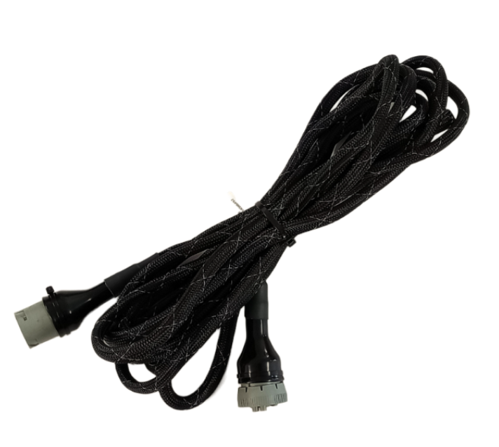](https://docs.t3rra.com/uploads/images/gallery/2026-09/e7oimage.png) 3\. Route the extension to the external valve block. Allow sufficient slack for tractor articulation and implement movement, and secure the harness clear of moving parts, hot surfaces and pinch points. 4\. Connect the **T3H-V003** valve adapter, or suitable alternative adapter, to the implement end of the **T3H-V002** extension. [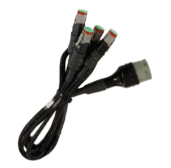](https://docs.t3rra.com/uploads/images/gallery/2026-09/d1Cimage.png) 5\. Connect the adapter’s solenoid plugs to the appropriate valve coils for each controlled function, such as height and cross-slope. Identify the raise/lower or tilt directions for verification during setup. 6\. Secure the connections and protect any unused connectors against moisture and dirt. 7\. Keep **COMMAND** disarmed and restore the electrical supply. ## Valve Configuration Confirm that the valve’s electrical requirements are compatible with **COMMAND** before operating the outputs. Refer to **Section 2.4** for proportional solenoid compatibility. [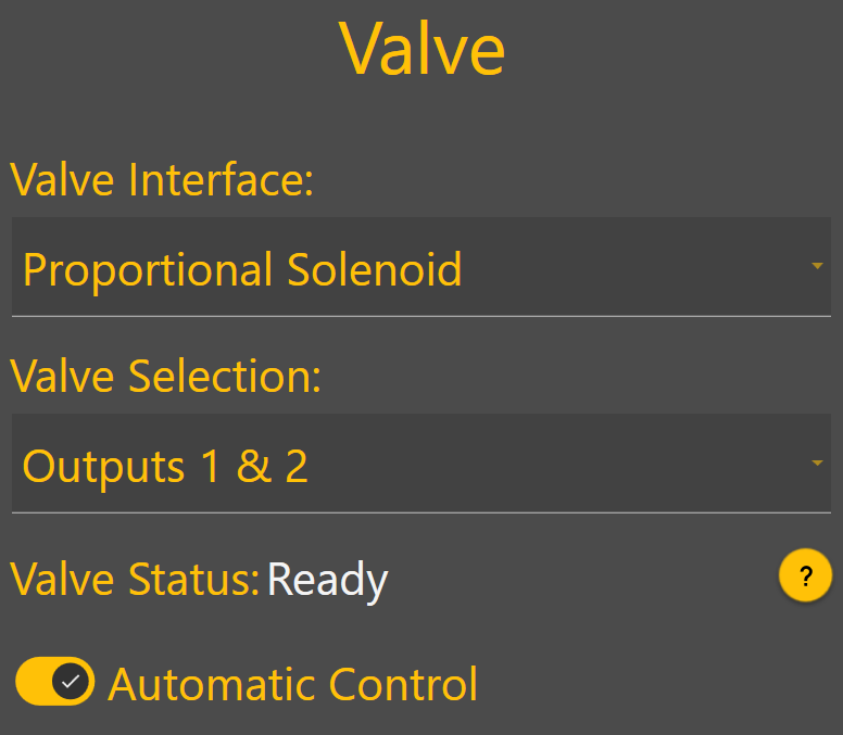](https://docs.t3rra.com/uploads/images/gallery/2026-09/gdHimage.png) In **Level COMMAND**: 1. Select **Proportional Solenoid** as the valve interface. 2. Assign the required valve outputs to each controlled function. 3. Verify that each function moves in the intended direction, then complete valve threshold and cylinder calibration. For detailed configuration and calibration instructions, refer to the **Level COMMAND Manual**.**NOTE:** The external valve block must have the hydraulic supply and return connections required by the implement manufacturer. Configure any tractor remote supplying the valve block according to those instructions.
## Operation Notes**NOTE:** If manual control is not already provided, install a compatible joystick as described in **Section 6.3**.
**COMMAND** must be armed for a connected joystick to operate the valve outputs. Use the **COMMAND Arm/Engage switch** to arm the system and engage automatic control. Joystick movement can disengage automatic control or temporarily override it, depending on the selected joystick configuration. Confirm the configured behaviour during commissioning and demonstrate it to the operator.**IMPORTANT:** To stop automatic control, press the momentary side of the **COMMAND Arm/Engage switch**. Move the switch to **OFF** to disarm **COMMAND** and disable its hydraulic control outputs. Disarming also disables valve operation from a COMMAND-connected joystick.
# 7.7 | Fendt ONE — 900 Gen 6/7 & 1000 Gen 2/3 **Applicable to:** Supported Fendt 900 Gen 6/7 and Fendt 1000 Gen 2/3 tractors using the **COMMAND Fendt ONE** valve interface. ## Connection Method **COMMAND** connects to the tractor’s rear SCV system using the **T3H-V005 ISO Valve Adapter**. The adapter is installed inline between the tractor chassis harness and the SCV-bank harness. It connects the tractor-side and valve-side CAN networks to **COMMAND** through the **CAN Interface** connection on the **T3H-C002** ECU breakout harness. The tractor connection is located at the rear of the machine, on the **right-hand side behind the ISOBUS socket**. ## Installation Steps [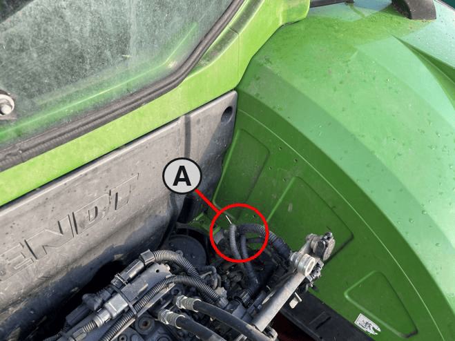](https://docs.t3rra.com/uploads/images/gallery/2026-09/hoaimage.png)1. Complete the machine preparation steps in **Section 5.1** and isolate the tractor electrical supply. 2\. Locate the SCV-bank harness connection behind the rear ISOBUS socket, shown as **A** in the location image. **(A) –** SCV / Chassis Harness connection [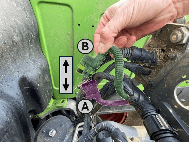](https://docs.t3rra.com/uploads/images/gallery/2026-09/Mb7image.png) 3\. Release the connector latch and disconnect the **SCV-bank harness receptacle (A)** from the **tractor chassis harness plug (B)**. **(A) –** SCV Bank Harness Receptacle **(B) –** Tractor Chassis harness plug [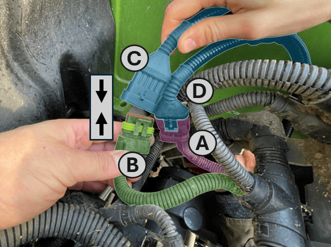](https://docs.t3rra.com/uploads/images/gallery/2026-09/BYqimage.png) 4\. Connect the **tractor-side receptacle (C)** on the **T3H-V005** adapter to the **tractor chassis harness plug (B)**. 5\. Connect the **valve-side plug (D)** on the **T3H-V005** adapter to the **SCV-bank harness receptacle (A)**. **(A)** – SCV Bank Harness Receptacle **(B)** – Tractor Chassis Harness Plug **(C)** – T3H-V005 Harness ‘Tractor’ Receptacle **(D)** – T3H-V005 Harness ‘Valve Block’ Plug [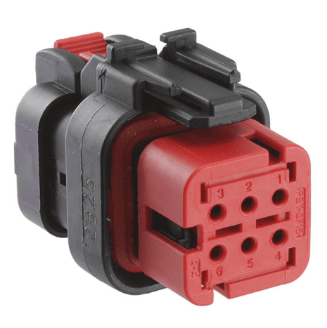](https://docs.t3rra.com/uploads/images/gallery/2026-09/9LAimage.png)6. Route the adapter to the **COMMAND** ECU and connect it to the **Tractor/Valve CAN Interface** connector (pictured right) on the **T3H-C002** ECU breakout harness. 7\. Ensure all connectors are fully seated and latched. Secure the harness clear of moving parts, hot surfaces and sharp edges, leaving sufficient slack to avoid strain on the connectors. 8\. Keep **COMMAND** disarmed and restore the electrical supply.**IMPORTANT:** The SCV-bank harness connection and the nearby ISOBUS socket connection serve different purposes. Connect **T3H-V005** to the SCV-bank harness as shown.
Where an ISOBUS connection is required for the installation, follow **Section 5.4** using the appropriate **COMMAND** cab or exterior breakout harness.
## Tractor Valve Configuration 1. Ensure the required tractor SCVs are enabled and unlocked using the tractor’s controls. 2. In **Level COMMAND**, select **Fendt ONE** as the valve interface. 3. Assign the required SCVs to the controlled functions, such as height and cross-slope. These assignments must match the implement’s hydraulic hose connections. 4. Verify valve communication and confirm that each function operates the intended valve in the correct direction. 5. Complete valve configuration and calibration before automatic operation. For detailed configuration and calibration instructions, refer to the **Level COMMAND Manual**. ## Operation Notes To prepare the selected SCVs for automatic control: 1. Ensure the required tractor SCVs are enabled and unlocked. 2. Move the **COMMAND Arm/Engage switch** to the middle **ON** position to arm COMMAND. 3. Move each selected SCV’s tractor control lever into the **float position** to enable external control of that valve. 4. Press the momentary side of the **COMMAND Arm/Engage switch** to engage automatic control once the system is ready.**NOTE:** For SCVs configured for **COMMAND** control, the lever’s **float position** enables external hydraulic control. It does **not** place the valve into hydraulic float.
Before handing over the installation, verify manual valve operation and demonstrate how to enable, disengage and resume automatic control.**IMPORTANT:** To disengage **COMMAND** automatic control, press the momentary side of the **COMMAND Arm/Engage switch**. Move the switch to **OFF** to disarm **COMMAND** and disable its hydraulic control commands.
# 7.8 | Fendt 800 SCR/S4 **Applicable to:** Supported Fendt 800 SCR/S4 tractors using the **COMMAND Fendt SCR/S4/MT** valve interface. ## Connection Method **COMMAND** connects to the tractor’s rear SCV system using the **T3H-V005 ISO Valve Adapter** and the **S/109 — Fendt 800 SCR/S4 Adapter Harness**, specified for SolSteer kit **K/SCV/008**. The **S/109** harness is installed inline between the tractor chassis harness and the valve harness. It connects to **T3H-V005**, which routes the tractor-side and valve-side CAN networks to the **CAN Interface** connection on the **T3H-C002** ECU breakout harness. The tractor connection consists of a pair of **4-way connectors**, located behind the panel under the **rear-right wheel arch**.**NOTE:** Depending on the tractor specification, an additional valve harness may be connected in series, providing two identical connections in this harness chain. Either of these connections can be used.
## Installation Steps 1\. Complete the machine preparation steps in **Section 5.1** and isolate the tractor electrical supply. [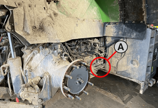](https://docs.t3rra.com/uploads/images/gallery/2026-09/OZdimage.png) 2\. Locate the valve/chassis harness connection behind the panel under the rear-right wheel arch, shown as **A** in the location image. [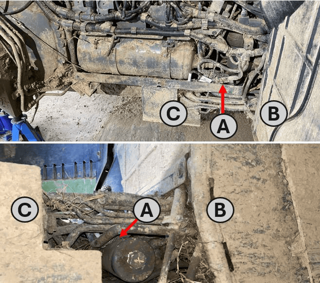](https://docs.t3rra.com/uploads/images/gallery/2026-09/dRZimage.png) 3\. Alternatively, it may be accessed from underneath the machine **(A)** – the bundle can be found amongst the hydraulic lines between the front of the wheel arch **(B)** and the valve block bracket **(C)**. **(A)** - Valve/Tractor Harness bundle **(B)** - Front of the Rear Right Wheel Arch **(C)** - Valve Bracket, behind Rear Right Wheel [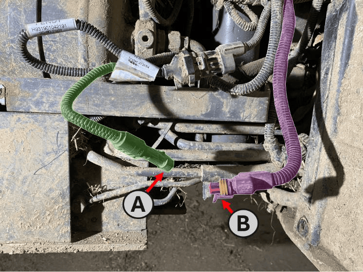](https://docs.t3rra.com/uploads/images/gallery/2026-09/XV4image.png) 3\. Release the connector latch and disconnect the **4-way valve harness receptacle (A)** from the **tractor chassis harness plug (B)**. [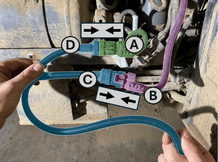](https://docs.t3rra.com/uploads/images/gallery/2026-09/R5oimage.png) 4\. Connect the **4-way “Tractor” receptacle (C)** on the **S/109** harness to the **tractor chassis harness plug (B)**. 5\. Connect the **4-way “Valve” plug (D)** on the **S/109** harness to the **valve harness receptacle (A)**. **(A)** – Receptacle on Machine Valve Harness **(B)** – Plug on Tractor Chassis Harness **(C)** – ‘Tractor’ Receptacle on S/109 Adaptor Harness **(D)** – ‘Valve’ Plug on S/109 Adaptor Harness 6\. Route the **S/109** harness towards the rear of the tractor. 7\. Connect the **5-way receptacle** on the **S/109** harness to the **valve-side plug** on **T3H-V005**. 8\. Connect the **5-way plug** on the **S/109** harness to the **tractor-side receptacle** on **T3H-V005**. 9\. Route **T3H-V005** to the **COMMAND** ECU and connect it to the **CAN Interface** connector on the **T3H-C002** ECU breakout harness. 10\. Ensure all connectors are fully seated and latched. Secure the harness clear of the tyre, moving parts, hot surfaces and sharp edges, leaving sufficient slack to avoid strain on the connectors. 11\. Refit any components removed for access. Keep **COMMAND** disarmed and restore the electrical supply.**IMPORTANT:** The valve-harness connection and the connection at the rear ISOBUS socket serve different purposes. Connect **S/109** to the valve/chassis harness connection identified above.
Where an ISOBUS connection is required for the installation, follow **Section 5.4** using the appropriate **COMMAND** cab or exterior breakout harness.
## Tractor Valve Configuration 1. Ensure the required tractor SCVs are enabled and unlocked using the tractor’s controls. 2. In **Level COMMAND**, select **Fendt SCR/S4/MT** as the valve interface. 3. Assign the required SCVs to the controlled functions, such as height and cross-slope. These assignments must match the implement’s hydraulic hose connections. 4. Prepare the selected SCVs for external control as described below, then verify that each function operates the intended valve in the correct direction. 5. Complete valve configuration and calibration before automatic operation. For detailed configuration and calibration instructions, refer to the **Level COMMAND Manual**. ## Operation Notes To prepare the selected SCVs for automatic control: 1. Ensure the required tractor SCVs are enabled and unlocked. 2. Move the **COMMAND Arm/Engage switch** to the middle **ON** position to arm COMMAND. 3. Move each selected SCV’s tractor control lever into the **float position** to enable external control of that valve. 4. Press the momentary side of the **COMMAND Arm/Engage switch** to engage automatic control once the system is ready.**NOTE:** For SCVs configured for **COMMAND** control, the lever’s **float position** enables external hydraulic control. It does **not** place the valve into hydraulic float.
**IMPORTANT:** To disengage **COMMAND** automatic control, press the momentary side of the **COMMAND Arm/Engage switch**. Move the switch to **OFF** to disarm **COMMAND** and disable its hydraulic control commands.
Before handing over the installation, verify manual valve operation and demonstrate how to enable, disengage and resume automatic control. # 7.9 | Fendt 900 SCR/S4 **Applicable to:** Supported Fendt 900 SCR/S4 tractors using the **COMMAND Fendt SCR/S4/MT** valve interface. ## Connection Method **COMMAND** connects to the tractor’s rear SCV system using the **T3H-V005 ISO Valve Adapter** and the **S/111 — Fendt 900 S4/SCR Adapter Harness**. The **S/111** harness is installed inline between the tractor chassis harness and the valve harness. It connects to **T3H-V005**, which routes the tractor-side and valve-side CAN networks to the **Tractor & Valve CAN Interface** 6-way connection on the **T3H-C002** ECU breakout harness. ## Installation Steps**NOTE:** The connection may be accessed from beneath the tractor, between the front of the rear-right wheel arch and the valve-block bracket. Removing the rear-right wheel and access panel provides additional access where required; follow the tractor manufacturer’s service instructions.
1\. Complete the machine preparation steps in **Section 5.1** and isolate the tractor electrical supply. [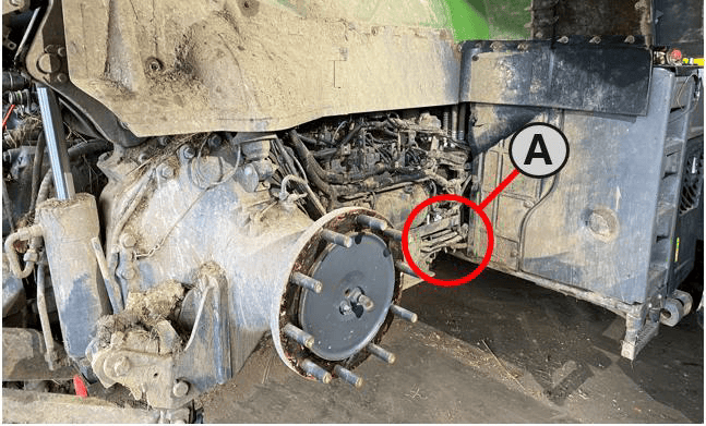](https://docs.t3rra.com/uploads/images/gallery/2026-09/Uzeimage.png)2. Locate the valve/chassis harness connection behind the panel under the rear-right wheel arch, shown as **A** in the location image. **(A)** - Valve/chassis harness connection [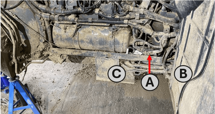](https://docs.t3rra.com/uploads/images/gallery/2026-09/7Avimage.png) 3\. Release the connector latch and disconnect the **valve harness receptacle (A — X1587\_P)** from the **tractor chassis harness plug (B — X1586\_S)**. **(A)** - Valve/Chassis Harness connection **(B)** - Front of the Rear Right Wheel Arch **(C)** - Valve Bracket, Inside Rear Right Wheel [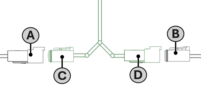](https://docs.t3rra.com/uploads/images/gallery/2026-09/XD1image.png) 4\. Connect the **4-way “VALVES” plug (C)** on the **S/111** harness to the **valve harness receptacle (A)**. **(A)** - Valve harness receptacle (X1587\_P) **(B)** - Chassis harness plug (X1586\_S) **(C)** - ‘VALVES’ Plug S/111 Adaptor Harness **(D)** - ‘TRACTOR’ Receptacle S/111 Adaptor Harness 5\. Connect the **4-way “TRACTOR” receptacle (D)** on the **S/111** harness to the **tractor chassis harness plug (B)**. 6\. Connect the **5-way plug** on the **S/111** harness to the **tractor-side receptacle** on **T3H-V005**. 7\. Connect the **5-way receptacle** on the **S/111** harness to the **valve-side plug** on **T3H-V005**. 8\. Route **T3H-V005** to the **COMMAND** ECU and connect it to the **CAN Interface** connector on the **T3H-C002** ECU breakout harness. 9\. Ensure all connectors are fully seated and latched. Secure the harness clear of the tire, moving parts, hot surfaces and sharp edges, leaving sufficient slack to avoid strain on the connectors. 10\. Refit any components removed for access. Keep **COMMAND** disarmed and restore the electrical supply.**IMPORTANT:** The 4-way valve-harness connection and the 4-way connection at the rear ISOBUS socket serve different purposes. Connect **S/111** to the valve/chassis harness connection identified above.
Where an ISOBUS connection is required for the installation, follow **Section 5.4** using the appropriate **COMMAND** cab or exterior breakout harness.
## Tractor Valve Configuration 1. Ensure the required tractor SCVs are enabled and unlocked using the tractor’s controls. 2. In **Level COMMAND**, select **Fendt SCR/S4/MT** as the valve interface. 3. Assign the required SCVs to the controlled functions, such as height and cross-slope. These assignments must match the implement’s hydraulic hose connections. 4. Prepare the selected SCVs for external control as described below, then verify that each function operates the intended valve in the correct direction. 5. Complete valve configuration and calibration before automatic operation. For detailed configuration and calibration instructions, refer to the **Level COMMAND Manual**. ## Operation Notes To prepare the selected SCVs for automatic control: 1. Ensure the required tractor SCVs are enabled and unlocked. 2. Move the **COMMAND Arm/Engage switch** to the middle **ON** position to arm COMMAND. 3. Move each selected SCV’s tractor control lever into the **float position** to enable external control of that valve. 4. Press the momentary side of the **COMMAND Arm/Engage switch** to engage automatic control once the system is ready.**NOTE:** For SCVs configured for **COMMAND** control, the lever’s **float position** enables external hydraulic control. It does **not** place the valve into hydraulic float.
**IMPORTANT:** To disengage **COMMAND** automatic control, press the momentary side of the **COMMAND Arm/Engage switch**. Move the switch to **OFF** to disarm **COMMAND** and disable its hydraulic control commands.
Before handing over the installation, verify manual valve operation and demonstrate how to enable, disengage and resume automatic control. # 7.10 | Fendt / Challenger MT **Applicable to:** Supported Fendt and Challenger MT tractors using the **COMMAND Fendt SCR/S4/MT** valve interface. ### Connection Method **COMMAND** connects to the tractor’s rear SCV system using the **T3H-V005 ISO Valve Adapter** and the **S/082 — Fendt/Challenger MT Adapter Harness**. The **S/082** harness is installed inline between the tractor chassis harness and the SCV-bank harness. It connects to **T3H-V005**, which routes the tractor-side and valve-side CAN networks to the **Tractor & Valve CAN Interface** connection on the **T3H-C002** ECU breakout harness. The tractor connection is located at the **rear-left of the machine**. The SCV-bank harness receptacle is a **flange-mounted 12-way Deutsch connector**, secured to a bracket behind the SCV bank. ### Installation Steps 1\. Complete the machine preparation steps in **Section 5.1** and isolate the tractor electrical supply. 2\. Connect the **5-way plug** on the **S/082** harness to the **tractor-side receptacle** on **T3H-V005**. 3\. Connect the **5-way receptacle** on the **S/082** harness to the **valve-side plug** on **T3H-V005**. [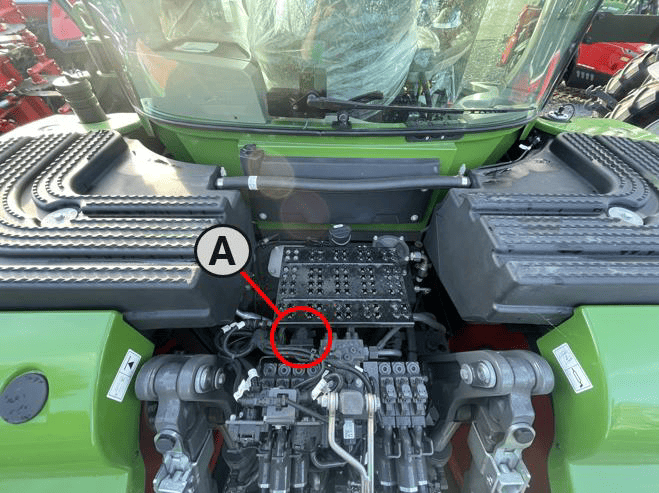](https://docs.t3rra.com/uploads/images/gallery/2026-09/avGimage.png) 4\. Locate the 12-way SCV-bank harness connection at the rear-left of the tractor. **(A)** - SCV Bank Harness connections [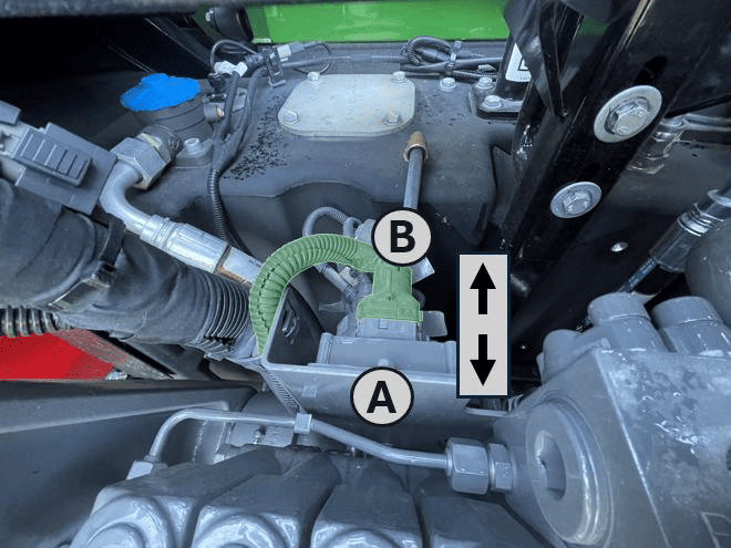](https://docs.t3rra.com/uploads/images/gallery/2026-09/Fqzimage.png) 5\. Release the connector latch and disconnect the **tractor chassis harness plug (B)** from the **SCV-bank harness receptacle (A)**. **(A)** – SCV Bank Harness Receptacle **(B)** – Tractor Chassis Harness Plug 6\. Connect the **tractor chassis harness plug (B)** to the **12-way “Tractor” receptacle (D)** on the **S/082** harness. 7\. Connect the **12-way “Implement PCB” plug (C)** on the **S/082** harness to the **SCV-bank harness receptacle (A)**. **(A)** – SCV Bank Harness Receptacle **(B)** – Tractor Chassis Harness Plug **(C)** – Implement PCB Plug, S/082 Harness Adaptor **(D)** – Tractor Receptacle, S/082 Harness Adaptor [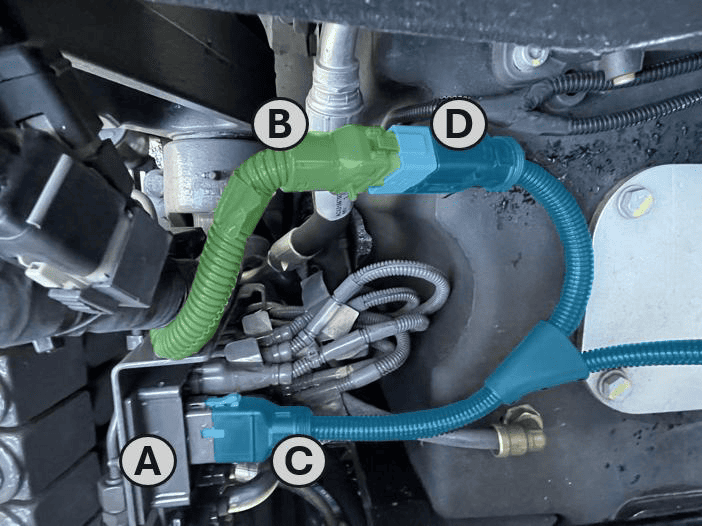](https://docs.t3rra.com/uploads/images/gallery/2026-09/hGMimage.png) 8\. Route **T3H-V005** to the **COMMAND** ECU and connect it to the **CAN Interface** connector on the **T3H-C002** ECU breakout harness. 9\. Ensure all connectors are fully seated and latched. Secure the harness clear of moving parts, hot surfaces and sharp edges, leaving sufficient slack to avoid strain on the connectors. 10\. Keep **COMMAND** disarmed and restore the electrical supply.**IMPORTANT:** The 12-way SCV-bank harness connection and the connection at the rear ISOBUS socket serve different purposes. Connect **S/082** to the SCV-bank harness connection identified above.
Where an ISOBUS connection is required for the installation, follow **Section 5.4** using the appropriate **COMMAND** cab or exterior breakout harness. ### Tractor Valve Configuration 1. Ensure the required tractor SCVs are enabled and unlocked using the tractor’s controls. 2. In **Level COMMAND**, select **Fendt SCR/S4/MT** as the valve interface. 3. Assign the required SCVs to the controlled functions, such as height and cross-slope. These assignments must match the implement’s hydraulic hose connections. 4. Prepare the selected SCVs for external control as described below, then verify that each function operates the intended valve in the correct direction. 5. Complete valve configuration and calibration before automatic operation. For detailed configuration and calibration instructions, refer to the **Level COMMAND Manual**. ### Operation Notes To prepare the selected SCVs for automatic control: 1. Ensure the required tractor SCVs are enabled and unlocked. 2. Move the **COMMAND Arm/Engage switch** to the middle **ON** position to arm COMMAND. 3. Move each selected SCV’s tractor control lever into the **float position** to enable external control of that valve. 4. Press the momentary side of the **COMMAND Arm/Engage switch** to engage automatic control once the system is ready.**NOTE:** For SCVs configured for COMMAND control, the lever’s **float position** enables external hydraulic control. It does **not** place the valve into hydraulic float.
**IMPORTANT:** To disengage **COMMAND** automatic control, press the momentary side of the **COMMAND Arm/Engage switch**. Move the switch to **OFF** to disarm **COMMAND** and disable its hydraulic control commands.
Before handing over the installation, verify manual valve operation and demonstrate how to enable, disengage and resume automatic control.